EP0289640A1 - Seaming machines, especially for seaming dewatering and dry screens, felts and the like - Google Patents
Seaming machines, especially for seaming dewatering and dry screens, felts and the like Download PDFInfo
- Publication number
- EP0289640A1 EP0289640A1 EP87106666A EP87106666A EP0289640A1 EP 0289640 A1 EP0289640 A1 EP 0289640A1 EP 87106666 A EP87106666 A EP 87106666A EP 87106666 A EP87106666 A EP 87106666A EP 0289640 A1 EP0289640 A1 EP 0289640A1
- Authority
- EP
- European Patent Office
- Prior art keywords
- thread
- hooks
- separator according
- needles
- row
- Prior art date
- Legal status (The legal status is an assumption and is not a legal conclusion. Google has not performed a legal analysis and makes no representation as to the accuracy of the status listed.)
- Granted
Links
Images


Classifications
-
- D—TEXTILES; PAPER
- D21—PAPER-MAKING; PRODUCTION OF CELLULOSE
- D21F—PAPER-MAKING MACHINES; METHODS OF PRODUCING PAPER THEREON
- D21F1/00—Wet end of machines for making continuous webs of paper
- D21F1/0027—Screen-cloths
- D21F1/0054—Seams thereof
Definitions
- the invention relates to a thread separator for sewing machines, in particular for sewing drainage fabrics, dryer fabrics, felting and the like.
- a separator head in a to the plane of the row to be separated threads of the screen fabric substantially perpendicular plane which is movable in this plane and can be pushed against the thread row, with a leg behind the thread row of the separator head, which has an inlet gap for the thread row has and with a in the separating head by a controllable drive with respect to the thread row in a guide groove displaceable needle.
- Known thread separators of this type are required for separating threads in the seam formation for closing open woven fabric webs by means of an auxiliary chain, the warp thread ends of the fabric web held on both sides of the auxiliary chain being detected and alternately in from both sides the subject formed in the auxiliary chain are introduced.
- Automation of the entire seam formation process presupposes that this process runs smoothly insofar as the thread separator always separates the warp thread ends only one thread is gripped and severed from the row of threads, and not several, whereby this grasping must also exclude with certainty that the thread to be separated is impaled by the thread separator.
- the known thread separator fulfills these requirements only inadequately, so that the object of the invention is to optimize the functional reliability of the thread separator in that the hook needles are designed in such a way that a separation of the foremost thread in each case of a line of longitudinal thread ends of a fabric is achieved and all Piercing and taking away the following thread is avoided.
- the hook needles are designed as compartment needles, which are provided with hooks, of which at least two with respect to the top and the bottom of the fabric associated with the row of threads are opposite each other in the same plane or parallel planes, the tips of which each opposite thread surface are directed and their concave recesses are shaped to match the diameter and shape of the individual threads to be picked up in such a way that piercing of the thread to be separated by the tips and taking away the following thread can be avoided.
- This construction ensures that with the aid of a hook system consisting of at least two opposing hooks of the compartment needles, each matched to the threads to be separated, depending on the control, coming from the running side or paper side direction, the foremost warp thread of a row of threads is gripped and separated, whereby one of the hooks is responsible for a particular type of thread and / or one side of the fabric.
- the thread separator shown in Fig. 1 is known. It differs from the thread separator according to the invention shown in FIG. 2 essentially only with regard to the single looper needle with only one hook, so that the same reference numerals are used for the corresponding parts of the thread separator of further embodiments.
- the thread separator 1 has a separator head 2, which is arranged in a thread 13 (FIGS. 3 and 4) which is to be separated from one another to the plane of a row 9, that is to say to be separated, in a substantially vertical plane and can be displaced in this plane against the thread row.
- the separating head 2 there is at least one gripper needle which can be displaced by a controllable drive with respect to the thread row and which is movable in a groove 3 in the separating head and acted upon by a leaf spring 16 and which is designed as a section needle 4 provided with at least one hook 6, 7.
- the compartment needle or compartment needles have at least two hooks 6, 7 opposite each other in the same plane with respect to the top 5 and bottom 8 of the fabric strip or magazine bundle belonging to the thread row 9, the tips 10, 11 of which are directed towards the respective opposite thread surface 12.
- the hooks 6, 7 are each provided with a concave recess 14, 15, which - as can be seen from FIGS. 2, 3 and 4 - advantageously lie in a compartment needle.
- These concave recesses have a radius of curvature which corresponds to the curvature of the surface 12 of the thread 13, and can therefore also be curved differently to adapt to the diameter of the thread 13 to be picked up during separation.
- the length of the arc of curvature of the concave recesses 14, 15 of the hooks 6, 7 corresponds to approximately half the thread circumference in the case of a circular thread cross section, as shown in FIGS. 3 and 4.
- the shape of the hooks 6, 7 is selected so that piercing of the thread 13 to be separated by the respective tip 10, 11 and entrainment of the follower thread 18 are avoided.
- the mutual spacing of the tips 10, 11 of the hooks 6, 7 is selected as shown in FIG. 2 that it corresponds approximately to the width (a) of the inlet gap 17 in the separating head 2 for the thread row 9.
- This inlet gap width is adapted to the fabric thickness and is approximately between 0.5 and 3 mm, a width of 1.0 mm having proven to be particularly advantageous.
- a narrow guide groove in the separator head without rounded edges is advantageous for optimal functioning of the thread separator, so that with appropriate adjustment of the configuration of the hooks or compartment needles, the guide groove and the inlet gap width, a tension adjustment of the fabric strip is unnecessary, by which to ensure the desired functional reliability of the thread separator, ie to avoid piercing and taking along the subsequent thread 18 when separating the thread 13 with certainty.
- a tension adjustment of the fabric strip is unnecessary, by which to ensure the desired functional reliability of the thread separator, ie to avoid piercing and taking along the subsequent thread 18 when separating the thread 13 with certainty.
- a e.g. compartment needle with a double hook inside the thread separator prevents weaving errors in the seam by simultaneously twisting two threads.
- FIGS. 5 to 7 schematically show, using a partial side view of a compartment needle 4 according to the invention with its double hook, the manner in which the needle separates the threads in different types of fabric.
- the two hooks of the needle marked in FIGS. 2 to 4 with 6 and 7 but not shown in FIGS. 5 to 7 are adapted in size to the respective warp thread diameters and take this depending on Control from the leading side and paper side direction of the front warp thread to separate it.
- the compartment needles 4 are controlled via a programmed cam disc in the program switching mechanism or, in the case of jacquard seams, via program needles and the correspondingly programmed jacquard card.
- the digits 1 to 7 (Fig. 5), 1 to 10 (Fig. 6) and 1 to 9 (Fig. 7) and their page assignment show the order and the page affiliation of the taps made by the hooks.
- the left or lower hook of the section needle 4 is required to separate the warp threads 2, 3, 5 and 7 on the paper side of the fabric, while the right, upper hook of the section needle the warp threads 1 , 4 and 6 isolated on the running side of the fabric.
- the so-called F-23 fabric the second and third warp threads on the paper side are consecutive and all others are alternately picked up or tapped alternately between the running side and the paper side.
- the mode of operation of the thread separator according to the invention or the compartment needle 4 with double hook used in separating threads of a composite fabric is shown in FIG. 6.
- the paper side and the running side of the fabric are picked up alternately by the lower and upper hook.
- FIG. 6 For another composite fabric, as can be seen from FIG.
- the warp threads are separated in alternation between paper side, paper side and running side of the fabric, working with a small hook for the paper side and a large hook for the running side, as from the different diameters the threads of the paper side and the running side shown in section and also from the different hook sizes of the double hook of this compartment needle can be seen.
- the construction according to the invention also has the advantage that the dividing needle 4 fits into any standard thread separator or that each such thread separator can be retrofitted with little effort in this regard.
- the functional improvement not only means that the simultaneous separation of two successive threads is avoided, but also that the setting of the thread separator is simplified.
- the separator head For many fabrics, it is sufficient to work with a single section needle in the separator head, the opposite hooks of which are shaped depending on the fabric. In the case of fabrics with several types of longitudinal thread of different thicknesses, however, it may be necessary to arrange a plurality of section needles one above the other in the guide groove of the separating head, each needle being individually movable and, according to a control program, dividing the threads of the thread types assigned to them. As shown in FIG. 8, the compartment needles can also be provided with only one hook, it being noted that at least two of all the hooks are arranged opposite one another.
- the invention is not limited to certain, e.g. circular hook shapes limited.
- the recesses can also be profiled threads such as Be adapted to flat wires.
Abstract
Description
Die Erfindung betrifft einen Fadentrenner für Nahtmaschinen, insbesondere zum Nahten von Entwässerungssieben, Trockensieben, Filzen u. dgl., mit einem Trennerkopf in einer zur Ebene der Reihe voneinander zu trennender Fäden des Siebgewebes im wesentlichen senkrechten Ebene, die in dieser Ebene bewegbar und gegen die Fadenreihe vorschiebbar ist, mit einem die Fadenreihe hintergreifenden Schenkel des Trennerkopfes, der einen Einlaufspalt für die Fadenreihe aufweist und mit einer im Trennerkopf durch einen steuerbaren Antrieb in bezug auf die Fadenreihe in einer Führungsnut verlagerbaren Greifernadel.The invention relates to a thread separator for sewing machines, in particular for sewing drainage fabrics, dryer fabrics, felting and the like. Like., With a separator head in a to the plane of the row to be separated threads of the screen fabric substantially perpendicular plane which is movable in this plane and can be pushed against the thread row, with a leg behind the thread row of the separator head, which has an inlet gap for the thread row has and with a in the separating head by a controllable drive with respect to the thread row in a guide groove displaceable needle.
Derartige bekannte Fadentrenner (DE-GM 81 22 450) werden zum Vereinzeln von Fäden bei der Nahtbildung zum Schliessen offen gewebter Gewebebahnen mittels Hilfskette benötigt, wobei die zu beiden Seiten der Hilfskette in einem Magazinierbund gehaltenen Kettfadenenden der Gewebebahn erfaßt und abwechselnd von beiden Seiten her in das in der Hilfskette gebildete Fach eingeführt werden. Eine Automatisierung des gesamten Nahtbildungsvorgangs setzt voraus, daß dieser Vorgang reibungslos abläuft insofern, als der Fadentrenner für das Vereinzeln der Kettfadenenden immer nur einen Faden erfaßt und von der Fadenreihe abrennt, und nicht mehrere, wobei dieses Erfassen auch mit Sicherheit ausschließen muß, daß der abzutrennende Faden vom Fadentrenner aufgespießt wird.Known thread separators of this type (DE-GM 81 22 450) are required for separating threads in the seam formation for closing open woven fabric webs by means of an auxiliary chain, the warp thread ends of the fabric web held on both sides of the auxiliary chain being detected and alternately in from both sides the subject formed in the auxiliary chain are introduced. Automation of the entire seam formation process presupposes that this process runs smoothly insofar as the thread separator always separates the warp thread ends only one thread is gripped and severed from the row of threads, and not several, whereby this grasping must also exclude with certainty that the thread to be separated is impaled by the thread separator.
Der bekannte Fadentrenner erfüllt diese Forderungen nur unzulänglich, so daß die Aufgabe der Erfindung darin besteht, die Funktionssicherheit des Fadentrenners dadurch zu optimieren, daß die Greifernadeln so ausgebildet sind, daß mit Sicherheit ein Vereinzeln des jeweils vordersten Fadens einer Längsfadenendenaufreihung eines Gewebes erreicht wird und jegliches Anstechen und Mitnehmen des Folgefadens vermieden wird.The known thread separator fulfills these requirements only inadequately, so that the object of the invention is to optimize the functional reliability of the thread separator in that the hook needles are designed in such a way that a separation of the foremost thread in each case of a line of longitudinal thread ends of a fabric is achieved and all Piercing and taking away the following thread is avoided.
Diese Aufgabe wird erfindungsgemäß dadurch gelöst, daß die Greifernadeln als Abteilnadeln ausgebildet sind, die mit Haken versehen sind, von denen mindestens zwei in bezug auf die Oberseite und die Unterseite des der Fadenreihe zugehörigen Gewebes einander in derselben Ebene oder parallelen Ebenen gegenüberliegen, deren Spitzen zur jeweils gegenüberliegenden Fadenoberfläche gerichtet sind und deren konkave Ausnehmungen in Anpassung an Durchmesser und Form der beim Abtrennen aufzunehmenden einzelnen Fäden so geformt sind, daß ein Anstechen des abzutrennenden Fadens durch die Spitzen und ein Mitnehmen des Folgefadens vermeidbar sind.This object is achieved in that the hook needles are designed as compartment needles, which are provided with hooks, of which at least two with respect to the top and the bottom of the fabric associated with the row of threads are opposite each other in the same plane or parallel planes, the tips of which each opposite thread surface are directed and their concave recesses are shaped to match the diameter and shape of the individual threads to be picked up in such a way that piercing of the thread to be separated by the tips and taking away the following thread can be avoided.
Durch diese Konstruktion wird erreicht, daß mit Hilfe eines Hakensystems, bestehend aus mindestens zwei einander gegenüberliegenden, jeweils auf die abzutrennenden Fäden abgestimmten Haken der Abteilnadeln je nach Steuerung von der Laufseiten- oder Papierseitenrichtung kommend, der vorderste Kettfaden einer Fadenreihe ergriffen und vereinzelt wird, wobei jeweils einer der Haken für jeweils eine bestimmte Fadensorte und/oder eine Seite des Gewebes zuständig ist.This construction ensures that with the aid of a hook system consisting of at least two opposing hooks of the compartment needles, each matched to the threads to be separated, depending on the control, coming from the running side or paper side direction, the foremost warp thread of a row of threads is gripped and separated, whereby one of the hooks is responsible for a particular type of thread and / or one side of the fabric.
Durch vorteilhafte Ausgestaltungen des Erfindungsvor schlags, die in den Unteransprüchen 2 bis 8 gekennzeichnet sind, lassen sich die Hakenkonturen und Kombinationen im Hinblick auf die Funktion der Abteilnadeln optimieren.By advantageous embodiments of the invention impact, which are characterized in
Weitere vorteilhafte Ausgestaltungen nach den Unteransprüchen 9 bis 13 betreffen vorteilhafte Ausbildungen der Abteilnadeln und der Einlaufspaltbreite für verschiedene Gewebearten sowie die Steuerung dieser Abteilnadeln.Further advantageous configurations according to
Die Erfindung wird nachfolgend anhand der in der Zeichnung dargestellten Ausführungsbeispiele näher erläutert. In der Zeichnung zeigen:
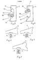
- Fig. 1 eine Längsschnittansicht eines Fadentrenners mit herkömmlicher Greifernadel,
- Fig. 2 eine der Fig. 1 vergleichbare, jedoch schematisierte Längsschnittansicht eines Fadentrenners mit erfindungsgemäßer Abteilnadel,
- Fig. 3 eine schematisierte Schnittansicht des Doppelhakens einer erfindungsgemäßen Abteilnadel mit vereinzeltem Faden im unteren Haken,
- Fig. 4 eine der Fig. 3 vergleichbare, schematische Ansicht des erfindungsgemäßen Doppelhakens mit vereinzeltem Faden im oberen Haken, und
- Fig. 5 bis 8 schematisierte Teilseitenansichten bzw. Schrägansichten der erfindungsgemäßen Abteilnadeln mit unterschiedlichen Hakenkombinationen für unterschiedliche Gewebeformen, nämlich in der Ausführungsform von Fig. 5 für ein Duoform-Gewebe, in den Ausführungsformen von Fig. 6 bis Fig. 8 für Gewebe mit mehreren verschiedenen Längsfadensystemen, wobei in Fig. 8 die Nadeln eines Greifernadelsystems der besseren Verständlichkeit wegen auseinandergerückt gezeichnet sind.
- 1 is a longitudinal sectional view of a thread separator with a conventional looper needle,
- 2 shows a longitudinal sectional view, comparable to FIG. 1, of a thread separator with a section needle according to the invention,
- 3 is a schematic sectional view of the double hook of a compartment needle according to the invention with a single thread in the lower hook,
- Fig. 4 is a schematic view comparable to FIG. 3 of the double hook according to the invention with isolated thread in the upper hook, and
- 5 to 8 schematic partial side views or oblique views of the compartment needles according to the invention with different hook combinations for different fabric shapes, namely in the embodiment of FIG. 5 for a duo-form fabric, in the embodiments of FIGS. 6 to 8 for fabrics with several different ones Longitudinal thread systems, in Fig. 8 the needles of a hook needle system are drawn apart for clarity.
Der in Fig. 1 dargestellte Fadentrenner ist bekannt. Er unterscheidet sich von dem in Fig. 2 dargestellten erfindungsgemäßen Fadentrenner im wesentlichen nur hinsichtlich der einzigen Greifernadel mit nur einem Haken, so daß für die entsprechenden Teile des Fadentrenners weiterer Ausführungsformen die gleichen Bezugszeichen verwendet werden. Der Fadentrenner 1 weist einen Trennerkopf 2 auf, welcher in einer zur Ebene einer Reihe 9 voneinander zu trennender, also zu vereinzelnder Fäden 13 (Fig. 3 und 4) im wesentlichen senkrechten Ebene angeordnet ist und in dieser Ebene gegen die Fadenreihe verschiebbar ist.The thread separator shown in Fig. 1 is known. It differs from the thread separator according to the invention shown in FIG. 2 essentially only with regard to the single looper needle with only one hook, so that the same reference numerals are used for the corresponding parts of the thread separator of further embodiments. The
Im Trennerkopf 2 befindet sich mindestens eine durch einen steuerbaren Antrieb in bezug auf die Fadenreihe verlagerbare, in einer Nut 3 des Trennerkopfes bewegbare, von einer Blattfeder 16 beaufschlagte Greifernadel, die als mit mindestens einem Haken 6, 7 versehene Abteilnadel 4 ausgebildet ist. Die Abteilnadel oder Abteilnadeln weisen mindestens zwei in bezug auf die Oberseite 5 und Unterseite 8 des der Fadenreihe 9 zugehörigen Gewebestreifens bzw. Magazinierbundes einander in derselben Ebene gegenüberliegende Haken 6, 7 auf, deren Spitzen 10, 11 zur jeweils gegenüberliegenden Fadenoberfläche 12 gerichtet sind. Die Haken 6, 7 sind mit je einer konkaven Ausnehmung 14, 15 versehen, die - wie aus den Figuren 2, 3 und 4 entnommen werden kann - in vorteilhaften Ausführungen in einer Abteilnadel liegen. Diese konkaven Ausnehmungen weisen einen Krümmungsradius auf, der der Krümmung der Oberfläche 12 des Fadens 13 entspricht, können also in Anpassung an den Durchmesser des beim Abtrennen aufzunehmenden Fadens 13 auch verschieden gekrümmt sein.In the separating
Die Länge des Krümmungsbogens der konkaven Ausnehmungen 14, 15 der Haken 6, 7 entspricht bei kreisrundem Fadenquerschnitt, wie er in den Fig. 3 und 4 dargestellt ist, in etwa der Hälfte des Fadenumfangs. In jedem Fall ist die Formgebung der Haken 6, 7 so gewählt, daß ein Anstechen des abzutrennenden Fadens 13 durch die jeweilige Spitze 10, 11 und ein Mitnehmen des Folgefadens 18 vermieden werden.The length of the arc of curvature of the
Zu diesem Zweck ist der gegenseitige Abstand der Spitzen 10, 11 der Haken 6, 7 so gewählt, wie aus Fig. 2 ersichtlich, daß er etwa der Breite (a) des im Trennerkopf 2 vorhandenen Einlaufspaltes 17 für die Fadenreihe 9 entspricht. Diese Einlaufspaltbreite ist an die Gewebedicke angepaßt und liegt etwa zwischen 0,5 und 3 mm, wobei sich eine Breite von 1,0 mm als besonders vorteilhaft erwiesen hat. Neben der Einlaufspaltbreite ist für eine optimale Funktionsweise des Fadentrenners eine enge Führungsnut im Trennerkopf ohne gerundete Kanten vorteilhaft, so daß sich bei entsprechender Abstimmung der Kon-figuration der Haken bzw. Abteilnadeln, der Führungsnut und der Einlaufspaltbreite sogar eine Spanndurckeinstellung des Gewebestreifens erübrigt, um die gewünschte Funktionssicherheit des Fadentrenners sicherzustellen, d.h., ein Anstechen und Mitnehmen des Folgefadens 18 beim Vereinzeln des Fadens 13 mit Sicherheit zu vermeiden. Somit können durch die erfindungsgemäße Verwendung einer z.B. mit einem Doppelhaken versehenen Abteilnadel innerhalb des Fadentrenners Webfehler in der Naht durch gleichzeitiges Einschlagen zweier Fäden vermieden werden.For this purpose, the mutual spacing of the
In den Figuren 5 bis 7 ist schematisch anhand einer Teilseitenansicht einer erfindungsgemäßen Abteilnadel 4 mit ihrem Doppelhaken dargestellt, in welcher Weise die Nadel das Vereinzeln der Fäden bei verschiedenen Gewebearten durchführt.FIGS. 5 to 7 schematically show, using a partial side view of a
Bei der Verwendung der Abteilnadel für Duoform-Gewebe sind die beiden in den Fig. 2 bis 4 mit 6 und 7 gekennzeichneten, jedoch in den Fig. 5 bis 7 nicht näher bezeichneten Haken der Nadel größenmäßig an die jeweiligen Kettfadendurchmesser angepaßt und ergreifen den je nach Steuerung von der Laufseiten- und Papierseitenrichtung herkommend vordersten Kettfaden, um ihn zu vereinzeln. Die Steuerung der Abteilnadeln 4 erfolgt dabei über eine programmierte Kurvenscheibe im Programmschaltwerk bzw. beim Jacquard-Nahten über Programm-Nadeln und die entsprechend programmierte Jacquard-Karte. Die Ziffern 1 bis 7 (Fig. 5), 1 bis 10 (Fig. 6) und 1 bis 9 (Fig. 7) und deren Seitenzuordnung zeigen die Reihenfolge und die Seitenzugehörigkeit der durch die Haken erfolgenden Abgriffe. So wird bei dem Duoform-Gewebe gemäß Fig. 5 der linke oder untere Haken der Abteilnadel 4 dazu benötigt, die Kettfäden 2, 3, 5 und 7 auf der Papierseite des Gewebes zu vereinzeln, während der rechte, obere Haken der Abteilnadel die Kettfäden 1, 4 und 6 auf der Laufseite des Gewebes vereinzelt. Dabei ist zu erkennen, daß bei diesem Gewebe, dem sogenannten F-23-Gewebe, der zweite und dritte Kettfaden auf der Papierseite aufeinanderfolgend und alle übrigen im Wechsel zwischen Laufseite und Papierseite vereinzelt bzw. abgegriffen werden. Die Funktionsweise des erfindungsgemäßen Fadentrenners bzw. der in ihm verwendeten Abteilnadel 4 mit Doppelhaken beim Vereinzeln von Fäden eines Verbundgewebes ist in Fig. 6 dargestellt. Hierbei wird im Wechsel die Papierseite und die Laufseite des Gewebes von dem unteren bzw. oberen Haken abgegriffen. Für ein anderes Verbundgewebe geschieht, wie aus Fig. 7 ersichtlich, die Vereinzelung der Kettfäden im Wechsel Papierseite, Papierseite und Laufseite des Gewebes, wobei mit einem kleinen Haken für die Papierseite und einem großen Haken für die Laufseite gearbeitet wird, wie aus den unterschiedlichen Durchmessern der im Schnitt dargestellten Fäden der Papierseite und Laufseite und auch aus den unterschiedlichen Hakengrößen des Doppelhakens dieser Abteilnadel ersichtlich ist.When using the compartment needle for duo-form fabrics, the two hooks of the needle marked in FIGS. 2 to 4 with 6 and 7 but not shown in FIGS. 5 to 7 are adapted in size to the respective warp thread diameters and take this depending on Control from the leading side and paper side direction of the front warp thread to separate it. The
Die erfindungsgemäße Konstruktion hat darüberhinaus den Vorteil, daß die Abteilnadel 4 in jeden Standard-Fadentrenner paßt bzw. jeder derartige Fadentrenner mit einem nur geringen Aufwand diesbezüglich nachgerüstet werden kann. Darüberhinaus führt die Funktionsverbesserung nicht nur dazu, daß das gleichzeitige Vereinzeln zweier aufeinanderfolgender Fäden vermieden wird, sondern auch, daß die Einstellung des Fadentrenners vereinfacht wird.The construction according to the invention also has the advantage that the dividing
Es ist bei vielen Geweben ausreichend, mit einer einzigen Abteilnadel im Trennerkopf zu arbeiten, deren gegenüberliegende Haken abhängig vom Gewebe geformt sind. Bei Geweben mit mehreren unterschiedlich dicken Längsfaden-Sorten kann es jedoch notwendig sein, mehrere Abteilnadeln übereinander in der Führungsnut des Trennerkopfes anzuordnen, wobei jede Nadel einzeln bewegbar ist und einem Steuerungs-Programm folgend jeweils die Fäden der ihr zugeordneten Fadensorte abteilt. Wie Fig. 8 zeigt, können die Abteilnadeln auch mit nur einem Haken versehen sein, wobei zu beachten ist, daß von allen Haken wenigstens zwei gegenüberliegend angeordnet sind.For many fabrics, it is sufficient to work with a single section needle in the separator head, the opposite hooks of which are shaped depending on the fabric. In the case of fabrics with several types of longitudinal thread of different thicknesses, however, it may be necessary to arrange a plurality of section needles one above the other in the guide groove of the separating head, each needle being individually movable and, according to a control program, dividing the threads of the thread types assigned to them. As shown in FIG. 8, the compartment needles can also be provided with only one hook, it being noted that at least two of all the hooks are arranged opposite one another.
Es wird noch darauf hingewiesen, daß sich die Erfindung nicht auf bestimmte, z.B. kreisförmige Hakenformen beschränkt. Selbstverständlich können die Ausnehmungen auch Profilfäden wie z.B. Flachdrähten angepaßt sein.It should be noted that the invention is not limited to certain, e.g. circular hook shapes limited. Of course, the recesses can also be profiled threads such as Be adapted to flat wires.
Claims (13)
Priority Applications (4)
| Application Number | Priority Date | Filing Date | Title |
|---|---|---|---|
| ES198787106666T ES2025577T3 (en) | 1987-05-07 | 1987-05-07 | WIRE SEPARATOR FOR SEWING MACHINES, ESPECIALLY FOR SEWING DRAIN SCREENS, DRYING SCREENS, FELTS AND LIKE. |
| AT87106666T ATE68024T1 (en) | 1987-05-07 | 1987-05-07 | THREAD BREAKER FOR SEWING MACHINES, ESPECIALLY FOR SEWING DEWATERING FABRICS, DRYING FABRICS, FELTING ETC. |
| DE8787106666T DE3773487D1 (en) | 1987-05-07 | 1987-05-07 | THREAD SEPARATOR FOR SEAMING MACHINES, ESPECIALLY FOR SEAMING DRAINAGE SCREENS, DRY SCREENS, FELTS AND THE LIKE |
| EP87106666A EP0289640B1 (en) | 1987-05-07 | 1987-05-07 | Seaming machines, especially for seaming dewatering and dry screens, felts and the like |
Applications Claiming Priority (1)
| Application Number | Priority Date | Filing Date | Title |
|---|---|---|---|
| EP87106666A EP0289640B1 (en) | 1987-05-07 | 1987-05-07 | Seaming machines, especially for seaming dewatering and dry screens, felts and the like |
Publications (2)
| Publication Number | Publication Date |
|---|---|
| EP0289640A1 true EP0289640A1 (en) | 1988-11-09 |
| EP0289640B1 EP0289640B1 (en) | 1991-10-02 |
Family
ID=8196964
Family Applications (1)
| Application Number | Title | Priority Date | Filing Date |
|---|---|---|---|
| EP87106666A Expired - Lifetime EP0289640B1 (en) | 1987-05-07 | 1987-05-07 | Seaming machines, especially for seaming dewatering and dry screens, felts and the like |
Country Status (4)
| Country | Link |
|---|---|
| EP (1) | EP0289640B1 (en) |
| AT (1) | ATE68024T1 (en) |
| DE (1) | DE3773487D1 (en) |
| ES (1) | ES2025577T3 (en) |
Cited By (3)
| Publication number | Priority date | Publication date | Assignee | Title |
|---|---|---|---|---|
| EP0388880A1 (en) * | 1989-03-20 | 1990-09-26 | NOVATECH GmbH Siebe und Technologie für Papier | Separator for seaming machines |
| EP0444587A1 (en) * | 1990-02-26 | 1991-09-04 | NOVATECH GmbH Siebe und Technologie für Papier | Hook and separator containing such hook to pick up and isolate threads |
| WO2005090663A1 (en) * | 2004-03-19 | 2005-09-29 | Wangner Gmbh & Co. Kg | Plate for the separator of a seam weaving machine |
Citations (2)
| Publication number | Priority date | Publication date | Assignee | Title |
|---|---|---|---|---|
| EP0043441A1 (en) * | 1980-07-09 | 1982-01-13 | Hermann Wangner GmbH & Co. KG | Process and apparatus for making a woven seam between two ends of a fabric |
| US4581794A (en) * | 1984-03-07 | 1986-04-15 | Asten Group Inc. | Automatic seaming machine for fabric belts |
Family Cites Families (1)
| Publication number | Priority date | Publication date | Assignee | Title |
|---|---|---|---|---|
| DE8122450U1 (en) * | 1981-07-30 | 1983-01-13 | Fa. F. Oberdorfer, 7920 Heidenheim | DEVICE FOR CONTINUOUSLY DIVIDING THREADS MAINTAINED |
-
1987
- 1987-05-07 ES ES198787106666T patent/ES2025577T3/en not_active Expired - Lifetime
- 1987-05-07 AT AT87106666T patent/ATE68024T1/en not_active IP Right Cessation
- 1987-05-07 EP EP87106666A patent/EP0289640B1/en not_active Expired - Lifetime
- 1987-05-07 DE DE8787106666T patent/DE3773487D1/en not_active Expired - Fee Related
Patent Citations (3)
| Publication number | Priority date | Publication date | Assignee | Title |
|---|---|---|---|---|
| EP0043441A1 (en) * | 1980-07-09 | 1982-01-13 | Hermann Wangner GmbH & Co. KG | Process and apparatus for making a woven seam between two ends of a fabric |
| US4581794A (en) * | 1984-03-07 | 1986-04-15 | Asten Group Inc. | Automatic seaming machine for fabric belts |
| US4581794B1 (en) * | 1984-03-07 | 1989-01-03 |
Cited By (3)
| Publication number | Priority date | Publication date | Assignee | Title |
|---|---|---|---|---|
| EP0388880A1 (en) * | 1989-03-20 | 1990-09-26 | NOVATECH GmbH Siebe und Technologie für Papier | Separator for seaming machines |
| EP0444587A1 (en) * | 1990-02-26 | 1991-09-04 | NOVATECH GmbH Siebe und Technologie für Papier | Hook and separator containing such hook to pick up and isolate threads |
| WO2005090663A1 (en) * | 2004-03-19 | 2005-09-29 | Wangner Gmbh & Co. Kg | Plate for the separator of a seam weaving machine |
Also Published As
| Publication number | Publication date |
|---|---|
| ATE68024T1 (en) | 1991-10-15 |
| ES2025577T3 (en) | 1992-04-01 |
| DE3773487D1 (en) | 1991-11-07 |
| EP0289640B1 (en) | 1991-10-02 |
Similar Documents
| Publication | Publication Date | Title |
|---|---|---|
| EP3347513B1 (en) | Module and weaving machine with a device and method for holding, feeding and introducing weft threads into a shed | |
| DE102012200835B3 (en) | Weaving machine with a device for forming additional shot effects | |
| EP0644286B1 (en) | Arrangement to feed weft yarns | |
| CH653065A5 (en) | DEVICE FOR SEPARATING FLASHLIGHTS OR LAMPS. | |
| EP0990724B1 (en) | Thread-clamping and -severing device for knitting machines | |
| DE3714517A1 (en) | THREAD SEPARATOR FOR SEAMING MACHINES, IN PARTICULAR FOR SEAMING DRAINAGE SCREENS, DRY SCREENS, FELTS AND THE LIKE | |
| EP0289640B1 (en) | Seaming machines, especially for seaming dewatering and dry screens, felts and the like | |
| EP0310767A1 (en) | Gripper needle loom | |
| EP0301174B1 (en) | Separating device for segregating filaments kept in side-by-side arrangement | |
| CH671590A5 (en) | ||
| DE3015191C2 (en) | Thread changing device for textile machines, in particular circular knitting and circular knitting machines | |
| EP0309700B1 (en) | Gripper loom | |
| DE3712169A1 (en) | Thread separator for seaming machines, especially for the seaming of drainage screens, drying screens, felts and the like | |
| EP2021538B1 (en) | Apparatus for forming a selvedge on a gripper weaving machine | |
| EP0444587B1 (en) | Hook and separator containing such hook to pick up and isolate threads | |
| EP0388880B1 (en) | Separator for seaming machines | |
| EP0822998A1 (en) | Power weaving loom | |
| WO2011143787A1 (en) | Tensioning device and method for re-tensioning warp threads of a warp thread layer | |
| DE2418989A1 (en) | DEVICE FOR SELECTING AND FEEDING WEFT FEEDS IN A RULESS LOOM | |
| EP3899121A1 (en) | Giver rapier head, loom with a giver rapier head of this kind and method for double weft insertion | |
| EP1607501A1 (en) | Method and device for shedding jacquard patterned pile warp yarns in a face to face weaving machine | |
| DE2312709B2 (en) | DEVICE FOR WEB MACHINES WITH FIXED STORAGE REELS FOR HOLDING THE END OF A WEFT ENTRY INTO THE WEB COMPARTMENT | |
| CH654602A5 (en) | DEVICE FOR INPUTING CHAIN THREADS IN PROVIDED WEAVING LAMPS AND SLATS. | |
| CH668441A5 (en) | DEVICE ON CONTINUOUS WEAVING MACHINES WITH SHOT ENTRY BY GRIPPERS PROVIDED WITH CLAMPING DEVICES. | |
| DE2758744C2 (en) | Knot hook to form a Gördesknot |
Legal Events
| Date | Code | Title | Description |
|---|---|---|---|
| PUAI | Public reference made under article 153(3) epc to a published international application that has entered the european phase |
Free format text: ORIGINAL CODE: 0009012 |
|
| AK | Designated contracting states |
Kind code of ref document: A1 Designated state(s): AT BE CH DE ES FR GB IT LI NL SE |
|
| 17P | Request for examination filed |
Effective date: 19890406 |
|
| 17Q | First examination report despatched |
Effective date: 19900921 |
|
| GRAA | (expected) grant |
Free format text: ORIGINAL CODE: 0009210 |
|
| AK | Designated contracting states |
Kind code of ref document: B1 Designated state(s): AT BE CH DE ES FR GB IT LI NL SE |
|
| REF | Corresponds to: |
Ref document number: 68024 Country of ref document: AT Date of ref document: 19911015 Kind code of ref document: T |
|
| ITF | It: translation for a ep patent filed |
Owner name: BARZANO' E ZANARDO MILANO S.P.A. |
|
| REF | Corresponds to: |
Ref document number: 3773487 Country of ref document: DE Date of ref document: 19911107 |
|
| GBT | Gb: translation of ep patent filed (gb section 77(6)(a)/1977) | ||
| ET | Fr: translation filed | ||
| PLBE | No opposition filed within time limit |
Free format text: ORIGINAL CODE: 0009261 |
|
| STAA | Information on the status of an ep patent application or granted ep patent |
Free format text: STATUS: NO OPPOSITION FILED WITHIN TIME LIMIT |
|
| 26N | No opposition filed | ||
| PGFP | Annual fee paid to national office [announced via postgrant information from national office to epo] |
Ref country code: CH Payment date: 19940510 Year of fee payment: 8 |
|
| EAL | Se: european patent in force in sweden |
Ref document number: 87106666.8 |
|
| REG | Reference to a national code |
Ref country code: GB Ref legal event code: 732E |
|
| PG25 | Lapsed in a contracting state [announced via postgrant information from national office to epo] |
Ref country code: LI Effective date: 19950531 Ref country code: CH Effective date: 19950531 |
|
| REG | Reference to a national code |
Ref country code: FR Ref legal event code: TP |
|
| REG | Reference to a national code |
Ref country code: ES Ref legal event code: PC2A Owner name: WIS ENGINEERING GMBH. |
|
| NLS | Nl: assignments of ep-patents |
Owner name: WIS ENGINEERING GMBH TE TIMELKAM, OOSTENRIJK. |
|
| ITPR | It: changes in ownership of a european patent |
Owner name: CESSIONE;WIS ENGINEERING GMBH |
|
| REG | Reference to a national code |
Ref country code: CH Ref legal event code: PL |
|
| PGFP | Annual fee paid to national office [announced via postgrant information from national office to epo] |
Ref country code: NL Payment date: 19980531 Year of fee payment: 12 |
|
| PGFP | Annual fee paid to national office [announced via postgrant information from national office to epo] |
Ref country code: DE Payment date: 19980727 Year of fee payment: 12 |
|
| PGFP | Annual fee paid to national office [announced via postgrant information from national office to epo] |
Ref country code: GB Payment date: 19990420 Year of fee payment: 13 |
|
| PGFP | Annual fee paid to national office [announced via postgrant information from national office to epo] |
Ref country code: ES Payment date: 19990505 Year of fee payment: 13 |
|
| PGFP | Annual fee paid to national office [announced via postgrant information from national office to epo] |
Ref country code: SE Payment date: 19990506 Year of fee payment: 13 |
|
| PGFP | Annual fee paid to national office [announced via postgrant information from national office to epo] |
Ref country code: FR Payment date: 19990528 Year of fee payment: 13 |
|
| PGFP | Annual fee paid to national office [announced via postgrant information from national office to epo] |
Ref country code: AT Payment date: 19990531 Year of fee payment: 13 |
|
| PGFP | Annual fee paid to national office [announced via postgrant information from national office to epo] |
Ref country code: BE Payment date: 19990603 Year of fee payment: 13 |
|
| PG25 | Lapsed in a contracting state [announced via postgrant information from national office to epo] |
Ref country code: NL Free format text: LAPSE BECAUSE OF NON-PAYMENT OF DUE FEES Effective date: 19991201 |
|
| NLV4 | Nl: lapsed or anulled due to non-payment of the annual fee |
Effective date: 19991201 |
|
| PG25 | Lapsed in a contracting state [announced via postgrant information from national office to epo] |
Ref country code: DE Free format text: LAPSE BECAUSE OF NON-PAYMENT OF DUE FEES Effective date: 20000301 |
|
| PG25 | Lapsed in a contracting state [announced via postgrant information from national office to epo] |
Ref country code: GB Free format text: LAPSE BECAUSE OF NON-PAYMENT OF DUE FEES Effective date: 20000507 Ref country code: AT Free format text: LAPSE BECAUSE OF NON-PAYMENT OF DUE FEES Effective date: 20000507 |
|
| PG25 | Lapsed in a contracting state [announced via postgrant information from national office to epo] |
Ref country code: SE Free format text: LAPSE BECAUSE OF NON-PAYMENT OF DUE FEES Effective date: 20000508 Ref country code: ES Free format text: THE PATENT HAS BEEN ANNULLED BY A DECISION OF A NATIONAL AUTHORITY Effective date: 20000508 |
|
| PG25 | Lapsed in a contracting state [announced via postgrant information from national office to epo] |
Ref country code: BE Free format text: LAPSE BECAUSE OF NON-PAYMENT OF DUE FEES Effective date: 20000531 |
|
| BERE | Be: lapsed |
Owner name: WIS ENGINEERING G.M.B.H. Effective date: 20000531 |
|
| GBPC | Gb: european patent ceased through non-payment of renewal fee |
Effective date: 20000507 |
|
| EUG | Se: european patent has lapsed |
Ref document number: 87106666.8 |
|
| PG25 | Lapsed in a contracting state [announced via postgrant information from national office to epo] |
Ref country code: FR Free format text: LAPSE BECAUSE OF NON-PAYMENT OF DUE FEES Effective date: 20010131 |
|
| REG | Reference to a national code |
Ref country code: FR Ref legal event code: ST |
|
| REG | Reference to a national code |
Ref country code: ES Ref legal event code: FD2A Effective date: 20020204 |
|
| PG25 | Lapsed in a contracting state [announced via postgrant information from national office to epo] |
Ref country code: IT Free format text: LAPSE BECAUSE OF NON-PAYMENT OF DUE FEES Effective date: 20050507 |