EP0289501B1 - Method and device for edge-finishing - Google Patents
Method and device for edge-finishing Download PDFInfo
- Publication number
- EP0289501B1 EP0289501B1 EP87900217A EP87900217A EP0289501B1 EP 0289501 B1 EP0289501 B1 EP 0289501B1 EP 87900217 A EP87900217 A EP 87900217A EP 87900217 A EP87900217 A EP 87900217A EP 0289501 B1 EP0289501 B1 EP 0289501B1
- Authority
- EP
- European Patent Office
- Prior art keywords
- edge
- tip
- workpiece
- notch
- flank surfaces
- Prior art date
- Legal status (The legal status is an assumption and is not a legal conclusion. Google has not performed a legal analysis and makes no representation as to the accuracy of the status listed.)
- Expired - Lifetime
Links
Images


Classifications
-
- B—PERFORMING OPERATIONS; TRANSPORTING
- B21—MECHANICAL METAL-WORKING WITHOUT ESSENTIALLY REMOVING MATERIAL; PUNCHING METAL
- B21D—WORKING OR PROCESSING OF SHEET METAL OR METAL TUBES, RODS OR PROFILES WITHOUT ESSENTIALLY REMOVING MATERIAL; PUNCHING METAL
- B21D19/00—Flanging or other edge treatment, e.g. of tubes
- B21D19/005—Edge deburring or smoothing
-
- Y—GENERAL TAGGING OF NEW TECHNOLOGICAL DEVELOPMENTS; GENERAL TAGGING OF CROSS-SECTIONAL TECHNOLOGIES SPANNING OVER SEVERAL SECTIONS OF THE IPC; TECHNICAL SUBJECTS COVERED BY FORMER USPC CROSS-REFERENCE ART COLLECTIONS [XRACs] AND DIGESTS
- Y10—TECHNICAL SUBJECTS COVERED BY FORMER USPC
- Y10S—TECHNICAL SUBJECTS COVERED BY FORMER USPC CROSS-REFERENCE ART COLLECTIONS [XRACs] AND DIGESTS
- Y10S72/00—Metal deforming
- Y10S72/71—Vibrating
-
- Y—GENERAL TAGGING OF NEW TECHNOLOGICAL DEVELOPMENTS; GENERAL TAGGING OF CROSS-SECTIONAL TECHNOLOGIES SPANNING OVER SEVERAL SECTIONS OF THE IPC; TECHNICAL SUBJECTS COVERED BY FORMER USPC CROSS-REFERENCE ART COLLECTIONS [XRACs] AND DIGESTS
- Y10—TECHNICAL SUBJECTS COVERED BY FORMER USPC
- Y10T—TECHNICAL SUBJECTS COVERED BY FORMER US CLASSIFICATION
- Y10T29/00—Metal working
- Y10T29/45—Scale remover or preventor
- Y10T29/4572—Mechanically powered operator
- Y10T29/4583—Hammer
-
- Y—GENERAL TAGGING OF NEW TECHNOLOGICAL DEVELOPMENTS; GENERAL TAGGING OF CROSS-SECTIONAL TECHNOLOGIES SPANNING OVER SEVERAL SECTIONS OF THE IPC; TECHNICAL SUBJECTS COVERED BY FORMER USPC CROSS-REFERENCE ART COLLECTIONS [XRACs] AND DIGESTS
- Y10—TECHNICAL SUBJECTS COVERED BY FORMER USPC
- Y10T—TECHNICAL SUBJECTS COVERED BY FORMER US CLASSIFICATION
- Y10T29/00—Metal working
- Y10T29/45—Scale remover or preventor
- Y10T29/4572—Mechanically powered operator
- Y10T29/4589—Blade or chisel
-
- Y—GENERAL TAGGING OF NEW TECHNOLOGICAL DEVELOPMENTS; GENERAL TAGGING OF CROSS-SECTIONAL TECHNOLOGIES SPANNING OVER SEVERAL SECTIONS OF THE IPC; TECHNICAL SUBJECTS COVERED BY FORMER USPC CROSS-REFERENCE ART COLLECTIONS [XRACs] AND DIGESTS
- Y10—TECHNICAL SUBJECTS COVERED BY FORMER USPC
- Y10T—TECHNICAL SUBJECTS COVERED BY FORMER US CLASSIFICATION
- Y10T29/00—Metal working
- Y10T29/45—Scale remover or preventor
- Y10T29/4594—Hand tool
-
- Y—GENERAL TAGGING OF NEW TECHNOLOGICAL DEVELOPMENTS; GENERAL TAGGING OF CROSS-SECTIONAL TECHNOLOGIES SPANNING OVER SEVERAL SECTIONS OF THE IPC; TECHNICAL SUBJECTS COVERED BY FORMER USPC CROSS-REFERENCE ART COLLECTIONS [XRACs] AND DIGESTS
- Y10—TECHNICAL SUBJECTS COVERED BY FORMER USPC
- Y10T—TECHNICAL SUBJECTS COVERED BY FORMER US CLASSIFICATION
- Y10T29/00—Metal working
- Y10T29/47—Burnishing
- Y10T29/471—Burnishing of water laid fibrous article [e.g., paper]
- Y10T29/473—Heated burnishing member
- Y10T29/474—Burnishing tool reciprocates across work surface
Definitions
- the present invention relates to the finishing-off of edges on workpieces by the smoothing of existing edges by the removal of burrs, sharp edges, fettles or other protrusions through peening and/or breaking away of the unwanted material on the edge prior to forming a clean smooth edge.
- Edge finishing and deburring are operations that must be carried out on many objects after they have been machined, cut or otherwise formed. At present these operations are carried out by hand (by filing or scraping), by grinding, by chemical erosion methods or by some other means.
- United States Patent No. 3,707,087 discloses finishing a workpiece edge by reciprocating a tip against the edge, the patent disclosing an edge-finishing device for finishing the edge of a workpiece comprising a tip for reciprocation against the edge, the tip having a notch with flank faces formed into its end. In operation the notched end of the tip is impacted against a workpiece edge, the reciprocating action being provided by a prime mover.
- the curved surface of the base of the notch determines, in use, the finish given to the edge of the workpiece.
- the present invention further provides a method of finishing a workpiece edge, in which there is reciprocated against the edge a tip of an edge-finishing device, the tip having a notch, the notch having a base that has a curved surface, and further having outer flank surfaces for guiding the tip onto the workpiece edge, characterised in that the notch has curved inner flank surfaces, the said inner flank surfaces beating burrs or protrusions thin enough that they are broken or driven off the edge, and the curved surface of the base of the notch determining the edge finish.
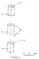
- Figure 1 shows a tip N with a notch H formed by flank faces each having an outer flank surface K.
- a root curve J curves into inner flank surfaces I which lead in turn into the outer flank surfaces K.
- the tip combines a number of important variables:-
- FIG. 2 shows three possible land configurations.
- E depicts a tip with a flat land X of infinite radius.
- F is a tip with a land of constant radius Y.
- G shows a tip with a land of changing radii Z
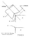
- FIG 3 shows how a tip N is configured with a holder M and a drive unit L.
- the tip N is held in the holder M and the reciprocating drive unit L provides the impacting action.
- the tip is offered against the workpiece edge using the outer flank surfaces of the notch for guidance.
- Figure 4 illustrates the principle of operation.
- the tip N impacts against the edge of the workpiece P, bending over any protrusion S encountered.
- the tip continues to impact until the inner flank surfaces beat the protrusion sufficiently thin that it breaks, tears or is driven off.
- the tip still continues to impact against the edge until the finish T conforms to the finish provided for by the "root curve".
- the device is traversed along the edge of the workpiece until the desired finish is obtained. This is done by hand or by machine. Alternatively the device is fixed in position and the workpiece moved across the tip.
Abstract
Description
- The present invention relates to the finishing-off of edges on workpieces by the smoothing of existing edges by the removal of burrs, sharp edges, fettles or other protrusions through peening and/or breaking away of the unwanted material on the edge prior to forming a clean smooth edge.
- Edge finishing and deburring are operations that must be carried out on many objects after they have been machined, cut or otherwise formed. At present these operations are carried out by hand (by filing or scraping), by grinding, by chemical erosion methods or by some other means. In particular, United States Patent No. 3,707,087 discloses finishing a workpiece edge by reciprocating a tip against the edge, the patent disclosing an edge-finishing device for finishing the edge of a workpiece comprising a tip for reciprocation against the edge, the tip having a notch with flank faces formed into its end. In operation the notched end of the tip is impacted against a workpiece edge, the reciprocating action being provided by a prime mover.
- According to the present invention there is provided an edge-finishing device for finishing the edge of a workpiece comprising a tip for reciprocation against the edge, the tip having a notch, the notch having a base that has a curved surface and further having outer flank surfaces which serve to guide the tip initially onto the workpiece edge, characterised in that the notch has curved inner flank surfaces which serve to beat a burr or protrusion thin enough to be broken or driven off from the edge. Preferably, the curved surface of the base of the notch determines, in use, the finish given to the edge of the workpiece.
- The present invention further provides a method of finishing a workpiece edge, in which there is reciprocated against the edge a tip of an edge-finishing device, the tip having a notch, the notch having a base that has a curved surface, and further having outer flank surfaces for guiding the tip onto the workpiece edge, characterised in that the notch has curved inner flank surfaces, the said inner flank surfaces beating burrs or protrusions thin enough that they are broken or driven off the edge, and the curved surface of the base of the notch determining the edge finish.
- For a better understanding of the invention and to show how the same may be carried out into effect, reference will now be made, by way of example, to the accompanying drawings, in which:-
- Figure 1
- shows in side, end, section and isometric view a tip;
- Figure 2
- shows a section three possible land configurations for a tip;
- Figure 3
- shows one of the tips fitted in a holder; and,
- Figure 4
- illustrates operation.
- Figure 1 shows a tip N with a notch H formed by flank faces each having an outer flank surface K. A root curve J curves into inner flank surfaces I which lead in turn into the outer flank surfaces K.
- The tip combines a number of important variables:-
- 1. Land Surface
This provides for a contact area (land) onto the workpiece edge. The land surface has a radius which would, typically, be 20 mm. Generally the harder the material to be finished the lesser the contact area or land required and, thus, the lesser the land surface radius required. - 2. Flanks
The outer flank surfaces help initially to guide the tip onto the workpiece edge. The outer flank surfaces lead into the inner flank surfaces. The inner flank surfaces have a radius which would, typically, be 1 mm. - 3. "Root Curve"
This is the curved surface at the base of the notch that strikes the workpiece edge and determines the finish given. The "root curve" has a radius which would, typically, be 0.25 mm. - Figure 2 shows three possible land configurations. E depicts a tip with a flat land X of infinite radius. F is a tip with a land of constant radius Y. G shows a tip with a land of changing radii Z
- In typical use a suitable tip is selected and mounted into the holder. Figure 3 shows how a tip N is configured with a holder M and a drive unit L. The tip N is held in the holder M and the reciprocating drive unit L provides the impacting action. The tip is offered against the workpiece edge using the outer flank surfaces of the notch for guidance. Figure 4 illustrates the principle of operation. The tip N impacts against the edge of the workpiece P, bending over any protrusion S encountered. The tip continues to impact until the inner flank surfaces beat the protrusion sufficiently thin that it breaks, tears or is driven off. The tip still continues to impact against the edge until the finish T conforms to the finish provided for by the "root curve".
- The device is traversed along the edge of the workpiece until the desired finish is obtained. This is done by hand or by machine. Alternatively the device is fixed in position and the workpiece moved across the tip.
Claims (3)
- An edge-finishing device for finishing the edge of a workpiece (P), comprising a tip (N) for reciprocation against the edge, the tip having a notch (H) the notch having a base that has a curved surface and further having outer flank surfaces (K) which serve to guide the tip initially onto the workpiece edge, characterised in that the notch (H) has curved inner flank surfaces (I) which serve to beat a burr or protrusion (S) thin enough to be broken or driven off from the edge.
- An edge-finishing device as claimed in claim 1, wherein, in use, the curved surface of the base of the notch determines the finish given to the edge of the workpiece.
- A method of finishing a workpiece edge, in which there is reciprocated against the edge a tip of an edge-finishing device, the tip having a notch, the notch having a base that has a curved surface, and further having outer flank surfaces for guiding the tip onto the workpiece edge, characterised in that the notch has curved inner flank surfaces, the said inner flank surfaces beating burrs or protrusions thin enough that they are broken or driven off the edge, and the curved surface of the base of the notch determining the edge finish.
Priority Applications (1)
| Application Number | Priority Date | Filing Date | Title |
|---|---|---|---|
| AT87900217T ATE78199T1 (en) | 1985-12-19 | 1986-12-18 | METHOD AND DEVICE FOR EDGE PROCESSING. |
Applications Claiming Priority (4)
| Application Number | Priority Date | Filing Date | Title |
|---|---|---|---|
| GB8531222 | 1985-12-19 | ||
| GB858531222A GB8531222D0 (en) | 1985-12-19 | 1985-12-19 | Burr removing device |
| GB8618523 | 1986-07-30 | ||
| GB868618523A GB8618523D0 (en) | 1985-12-19 | 1986-07-30 | Edge finishing device |
Publications (2)
| Publication Number | Publication Date |
|---|---|
| EP0289501A1 EP0289501A1 (en) | 1988-11-09 |
| EP0289501B1 true EP0289501B1 (en) | 1992-07-15 |
Family
ID=26290137
Family Applications (1)
| Application Number | Title | Priority Date | Filing Date |
|---|---|---|---|
| EP87900217A Expired - Lifetime EP0289501B1 (en) | 1985-12-19 | 1986-12-18 | Method and device for edge-finishing |
Country Status (7)
| Country | Link |
|---|---|
| US (1) | US5007268A (en) |
| EP (1) | EP0289501B1 (en) |
| AT (1) | ATE78199T1 (en) |
| AU (1) | AU601711B2 (en) |
| DE (1) | DE3686056T2 (en) |
| GB (1) | GB2206827B (en) |
| WO (1) | WO1987003830A1 (en) |
Families Citing this family (2)
| Publication number | Priority date | Publication date | Assignee | Title |
|---|---|---|---|---|
| CN110842095B (en) * | 2019-11-21 | 2022-12-23 | 徐州欧百瑞智能设备有限公司 | Pressing plate for trimming equipment protection skin |
| JP2022082982A (en) * | 2020-11-24 | 2022-06-03 | 株式会社セブンティ・エイト | Scraper |
Family Cites Families (8)
| Publication number | Priority date | Publication date | Assignee | Title |
|---|---|---|---|---|
| FR1160456A (en) * | 1956-10-31 | 1958-07-16 | Percussion forging | |
| US3150888A (en) * | 1962-05-08 | 1964-09-29 | Ingersoll Rand Co | Coupling means |
| US3707087A (en) * | 1971-06-16 | 1972-12-26 | Hildaur L Neilsen | Deburring devices |
| US3866452A (en) * | 1974-04-29 | 1975-02-18 | Hildaur L Neilsen | Deburring device |
| US3937055A (en) * | 1974-11-06 | 1976-02-10 | The United States Of America As Represented By The United States National Aeronautics And Space Administration | Method of peening and portable peening gun |
| US3926031A (en) * | 1975-01-23 | 1975-12-16 | Hildaur L Neilsen | Deburring device with oppositely acting deburring elements |
| SE436988B (en) * | 1983-07-01 | 1985-02-04 | Nilsson Goran Alfred | NAL HACK DEVICE NAL HACK DEVICE |
| DE3442089C1 (en) * | 1984-11-17 | 1985-11-14 | Messerschmitt-Bölkow-Blohm GmbH, 8012 Ottobrunn | Device for generating mechanical surface tensions |
-
1986
- 1986-12-18 AU AU67785/87A patent/AU601711B2/en not_active Ceased
- 1986-12-18 GB GB8814499A patent/GB2206827B/en not_active Expired - Lifetime
- 1986-12-18 WO PCT/GB1986/000777 patent/WO1987003830A1/en active IP Right Grant
- 1986-12-18 DE DE8787900217T patent/DE3686056T2/en not_active Expired - Fee Related
- 1986-12-18 AT AT87900217T patent/ATE78199T1/en active
- 1986-12-18 EP EP87900217A patent/EP0289501B1/en not_active Expired - Lifetime
-
1990
- 1990-02-05 US US07/477,186 patent/US5007268A/en not_active Expired - Fee Related
Also Published As
| Publication number | Publication date |
|---|---|
| GB2206827B (en) | 1990-01-10 |
| DE3686056T2 (en) | 1993-02-25 |
| AU601711B2 (en) | 1990-09-20 |
| DE3686056D1 (en) | 1992-08-20 |
| AU6778587A (en) | 1987-07-15 |
| GB2206827A (en) | 1989-01-18 |
| GB8814499D0 (en) | 1988-07-27 |
| EP0289501A1 (en) | 1988-11-09 |
| ATE78199T1 (en) | 1992-08-15 |
| US5007268A (en) | 1991-04-16 |
| WO1987003830A1 (en) | 1987-07-02 |
Similar Documents
| Publication | Publication Date | Title |
|---|---|---|
| US6872125B2 (en) | Tool for smoothing a workpiece | |
| US4625725A (en) | Surgical rasp and method of manufacture | |
| US6220139B1 (en) | Saw blade | |
| CA2003735C (en) | Deburring tool with cutting blades | |
| EP0203085B1 (en) | Cutting tool and method of manufacture | |
| US8408972B2 (en) | Apparatus and method for intricate cuts | |
| EP0776259A1 (en) | Saw blade tooth form and method therefor | |
| US5669744A (en) | Rotary chisel | |
| EP0289501B1 (en) | Method and device for edge-finishing | |
| US6971949B2 (en) | Sharpening guide for dental tools | |
| US20020078813A1 (en) | Saw blade | |
| EP1382414B1 (en) | Method of making a cutting tool blade | |
| EP1179997B1 (en) | Abrasive tool having safe and active areas | |
| WO1992002345A1 (en) | Chisel for dust-free chasing of brick structures | |
| RU2294819C1 (en) | Flat surfaces pulse milling method with use of needle milling cutter | |
| GB2195928A (en) | Method of cutting a surface of a work-piece | |
| RU2050225C1 (en) | Method for grinding by tool with two intersecting chipping facets | |
| RU2055703C1 (en) | Intermittent needle milling method | |
| RU2131803C1 (en) | Elongate flat product grinding method | |
| SU722685A1 (en) | Chip breaking method | |
| SU1060315A1 (en) | Method of machining holes | |
| SU1673400A1 (en) | Method for sharpening blades | |
| JPH07237136A (en) | Grinding wheel and cutting device | |
| CA1329988C (en) | Ultrasonic polishing | |
| SU1038200A2 (en) | Method of finishing limited flat surfaces by honing stick |
Legal Events
| Date | Code | Title | Description |
|---|---|---|---|
| PUAI | Public reference made under article 153(3) epc to a published international application that has entered the european phase |
Free format text: ORIGINAL CODE: 0009012 |
|
| 17P | Request for examination filed |
Effective date: 19880620 |
|
| AK | Designated contracting states |
Kind code of ref document: A1 Designated state(s): AT BE CH DE FR GB IT LI NL SE |
|
| 17Q | First examination report despatched |
Effective date: 19900214 |
|
| DIN1 | Information on inventor provided before grant (deleted) | ||
| RAP1 | Party data changed (applicant data changed or rights of an application transferred) |
Owner name: ORIGINATIONS LIMITED Owner name: KELLY, NIGEL B. |
|
| ITTA | It: last paid annual fee | ||
| GRAA | (expected) grant |
Free format text: ORIGINAL CODE: 0009210 |
|
| AK | Designated contracting states |
Kind code of ref document: B1 Designated state(s): AT BE CH DE FR IT LI NL SE |
|
| PG25 | Lapsed in a contracting state [announced via postgrant information from national office to epo] |
Ref country code: SE Effective date: 19920715 Ref country code: LI Effective date: 19920715 Ref country code: CH Effective date: 19920715 Ref country code: BE Effective date: 19920715 Ref country code: AT Effective date: 19920715 |
|
| REF | Corresponds to: |
Ref document number: 78199 Country of ref document: AT Date of ref document: 19920815 Kind code of ref document: T |
|
| RIN1 | Information on inventor provided before grant (corrected) |
Inventor name: KELLY, NIGEL B. |
|
| ITF | It: translation for a ep patent filed |
Owner name: BARZANO' E ZANARDO ROMA S.P.A. |
|
| REF | Corresponds to: |
Ref document number: 3686056 Country of ref document: DE Date of ref document: 19920820 |
|
| ET | Fr: translation filed | ||
| REG | Reference to a national code |
Ref country code: CH Ref legal event code: PL |
|
| PGFP | Annual fee paid to national office [announced via postgrant information from national office to epo] |
Ref country code: NL Payment date: 19921231 Year of fee payment: 7 Ref country code: FR Payment date: 19921231 Year of fee payment: 7 |
|
| PGFP | Annual fee paid to national office [announced via postgrant information from national office to epo] |
Ref country code: DE Payment date: 19930129 Year of fee payment: 7 |
|
| PLBE | No opposition filed within time limit |
Free format text: ORIGINAL CODE: 0009261 |
|
| STAA | Information on the status of an ep patent application or granted ep patent |
Free format text: STATUS: NO OPPOSITION FILED WITHIN TIME LIMIT |
|
| 26N | No opposition filed | ||
| PG25 | Lapsed in a contracting state [announced via postgrant information from national office to epo] |
Ref country code: NL Effective date: 19940701 |
|
| NLV4 | Nl: lapsed or anulled due to non-payment of the annual fee | ||
| PG25 | Lapsed in a contracting state [announced via postgrant information from national office to epo] |
Ref country code: FR Effective date: 19940831 |
|
| PG25 | Lapsed in a contracting state [announced via postgrant information from national office to epo] |
Ref country code: DE Effective date: 19940901 |
|
| REG | Reference to a national code |
Ref country code: FR Ref legal event code: ST |
|
| PG25 | Lapsed in a contracting state [announced via postgrant information from national office to epo] |
Ref country code: IT Free format text: LAPSE BECAUSE OF NON-PAYMENT OF DUE FEES;WARNING: LAPSES OF ITALIAN PATENTS WITH EFFECTIVE DATE BEFORE 2007 MAY HAVE OCCURRED AT ANY TIME BEFORE 2007. THE CORRECT EFFECTIVE DATE MAY BE DIFFERENT FROM THE ONE RECORDED. Effective date: 20051218 |