EP0288706A2 - Jigging conveyor - Google Patents
Jigging conveyor Download PDFInfo
- Publication number
- EP0288706A2 EP0288706A2 EP88103954A EP88103954A EP0288706A2 EP 0288706 A2 EP0288706 A2 EP 0288706A2 EP 88103954 A EP88103954 A EP 88103954A EP 88103954 A EP88103954 A EP 88103954A EP 0288706 A2 EP0288706 A2 EP 0288706A2
- Authority
- EP
- European Patent Office
- Prior art keywords
- webs
- stator
- vibratory conveyor
- sheet metal
- plate
- Prior art date
- Legal status (The legal status is an assumption and is not a legal conclusion. Google has not performed a legal analysis and makes no representation as to the accuracy of the status listed.)
- Withdrawn
Links
Images


Classifications
-
- B—PERFORMING OPERATIONS; TRANSPORTING
- B65—CONVEYING; PACKING; STORING; HANDLING THIN OR FILAMENTARY MATERIAL
- B65G—TRANSPORT OR STORAGE DEVICES, e.g. CONVEYORS FOR LOADING OR TIPPING, SHOP CONVEYOR SYSTEMS OR PNEUMATIC TUBE CONVEYORS
- B65G27/00—Jigging conveyors
- B65G27/08—Supports or mountings for load-carriers, e.g. framework, bases, spring arrangements
-
- B—PERFORMING OPERATIONS; TRANSPORTING
- B65—CONVEYING; PACKING; STORING; HANDLING THIN OR FILAMENTARY MATERIAL
- B65G—TRANSPORT OR STORAGE DEVICES, e.g. CONVEYORS FOR LOADING OR TIPPING, SHOP CONVEYOR SYSTEMS OR PNEUMATIC TUBE CONVEYORS
- B65G27/00—Jigging conveyors
- B65G27/10—Applications of devices for generating or transmitting jigging movements
- B65G27/16—Applications of devices for generating or transmitting jigging movements of vibrators, i.e. devices for producing movements of high frequency and small amplitude
- B65G27/24—Electromagnetic devices
Definitions
- the invention relates to an oscillating conveyor with an oscillating plate suitable for receiving a container, for example, with the oscillating plate providing an oscillating movement with a main conveying direction, electromagnetic drive means in the form of oscillating armature motors, which includes a stationary stator, an armature firmly connected to the oscillating plate and one from a power source
- electromagnetic drive means in the form of oscillating armature motors, which includes a stationary stator, an armature firmly connected to the oscillating plate and one from a power source
- Have alternating current or pulsating direct current feedable excitation coil which is placed on a pole piece of the stator bearing a stator pole face interacting with an armature pole face, and with spring means by which the oscillating plate is supported elastically in a horizontally and vertically limited manner.
- the oscillating armature motors which serve to drive the oscillating plate are combined with elongated leaf spring assemblies assigned to them to form a drive assembly.
- Several such drive assemblies are formed between one with an additional mass Chassis or base frame and the swing plate arranged.
- the spatial orientation in which the structural units are anchored to the common oscillating plate is critical because of the vibration behavior of the individual drive structural units, which is predetermined by the spatial assignment of the active pole faces to the leaf spring assemblies.
- the drive assemblies require an additional precise adjustment and adjustment during assembly, which is complicated and time-consuming.
- a more favorable arrangement of the spring elements has a drive unit known from DE-OS 2051 573 for generating simultaneous lifting and torsional vibrations, in particular for spiral conveyors with two parts which are movable relative to one another, in which these two parts and the connecting elements of these parts forming the spring elements are combined into a body made of plastic.
- This plastic body has essentially the shape of a pot with a perforated pot wall, the annular pot edge of which is formed by one of the two parts, the perforated pot wall by the connecting or spring elements and the pot base by the other of the two parts.
- the plastic body must be accommodated in a pot-like sleeve connected to the chassis. The formation of a linear conveyor is not possible in this way.
- the object of the invention is to provide an oscillating conveyor which is characterized by a particularly simple construction of the resilient mounting of the oscillating plate, the associated spring elements being easy to manufacture with high precision and the suspension devices overall being able to be assembled with little effort, in particular also with regard to the adjustment .
- the above-mentioned vibratory conveyor is characterized according to the invention in that the spring means are formed by narrow, spring-elastic webs of a sheet metal or thin material strip having recesses, through the recesses of which the webs are delimited and on the vibrating plate and the stators or the stator or a base plate carrying this or these is attached.
- the recesses can advantageously be punched out or cut out, which can be done in an automatic workflow by means of a suitable tool.
- the individual webs are fixed in the sheet metal or material strip in exact mutual spatial association, so that particularly simple assembly conditions also result because the sheet metal strip only needs to be attached to the oscillating plate and, for example, the base plate.
- the webs can also be appropriately twisted about their longitudinal axis in such a way that they lie over a part of their length in planes which enclose a predetermined angle of less than 90 ° with the plane of the sheet metal or strip of material.
- the suspension properties can also be influenced by appropriate dimensioning of the twisted area and the torsion angle, while at the same time a favorable loading of the webs can be achieved.
- the webs can be twisted without any problems using an appropriate follow-up tool during the punching process.
- the recesses are advantageous to arrange at equal intervals, so that webs of the same width and evenly distributed are also obtained.
- the webs themselves are inclined in one direction with respect to the oscillating plate with the same orientation, in such a way that they are connected to the oscillating plate enclose an angle of less than 90 °. This results in very simple and favorable drive conditions for the vibrating armature motors.
- the webs are arranged at right angles to the oscillating plate and are elastically deflected from this initial position by the oscillating plate, which is driven by the oscillating armature motors.
- the sheet metal or material strip containing the webs can be flat, wherein, as explained above, the webs can be twisted about their longitudinal axis; it is bent for a circular conveyor according to the circular shape of the vibrating plate, while straight pieces of strip are used in a linear conveyor.
- the arrangement can also be such that the sheet metal or material strip is corrugated in the longitudinal direction or curved in a meandering shape to form waves or trough-shaped depressions extending from the oscillating plate to the stators or the stator or the base plate.
- the stiffness is due to the corrugation or meandering bend of the sheet metal or material strip changed, so that spring properties of the webs also result with simple means, which have proven to be advantageous for many purposes.
- the webs are formed in the wall areas of the shafts or channel-shaped depressions arranged transversely to the edge of the oscillating plate, so that the webs lie in the "walls" of the shafts or depressions which are essentially transverse to the edge of the oscillating plate, ie one have similar orientation as the twisted webs explained at the beginning.
- the sheet metal strip advantageously consists of spring steel, the recesses being punched out in the case of soft annealed material, in particular in the case of larger sheet metal thicknesses, and the sheet metal strip is subsequently hardened.
- the material strip consists of a plastic material are also conceivable.
- the recesses and the webs delimited thereby are formed, but it is also conceivable, for example in the case of flat, non-twisted webs, to punch or cut out the recesses from the material strip.
- the sheet metal or material strip is fastened to the oscillating plate and / or the base plate on an edge-side, continuous fastening area which extends outside the recesses delimiting the webs. This results in very simple conditions if the sheet metal or material strip on the Side wall of the vibrating plate, for example. Is fastened by means of screws or welding or another suitable type of fastening.
- the vibratory conveyor shown in FIGS. 1,2 is a so-called circular conveyor. It has a circular metallic oscillating plate 1, on which a coaxial pot-shaped container 2 is arranged, on the inner wall of which are indicated by 3 ridges arranged in a helical manner, on which bulk goods introduced into the container 2, for example small screws, under the effect of the Swing plate 1 issued swing movement in a known manner to move upwards.
- a metallic coaxial base plate 4 which is set up on a base by means of rubber-metal feet 5 and carries two oscillating armature motors 6 on its upper side, the basic structure of which can be seen in FIG. 2:
- Each of the oscillating armature motors 6 has an essentially trapezoidal, laminated stator laminated core 7, which is provided with an opening 8 with a rectangular cross section, which is partially delimited on one side by the plane pole face 9, parallel to this side, of a cut pole piece 10.
- the width of the opening 8 measured at right angles to the pole face 9 is selected such that the excitation coil 12 can be inserted into the opening 8 and pushed onto the pole piece 10 from there.
- the two laminated cores 7 are abutted with their largest broad sides and aligned along a diameter 13 of the base plate 1, screwed to the base plate 1 by means of screw bolts indicated at 14 and pressed together at the same time.
- the arrangement is such that the two pole faces 9 are aligned parallel to the diameter 15 which intersects the diameter 13 at right angles and are at the same distance from it - but on different sides of this diameter 15 - as can be seen in FIG. 2 is.
- an air gap 17 is present between the pole face 9 and the opposite armature pole face, the size of which is set depending on whether the vibrating plate 1 works according to the so-called "tablecloth pull-off effect” or the so-called "throwing effect".
- the oscillating plate 1 is supported against the base plate 4 by means of spring elements which are movable horizontally and vertically to a limited extent and which are formed by cut-off webs 18 of a cylindrically curved spring plate strip 19.
- the spring metal strip 19 has a uniform length over its length distributed, identically shaped recesses 20, which were punched into the flat spring sheet strips 19.
- the elongated recesses 20 are laterally delimited with parallel flanks over most of their length; they in turn limit the webs 18 between them, which can be seen to be of the same design (FIG. 6).
- the webs 18 are twisted over a major part of their longitudinal extent, designated 21, in such a way that they enclose an angle of 90 ° with the sheet metal strip plane in this area. This angle is designated 22 in FIG. 2.
- the webs 18 of the same design are arranged equally inclined in one direction such that they enclose an angle of less than 90 ° with the horizontal plane 23 containing the top and bottom of the oscillating plate 1, which in a practical embodiment is of the order of magnitude of approximately 70 ° and is designated by 24 in FIG.
- a continuous strip-like fastening region 25 is formed on the edge side, which contains holes 26 arranged in an evenly distributed manner, through which fastening screws 27 run in the assembled state (FIG. 1) by means of of which the spring sheet metal strip 19 is screwed to a corresponding peripheral wall area of the oscillating plate 1 and the base plate 4.
- the butt abutting edges of the cylindrically curved spring plate strip 19 are generally not connected to one another; a connection, for example by welding, is conceivable in individual cases.
- the pole faces 9 attract the opposing armature plate assemblies 16, with the result that the oscillating plate, in relation to FIG. 2, is given a counterclockwise rotary movement.
- the inclined spring elements formed by the webs 18 are correspondingly deformed and thus placed under prestress. As soon as the excitation of the excitation coils 12 disappears, this elastic prestressing of the webs 18 leads the oscillating plate 1 back to its starting position in a rapid movement in a clockwise direction.
- the vibratory conveyor shown in FIGS. 3 to 5 is designed as a linear conveyor and constructed according to the same principle as the circular conveyor already described according to FIGS. 1 and 2. The same or corresponding parts are therefore provided with the same reference numerals and are not explained again.
- the oscillating plate 1a and the base plate 4a arranged parallel to it at a distance have a rectangular, strip-like shape with mutually opposite parallel sides.
- the base plate 4a is placed on a base via rubber metal feet 5a.
- the vibrating plate 1a carries an elongated vibrating or conveying trough 2a.
- a common stator 7a Arranged on the base plate 4a is a common stator 7a in the form of an elongated laminated core which is rectangular in cross section and layered from flat-lying dynamo sheet strips and is screwed to the base plate 4 by means of screw bolts (not shown).
- the stator 7a is formed with two openings 8a which are symmetrical to the longitudinal center line of the base plate 4 and are at a distance from one another and which are rectangular in cross section and which are delimited on one side, similarly to FIG. 2, by vertical pole faces 9a cut at right angles to the base plate 4a .
- the excitation coils 12a are pushed onto the pole pieces 10a; the width of the openings 8a is again matched to the axial height of the excitation coils 12a in such a way that they can be introduced into the openings and can be pushed onto the pole pieces 10a from them.
- a block-like anchor plate pack 16a with parallel flanks is protruding, which is also layered from corresponding dynamo sheet pieces and is fastened to the oscillating plate 1a by means of screw bolts (not shown).
- a trough-shaped container which is not shown further, can be arranged on the oscillating plate 1a itself.
- the vibrating plate 1 a is supported against the base plate 4 a by means of spring elements which are horizontally and vertically limited to a limited extent and which are formed by the webs 18 of the spring plate strip 19 which have already been explained.
- Two pieces of the spring plate strip 19 according to FIG. 6 cut off according to the length of the base plate 4a are in this case attached by means of the screws 27a to the opposing longitudinal side walls of the vibrating plate 1a and the base plate 4a.
- the webs 18 of both spring sheet metal strip pieces 19 are inclined in the same direction with respect to the horizontal plane 23.
- the armature pole faces are at a predetermined distance 17 from the stator pole faces 9a opposite them in parallel.
- the vibrating plate 1a is moved to the left, based on FIG. 4, the webs 18 being elastically deformed.
- the webs 18 can move the oscillating plate 1 a to the right in a rapid stroke movement, based on FIG. 4, under the effect of their elastic prestress, so that a reciprocating oscillating movement of the oscillating plate 1 a in the arrangement shown in FIG. 4 results in the main conveying direction lying in the horizontal plane of the drawing.
- the number of vibration armature motors formed in each case by a stator pole piece 10a with the excitation coil 12a and the associated armature lamination stack 16a is not limited; it can also be chosen to be larger than 2 in accordance with the dimensions and the desired drive power of the vibratory conveyor, as are also conceivable embodiments which only have such a vibratory armature motor.
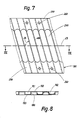
- FIG. 78 shows a modified embodiment of the spring sheet metal strip 19 according to FIG. 6.
- the spring sheet metal strip 190 is bent in a meandering manner in the longitudinal direction of the strip, as can be seen from FIG. 8.
- essentially rectangular recesses 191 are formed in cross-section, which have a rectangular cross-sectional shape at the same angle 24, inclined to the horizontal plane 23 parallel to the oscillating plate 1 or 1a, and which alternate with the oscillating plate 1, 1a and the base plate 4, 4a and open it on the opposite outside.
- the spring sheet metal strip 190 could also be corrugated, as is indicated by the broken line at 192 in FIG. 8.
- the elongated depressions 191 are then curved in cross section in an arc shape, for example in the form of a part circle.
- the elongated, laterally parallel flanking recesses 200 are again formed at regular intervals and in the same design and orientation. They lie, as can be seen from FIG. 8, in the wall regions 193 which are aligned parallel to the side surfaces of the oscillating plate 1, 1a and the base plate 4,4a in the assembled state of the spring sheet metal strip 190. This in turn means that the webs 180 in the transverse to the Wall regions of the shafts 192 or the groove-like depressions 191 are aligned with the oscillating plate edge.
- the spring metal strips 19, 190 can be directly punched and bent with a small sheet thickness. In the case of a larger sheet thickness, it is advisable to punch and bend the sheet metal strips in the soft material state and then to harden the finished sheet metal strips.
- the thin strips of material 19, 190 are made from a plastic material which has corresponding suspension properties.
- the spring sheet metal strips 19, 190 can finally also be used to hold an elastic sealing sleeve extending between the vibrating plate 1, 1a and the base plate 4, 4a, which is arranged between the sheet metal strips and the associated side wall of the vibrating or base plate and through which Fastening areas 25, 250 is clamped.
- This basic arrangement is illustrated schematically in FIG. 9, where the rubber sleeve is indicated at 30.
- the rubber sleeve 30 is in an edge-side recess 31 of the vibrating plate 1 and corresponding to the base plate 4, not shown; it is clamped by the spring plate strips 19 and 190, which are correspondingly profiled in the fastening area 25 and 250, respectively.
- the vibratory conveyors described on the basis of the exemplary embodiments explained have special vibratory armature motors which are formed with layered stator and armature laminate stacks.
- the invention is not limited to vibratory conveyors with vibratory armature motors designed in this way; it is basically usable for all vibratory conveyors where it is important to support an oscillating plate that is set in oscillatory motion by drive means in a spring-elastic manner against a base plate or a stationary anchoring.
- the spring plate or material strips 19 or 190 are not fastened to a base plate 4 or 4a on the side facing away from the oscillating plate, but rather directly to the stators 7 and the stator 7a.
- a cylindrical stator configuration or arrangement can be advantageous for this.
- the inertial mass required for the stability, connected to the base plate 4 or 4a, is formed directly by the stator laminations 7 or 7a, so that additional masses are unnecessary. If necessary, such additional masses can be provided; they can also be indispensable for other vibration armature motor designs.
- the base plate 4 or 4a can be part of a chassis be or base frame or be formed in whole or in part by such, regardless of whether it is flat or, for example, pot-shaped, etc.
- the circular conveyor described (FIGS. 1, 2) can be set up for clockwise or counter-clockwise rotation using the parts explained, including the sheet metal or material strips 19, depending on the conditions of the respective application. All that is required is to arrange the laminated stator laminations 7 and the sheet metal or material strips 19 in accordance with the direction of travel desired in each case.
- the sheet metal or material strips 19 can be practically of any length, circular conveyors of any diameter and in particular also linear conveyors of very great length can be produced. In individual cases, it is also conceivable to subdivide the sheet metal or material strips 19 into individual strip sections which are butted against one another and which, if necessary, can also be connected to one another, for example welded or riveted.
Abstract
Description
Die Erfindung betrifft einen Schwingförderer mit einer bspw. zur Aufnahme eines Behälters geeigneten Schwingplatte, mit der Schwingplatte eine Schwingbewegung mit einer Hauptförderrichtung erteilenden elektromagnetischen Antriebsmitteln in Gestalt von Schwingankermotoren, die einen ortsfesten Stator, einen mit der Schwingplatte fest verbundenen Anker und eine aus einer Stromquelle mit Wechselstrom oder pulsierendem Gleichstrom speisbare Erregerspule aufweisen, welche auf ein eine mit einer Ankerpolfläche zusammenwirkende Statorpolfläche tragendes Polstück des Stators aufgesetzt ist, sowie mit Federmitteln, durch die die Schwingplatte horizontal und vertikal begrenzt beweglich elastisch abgestützt ist.The invention relates to an oscillating conveyor with an oscillating plate suitable for receiving a container, for example, with the oscillating plate providing an oscillating movement with a main conveying direction, electromagnetic drive means in the form of oscillating armature motors, which includes a stationary stator, an armature firmly connected to the oscillating plate and one from a power source Have alternating current or pulsating direct current feedable excitation coil which is placed on a pole piece of the stator bearing a stator pole face interacting with an armature pole face, and with spring means by which the oscillating plate is supported elastically in a horizontally and vertically limited manner.
Bei einem aus der US-PS 3048 260 sowohl in einer Ausführung als Kreisförderer als auch in einer Ausführung als Linearförderer bekannten Schwingförderer sind die zum Antrieb der Schwingplatte dienenden Schwingankermotoren mit ihnen zugeordneten länglichen Blattfederpaketen jeweils zu einer Antriebs-Baueinheit zusammengefaßt. Mehrere solcher Antriebs-Baueinheiten sind zwischen einem mit einer Zusatzmasse ausgebildeten Chassis oder Grundgestell und der Schwingplatte angeordnet. Wegen des durch die räumliche Zuordnung der aktiven Polflächen zu den Blattfederpaketen vorgegebenen Schwingungsverhaltens der einzelnen Antriebs-Baueinheiten ist die räumliche Ausrichtung, in der die Baueinheiten an der gemeinsamen Schwingplatte verankert sind, kritisch. Um das Auftreten toter Zonen oder von Nachteilen hinsichtlich des Wirkungsgrades zu vermeiden, erfordern die Antriebs-Baueinheiten bei ihrer Montage eine zusätzliche genaue Abstimmung und Einjustierung, was umständlich und aufwendig ist.In an oscillating conveyor known from US Pat. No. 3,048,260, both in an embodiment as a circular conveyor and in an embodiment as a linear conveyor, the oscillating armature motors which serve to drive the oscillating plate are combined with elongated leaf spring assemblies assigned to them to form a drive assembly. Several such drive assemblies are formed between one with an additional mass Chassis or base frame and the swing plate arranged. The spatial orientation in which the structural units are anchored to the common oscillating plate is critical because of the vibration behavior of the individual drive structural units, which is predetermined by the spatial assignment of the active pole faces to the leaf spring assemblies. In order to avoid the occurrence of dead zones or disadvantages in terms of efficiency, the drive assemblies require an additional precise adjustment and adjustment during assembly, which is complicated and time-consuming.
Eine günstigere Anordnung der Federelemente weist demgegenüber ein aus der DE-OS 2051 573 bekanntes Antriebsaggregat zur Erzeugung von gleichzeitigen Hub- und Drehschwingungen, insbesondere für Wendelförderer mit zwei relativ zueinander beweglichen Teilen auf, bei dem diese beiden Teile und die die Federelemente bildenden Verbindungselemente dieser Teile zu einem aus Kunststoff bestehenden Körper zusammengefaßt sind. Dieser Kunststoffkörper hat im wesentlichen die Form eines Topfes mit durchbrochener Topfwand, dessen ringförmiger Topfrand von dem einen der beiden Teile, dessen durchbrochene Topfwand von den Verbindungs- oder Federelementen und dessen Topfboden von dem anderen der beiden Teile gebildet ist. Abgesehen davon, daß der einstückige, topfförmige Kunststoffkörper zu seiner Herstellung aufwendige und komplizierte Formen erfordert, muß der Kunststoffkörper in einer mit dem Chassis verbundenen topfartigen Hülse untergebracht sein. Die Ausbildung eines Linearförderers ist auf diese Weise nicht möglich.A more favorable arrangement of the spring elements, on the other hand, has a drive unit known from DE-OS 2051 573 for generating simultaneous lifting and torsional vibrations, in particular for spiral conveyors with two parts which are movable relative to one another, in which these two parts and the connecting elements of these parts forming the spring elements are combined into a body made of plastic. This plastic body has essentially the shape of a pot with a perforated pot wall, the annular pot edge of which is formed by one of the two parts, the perforated pot wall by the connecting or spring elements and the pot base by the other of the two parts. In addition to the fact that the one-piece, pot-shaped plastic body requires complex and complicated shapes for its production, the plastic body must be accommodated in a pot-like sleeve connected to the chassis. The formation of a linear conveyor is not possible in this way.
Aufgabe der Erfindung ist es, einen Schwingförderer zu schaffen, der sich durch einen besonders einfachen Aufbau der federelastischen Halterung der Schwingplatte auszeichnet, wobei die zugehörigen Federelemente mit hoher Präzision leicht herstellbar und die Federungseinrichtungen insgesamt mit geringem Aufwand, insbesondere auch hinsichtlich der Einjustierung, montierbar sind.The object of the invention is to provide an oscillating conveyor which is characterized by a particularly simple construction of the resilient mounting of the oscillating plate, the associated spring elements being easy to manufacture with high precision and the suspension devices overall being able to be assembled with little effort, in particular also with regard to the adjustment .
Zur Lösung dieser Aufgabe ist der eingangs genannte Schwingförderer erfindungsgemäß dadurch gekennzeichnet, daß die Federmittel durch schmale, federelastische Stege eines Ausnehmungen aufweisenden Blech- oder dünnen Materialstreifens gebildet sind, durch dessen Ausnehmungen die Stege begrenzt sind und der an der Schwingplatte und den Statoren oder dem Stator oder einer diese bzw. diesen tragenden Grundplatte befestigt ist.To achieve this object, the above-mentioned vibratory conveyor is characterized according to the invention in that the spring means are formed by narrow, spring-elastic webs of a sheet metal or thin material strip having recesses, through the recesses of which the webs are delimited and on the vibrating plate and the stators or the stator or a base plate carrying this or these is attached.
Die Ausnehmungen können mit Vorteil ausgestanzt oder ausgeschnitten sein, was mittels eines geeigneten Werkzeuges in einem automatischen Arbeitsablauf geschehen kann. In jedem Falle sind aber in dem Blechoder Materialstreifen die einzelnen Stege in exakter gegenseitiger räumlicher Zuordnung fixiert, so daß sich auch besonders einfache Montageverhältnisse ergeben, weil der Blechstreifen lediglich an der Schwingplatte und bspw. der Grundplatte befestigt zu werden braucht. Durch geeignete Materialwahl und zweckentsprechende Bemessung der Dicke und der die Länge der Stege bestimmenden Breite des Blech- oder Materialstreifens sowie der Umrißgestaltung der Ausnehmungen und deren Verteilung können praktisch beliebige Federungseigenschaften der federelastischen Abstützung der Schwingplatte erzielt werden.The recesses can advantageously be punched out or cut out, which can be done in an automatic workflow by means of a suitable tool. In any case, however, the individual webs are fixed in the sheet metal or material strip in exact mutual spatial association, so that particularly simple assembly conditions also result because the sheet metal strip only needs to be attached to the oscillating plate and, for example, the base plate. Through a suitable choice of material and appropriate dimensioning of the thickness and the width of the sheet metal or material strip, which determines the length of the webs, and the outline design of the recesses and their distribution can be achieved practically any suspension properties of the resilient support of the vibrating plate.
Auch können zweckmäßigerweise die Stege um ihre Längsachse verwunden sein, derart, daß sie über einen Teil ihrer Länge in Ebenen liegen, die mit der Blech- oder Materialstreifenebene einen vorbestimmten Winkel kleiner 90° einschließen. Durch entsprechende Bemessung des verwundenen Bereichs sowie des Verwindungswinkels lassen sich die Federungseigenschaften ebenfalls beeinflussen, wobei gleichzeitig auch eine günstige Belastung der Stege erreicht werden kann. Das Verwinden der Stege kann problemlos durch ein entsprechendes Folgewerkzeug beim Stanzvorgang erfolgen.The webs can also be appropriately twisted about their longitudinal axis in such a way that they lie over a part of their length in planes which enclose a predetermined angle of less than 90 ° with the plane of the sheet metal or strip of material. The suspension properties can also be influenced by appropriate dimensioning of the twisted area and the torsion angle, while at the same time a favorable loading of the webs can be achieved. The webs can be twisted without any problems using an appropriate follow-up tool during the punching process.
In der Regel ist es vorteilhaft, die Ausnehmungen in gleichen Abständen anzuordnen, so daß sich auch gleich breite und gleichmäßig verteilt angeordnete Stege ergeben. Es sind aber auch Ausführungsformen denkbar, bei denen mit Rücksicht auf die zu erzielenden Schwingungseigenschaften der Schwingplatte es zweckmäßig sein kann, die Ausnehmungen über die Länge des Blechstreifens unterschiedlich zu gestalten oder in verschiedenen Abständen anzuordnen, bspw. derart, daß Gruppen von Stegen gebildet werden, die dann wiederum durch eine größere Lücke voneinander getrennt sind. Die Stege selbst sind in einer bevorzugten Ausführungsform gegenüber der Schwingplatte mit gleicher Ausrichtung in einer Richtung geneigt angeordnet, derart, daß sie mit der Schwingplatte einen Winkel von kleiner 90° einschließen. Damit ergeben sich sehr einfache und günstige Antriebsverhältnisse für die Schwingankermotoren. Prinzipiell sind aber auch Ausführungsformen denkbar, bei denen die Stege rechtwinklig zu der Schwingplatte verlaufend angeordnet sind und von der von den Schwingankermotoren entsprechend angetriebenen Schwingplatte aus dieser Ausgangslage elastisch ausgelenkt werden.As a rule, it is advantageous to arrange the recesses at equal intervals, so that webs of the same width and evenly distributed are also obtained. However, embodiments are also conceivable in which, with regard to the vibration properties of the vibration plate to be achieved, it may be expedient to design the recesses differently over the length of the sheet metal strip or to arrange them at different intervals, for example in such a way that groups of webs are formed, which are then separated by a larger gap. In a preferred embodiment, the webs themselves are inclined in one direction with respect to the oscillating plate with the same orientation, in such a way that they are connected to the oscillating plate enclose an angle of less than 90 °. This results in very simple and favorable drive conditions for the vibrating armature motors. In principle, however, embodiments are also conceivable in which the webs are arranged at right angles to the oscillating plate and are elastically deflected from this initial position by the oscillating plate, which is driven by the oscillating armature motors.
Sehr einfache und übersichtliche Verhältnisse ergeben sich, wenn die länglichen Ausnehmungen zumindest im Bereiche der Stege parallelflankig begrenzt sind, so daß sich auch entsprechende, im Prinzip leistenartige Stege ergeben. Wie schon erwähnt, ist es auch häufig am einfachsten und übersichtlichsten, wenn alle Stege gleichgestaltet sind.Very simple and clear conditions result if the elongate recesses are delimited with parallel flanks, at least in the area of the webs, so that corresponding webs, which in principle are strip-like, also result. As already mentioned, it is often the simplest and clearest if all the bridges are of the same design.
Der die Stege enthaltende Blech- oder Materialstreifen kann eben sein, wobei, wie vorstehend erläutert, die Stege um ihre Längsachse verwunden sein können; er wird für einen Kreisförderer entsprechend der Kreisform der Schwingplatte gebogen, während bei einem Linearförderer gerade Streifenstücke Verwendung finden.The sheet metal or material strip containing the webs can be flat, wherein, as explained above, the webs can be twisted about their longitudinal axis; it is bent for a circular conveyor according to the circular shape of the vibrating plate, while straight pieces of strip are used in a linear conveyor.
In einer alternativen Ausführungsform kann die Anordnung aber auch derart getroffen sein, daß der Blech- oder Materialstreifen unter Ausbildung von von der Schwingplatte zu den Statoren oder dem Stator bzw. der Grundplatte verlaufenden Wellen oder rinnenförmigen Vertiefungen in Längsrichtung gewellt oder mäanderförmig gebogen ist. Durch die Wellung oder mäanderförmige Verbiegung wird die Steifigkeit des Blech- oder Materialstreifens verändert, so daß sich auch mit einfachen Mitteln Federeigenschaften der Stege ergeben, die für viele Einsatzzwecke sich als vorteilhaft erwiesen haben. Zweckmäßig ist es dabei, wenn die Stege in den quer zu der Schwingplattenberandung angeordneten Wandbereichen der Wellen oder rinnenförmigen Vertiefungen ausgebildet sind, so daß die Stege in den im wesentlichen quer zu der Berandung der Schwingplatte ausgerichteten "Wänden" der Wellen oder Vertiefungen liegen, d.h. eine ähnliche Orientierung aufweisen wie die eingangs erläuterten verwundenen Stege.In an alternative embodiment, however, the arrangement can also be such that the sheet metal or material strip is corrugated in the longitudinal direction or curved in a meandering shape to form waves or trough-shaped depressions extending from the oscillating plate to the stators or the stator or the base plate. The stiffness is due to the corrugation or meandering bend of the sheet metal or material strip changed, so that spring properties of the webs also result with simple means, which have proven to be advantageous for many purposes. It is expedient if the webs are formed in the wall areas of the shafts or channel-shaped depressions arranged transversely to the edge of the oscillating plate, so that the webs lie in the "walls" of the shafts or depressions which are essentially transverse to the edge of the oscillating plate, ie one have similar orientation as the twisted webs explained at the beginning.
In einigen geschilderten Ausführungsformen besteht der Blechstreifen mit Vorteil aus Federstahl, wobei insbesondere bei größeren Blechstärken die Ausnehmungen bei weichgeglühtem Material ausgestanzt werden und anschließend der Blechstreifen gehärtet wird. Insbesondere bei kleineren Schwingförderern sind aber auch Ausführungsforem denkbar, bei denen der Materialstreifen aus einem Kunststoffmaterial besteht. Dabei sind die Ausnehmungen und die davon begrenzten Stege angeformt, doch ist es bspw. bei flachen, nicht verwundenen Stegen auch denkbar, die Ausnehmungen aus dem Materialstreifen auszustanzen oder auszuschneiden.In some of the described embodiments, the sheet metal strip advantageously consists of spring steel, the recesses being punched out in the case of soft annealed material, in particular in the case of larger sheet metal thicknesses, and the sheet metal strip is subsequently hardened. Particularly in the case of smaller vibratory conveyors, embodiments in which the material strip consists of a plastic material are also conceivable. The recesses and the webs delimited thereby are formed, but it is also conceivable, for example in the case of flat, non-twisted webs, to punch or cut out the recesses from the material strip.
Bei allen Ausführungsformen ist es von Vorteil, wenn der Blech-oder Materialstreifen an der Schwingplatte und/oder der Grundplatte an einem randseitigen, durchgehenden Befestigungsbereich befestigt ist, der sich außerhalb der die Stege begrenzenden Ausnehmungen erstreckt. Dabei ergeben sich sehr einfache Verhältnisse, wenn der Blech- oder Materialstreifen an der Seitenwand der Schwingplatte, bspw. mittels Schrauben oder Festschweißen oder einer anderen zweckentsprechenden Befestigungsart befestigt ist.In all embodiments, it is advantageous if the sheet metal or material strip is fastened to the oscillating plate and / or the base plate on an edge-side, continuous fastening area which extends outside the recesses delimiting the webs. This results in very simple conditions if the sheet metal or material strip on the Side wall of the vibrating plate, for example. Is fastened by means of screws or welding or another suitable type of fastening.
In der Zeichnung sind Ausführungsbeispiele des Gegenstandes der Erfindung dargestellt. Es zeigen:
- Fig. 1 einen Schwingförderer gemäß der Erfindung, in der Ausbildung als Kreisförderer, in perspektivischer Darstellung,
- Fig. 2 den Schwingförderer nach Fig. 1, geschnitten längs der Linie II-II der Fig. 1, in einer Draufsicht,
- Fig. 3 einen Schwingförderer gemäß der Erfindung, in der Ausbildung als Linearförderer, in einer Seitenansicht,
- Fig. 4 den Schwingförderer nach Fig. 3, geschnitten längs der Linie IV-V der Fig. 5 , in einer Seitenansicht,
- Fig. 5 den Schwingförderer nach Fig. 3, in einer stirnseitigen Ansicht,
- Fig. 6 einen Federblechstreifen des Schwingförderers nach Fig. 1 oder 3, in einer perspektivischen Teildarstellung, im Ausschnitt und in einem anderen Maßstab,
- Fig. 7 einen Federblechstreifen des Schwingförderers nach Fig. 1 oder Fig. 3, in einer anderen Ausführungsform, in einer Seitenansicht, im Ausschnitt und in einem anderen Maßstab,
- Fig. 8 den Blechstreifen nach Fig. 7, geschnitten längs der Linie VIII-VIII der Fig. 7, in einer Draufsicht, und
- Fig. 9 die Befestigung des Blechstreifens nach Fig.6, unter Verwendung einer Abdichtmanschette, in einer schematischen vergrößerten Ausschnittsdarstellung und in einer Seitenansicht.
- 1 a vibratory conveyor according to the invention, in the form of a circular conveyor, in a perspective view,
- 2 shows the vibratory conveyor according to FIG. 1, cut along the line II-II of FIG. 1, in a plan view,
- 3 a vibratory conveyor according to the invention, in the form of a linear conveyor, in a side view,
- 4, the vibratory conveyor according to FIG. 3, cut along the line IV-V of FIG. 5, in a side view,
- 5 the vibratory conveyor according to FIG. 3, in an end view,
- 6 shows a spring sheet metal strip of the vibratory conveyor according to FIG. 1 or 3, in a perspective partial representation, in a detail and on a different scale,
- Fig. 7 shows a spring sheet strip of the
vibratory conveyor 1 or FIG. 3, in another embodiment, in a side view, in detail and on a different scale, - Fig. 8 shows the sheet metal strip of Fig. 7, cut along the line VIII-VIII of Fig. 7, in a plan view, and
- 9 shows the fastening of the sheet metal strip according to FIG. 6, using a sealing sleeve, in a schematic enlarged detail representation and in a side view.
Der in den Fig. 1,2 dargestellte Schwingförderer ist ein sogenannter Kreisförderer. Er weist eine kreisrunde metallische Schwingplatte 1 auf, auf der ein koaxialer topfförmiger Behälter 2 angeordnet ist, an dessen Innenwand bei 3 angedeutete Stege schraubenförmig verlaufend angeordnet sind, auf denen in den Behälter 2 eingebrachte Massengüter, bspw. kleine Schrauben, unter der Wirkung der der Schwingplatte 1 erteilten Schwingbewegung in an sich bekannter Weise nach oben wandern.The vibratory conveyor shown in FIGS. 1,2 is a so-called circular conveyor. It has a circular metallic oscillating
Im Abstand unterhalb der Schwingplatte 1 ist eine ebenfalls metallische koaxiale Grundplatte 4 vorgesehen, die über Gummimetallfüße 5 auf einer Unterlage aufgestellt ist und auf ihrer Oberseite zwei Schwingankermotoren 6 trägt, deren grundsätzlicher Aufbau aus Fig. 2 zu ersehen ist:At a distance below the vibrating
Jeder der Schwingankermotoren 6 weist ein im wesentlichen trapezförmiges, aus Dynamoblechen geschichtetes Statorblechpaket 7 auf, welches mit einer im Querschnitt rechteckigen Öffnung 8 versehen ist, welche auf einer Seite teilweise durch die zu dieser Seite parallele ebene Polfläche 9 eines angeschnittenen Polstückes 10 begrenzt ist. Beidseitig des Polstückes 10 sind in dem Statorblechpaket 7 in die Öffnung 8 mündende Schlitze 11 vorhanden, die die Spulenseiten einer auf das Polstück 10 aufgeschobenen Erregerspule 12 aufnehmen. Die rechtwinklig zu der Polfläche 9 gemessene Weite der Öffnung 8 ist derart gewählt, daß die Erregerspule 12 in die Öffnung 8 eingeführt und von dieser aus auf das Polstück 10 aufgeschoben werden konnte.Each of the oscillating
Die beiden Blechpakete 7 sind mit ihren größten Breitseiten aneinander stoßend und längs eines Durchmessers 13 der Grundplatte 1 ausgerichtet, mittels bei 14 angedeuteter Schraubenbolzen mit der Grundplatte 1 verschraubt und dabei gleichzeitig zusammengepreßt. Die Anordnung ist dabei derart getroffen, daß die beiden Polflächen 9 parallel zu dem den Durchmesser 13 rechtwinklig schneidenden Durchmesser 15 ausgerichtet sind und in gleichem Abstand von diesem - jedoch auf verschiedenen Seiten von diesem Durchmesser 15 - stehen, wie dies aus Fig. 2 zu entnehmen ist.The two laminated
In jede der beiden Öffnungen 8 ragt mit allseitigem Spiel ein im Querschnitt rechteckiges, aus geschichteten Dynamoblechen zusammengesetztes blockartiges Ankerblechpaket 16, das mittels Schraubenbolzen 170 und Paßstiften 180 lagerichtig auf der zugewandten Innenseite der Schwingplatte 1 befestigt ist. Zwischen der Polfläche 9 und der gegenüberliegenden Ankerpolfläche ist in dem veranschaulichten Ruhezustand ein Luftspalt 17 vorhanden, dessen Größe abhängig davon eingestellt ist, ob die Schwingplatte 1 nach dem sogenannten "Tischtuch-Wegzieh-Effekt" oder dem sogenannten "Wurf-Effekt" arbeitet.In each of the two
Die Schwingplatte 1 ist gegen die Grundplatte 4 über Federelemente horizontal und vertikal begrenzt beweglich elastisch abgestützt, welche durch angeschnittene Stege 18 eines zylinderförmig gebogenen Federblechstreifens 19 gebildet sind.The
Wie insbesondere den Fig. 2,6 zu entnehmen, weist der Federblechstreifen 19 über seine Länge gleichmäßig verteilte, gleichgestaltete Ausnehmungen 20 auf, die in den flachliegenden Federblechstreifen 19 eingestanzt wurden. Die länglichen Ausnehmungen 20 sind über den größten Teil ihrer Länge parallelflankig seitlich begrenzt; sie begrenzen ihrerseits zwischen sich die Stege 18, die ersichtlich (Fig.6) gleichgestaltet sind. Die Stege 18 sind über eine mit 21 bezeichneten größten Teil ihrer Längserstreckung derart verwunden, daß sie in diesem Bereich einen Winkel von 90° mit der Blechstreifenebene einschließen. Dieser Winkel ist in Fig. 2 mit 22 bezeichnet.As can be seen in particular in FIGS. 2.6, the
Die gleichgestalteten Stege 18 sind in einer Richtung gleich geneigt angeordnet, derart, daß sie mit der die Ober- und Unterseite der Schwingplatte 1 enthaltenden Horizontalebene 23 einen Winkel kleiner 90° einschließen, der in einer praktischen Ausführungsform in der Größenordnung von ca. 70° liegt und in Fig. 2 mit 24 bezeichnet ist.The
Beidseitig der mit ihren Enden in gleichen Abständen von der Seitenberandung des Federblechstreifens 19 liegenden Ausnehmungen 20 ist jeweils ein randseitiger durchgehender streifenartiger Befestigungsbereich 25 ausgebildet, der gleichmäßig verteilt angeordnete Löcher 26 enthält, durch die im montierten Zustand (Fig.1) Befestigungsschrauben 27 verlaufen, mittels derer der Federblechstreifen 19 an einen entsprechenden Umfangswandungsbereich der Schwingplatte 1 und der Grundplatte 4 angeschraubt ist. Die stumpf aneinander stoßenden Kanten des zylindrisch gebogenen Federblechstreifens 19 sind in der Regel miteinander unverbunden; eine Verbindung, bspw. durch Verschweißung, ist in Einzelfällen denkbar.On both sides of the
Werden die beiden Erregerspulen 12 mit Wechselstrom oder pulsierendem Gleichstrom gespeist, so ziehen die Polflächen 9 die gegenüberliegenden Ankerblechpakete 16 an, mit dem Ergebnis, daß der Schwingplatte, bezogen auf Fig. 2, eine Drehbewegung im Gegenuhrzeigersinn erteilt wird. Dabei werden die schrägliegenden, durch die Stege 18 gebildeten Federelemente entsprechend verformt und damit unter Vorspannung gesetzt. Sowie die Erregung der Erregerspulen 12 verschwindet, führt diese elastische Vorspannung der Stege 18 die Schwingplatte 1 im Uhrzeigersinn in schneller Bewegung wieder in ihre Ausgangsstellung zurück. Auf diese Weise wird eine hin- und hergehende Kreisschwingbewegung der Schwingplatte 1 erzeugt, deren hingehender und deren hergehender Teil durch unterschiedliche Beschleunigungswerte gekennzeichnet sind, mit dem Ergebnis, daß auf das in dem Behälter 2 enthaltene Massengut eine kreisförmige Transportbewegung ausgeübt wird, die in bekannter Weise dazu führt, daß, wie schon erwähnt, die Teile auf den Leisten 3 nach oben wandern.If the two
Der in den Fig. 3 bis 5 dargestellte Schwingförderer ist als Linearförderer ausgebildet und nach dem gleichen Prinzip aufgebaut wie der bereits geschilderte Kreisförderer nach den Fig. 1 und 2. Gleiche oder einander entsprechende Teile sind deshalb mit gleichen Bezugszeichen versehen und nicht nochmals erläutert.The vibratory conveyor shown in FIGS. 3 to 5 is designed as a linear conveyor and constructed according to the same principle as the circular conveyor already described according to FIGS. 1 and 2. The same or corresponding parts are therefore provided with the same reference numerals and are not explained again.
Die Schwingplatte 1a und die zu dieser im Abstand parallel angeordnete Grundplatte 4a weisen in diesem Falle eine rechteckige, leistenartige Gestalt mit einander gegenüberliegenden parallelen Seiten auf. Die Grundplatte 4a ist über Gummimetall-Füße 5a auf eine Unterlage aufgesetzt. Die Schwingplatte 1a trägt eine längliche Schwing- oder Förderrinne 2a.In this case, the oscillating plate 1a and the base plate 4a arranged parallel to it at a distance have a rectangular, strip-like shape with mutually opposite parallel sides. The base plate 4a is placed on a base via
Auf der Grundplatte 4a ist ein in Gestalt eines länglichen, im Querschnitt rechteckigen und aus flachliegenden Dynamoblechstreifen geschichteten Blechpaketes ausgebildeter gemeinsamer Stator 7a angeordnet, der mit der Grundplatte 4 mittels nicht weiter dargestellter Schraubenbolzen verschraubt ist. Der Stator 7a ist mit zwei symmetrisch zu der Längsmittellinie der Grundplatte 4 im Abstand hintereinander liegenden, im Querschnitt rechteckigen Öffnungen 8a ausgebildet, die einseitig, ähnlich wie in Fig. 2, durch zu der Grundplatte 4a rechtwinklig verlaufende vertikale Polflächen 9a angeschnittener Polstücke 10a begrenzt sind. Auf die Polstücke 10a sind die Erregerspulen 12a aufgeschoben; die Weite der Öffnungen 8a ist auf die axiale Höhe der Erregerspulen 12a wieder derart abgestimmt, daß diese in die Öffnungen eingebracht und von diesen aus auf die Polstücke 10a aufgeschoben werden können.Arranged on the base plate 4a is a
In jede der beiden Öffnungen 8a ragt mit Spiel ein parallelflankig begrenztes, blockartiges Ankerblechpaket 16a, das ebenfalls aus entsprechenden Dynamoblechstücken geschichtet und mittels nicht dargestellter Schraubenbolzen an der Schwingplatte 1a befestigt ist. Auf der Schwingplatte 1a selbst kann ein rinnenförmiger Behälter angeordnet sein, der nicht weiter dargestellt ist.In each of the two
Die Schwingplatte 1a ist gegen die Grundplatte 4a über Federelemente horizontal und vertikal begrenzt beweglich elastisch abgestützt, welche durch die bereits erläuterten Stege 18 des Federblechstreifens 19 gebildet sind. Zwei entsprechend der Länge der Grundplatte 4a abgeschnittene Stücke des Federblechstreifens 19 nach Fig. 6 sind in diesem Falle mittels der Schrauben 27a an den einander gegenüberliegenden Längsseitenwänden der Schwingplatte 1a und der Grundplatte 4a befestigt. Die Stege 18 beider Federblechstreifenstücke 19 sind dabei in die gleiche Richtung bezüglich der Horizontalebene 23 geneigt.The vibrating plate 1 a is supported against the base plate 4 a by means of spring elements which are horizontally and vertically limited to a limited extent and which are formed by the
Die Funktion des Linearförderers entspricht jener des bereits erläuterten Kreisförderers:The function of the linear conveyor corresponds to that of the circular conveyor already explained:
Im Ruhezustand nach Fig. 4 stehen die Ankerpolflächen in einem vorbestimmten Abstand 17 zu den ihnen parallel gegenüberliegenden Statorpolflächen 9a. Bei Erregung der Erregerspulen 12a wird die Schwingplatte 1a, bezogen auf Fig. 4, nach links bewegt, wobei die Stege 18 elastisch verformt werden. Sowie die Erregung verschwindet, können die Stege 18 unter der Wirkung ihrer elastischen Vorspannung die Schwingplatte 1a in einer schnellen Hubbewegung, bezogen auf Fig. 4, nach rechts bewegen, so daß sich eine hin- und hergehende Schwingbewegung der Schwingplatte 1a in der in Fig. 4 in der horizontalen Zeichenebene liegenden Hauptförderrichtung ergibt.4, the armature pole faces are at a
Die Zahl der jeweils von einem Statorpolstück 10a mit der Erregerspule 12a und dem zugeordneten Ankerblechpaket 16a gebildeten Schwingankermotoren ist nicht begrenzt; sie kann entsprechend den Abmessungen und der gewünschten Antriebsleistung des Schwingförderers auch größer als 2 gewählt sein, wie auch Ausführungsformen denkbar sind, die lediglich einen solchen Schwingankermotor aufweisen.The number of vibration armature motors formed in each case by a stator pole piece 10a with the
In den Fig. 7,8 ist eine abgewandelte Ausführungsform des Federblechstreifens 19 nach Fig. 6 dargestellt. Bei dieser Ausführungsform ist der Federblechstreifen 190 in Streifenlängsrichtung mäanderförmig gebogen, wie dies aus Fig. 8 zu entnehmen ist. Dadurch werden im Querschnitt im wesentlichen rechteckige Vertiefungen 191 ausgebildet, die unter dem gleichen Winkel 24, gegen die zu der Schwingplatte 1 bzw. 1a parallele Horizontalebene 23 geneigt,eine rechteckige Querschnittsgestalt aufweisen und sich abwechselnd zu der Schwingplatte 1,1a und der Grundplatte 4,4a sowie auf die entgegengesetzte Außenseite hin öffnen.7,8 shows a modified embodiment of the spring
Alternativ könnte der Federblechstreifen 190 auch gewellt ausgebildet sein, wie dies in Fig. 8 bei 192 gestrichelt angedeutet ist. Die länglichen Vertiefungen 191 sind dann im Querschnitt bogenförmig gekrümmt, bspw. teilkreisförmig.Alternatively, the spring
Die länglichen, seitlich parallellflanking begrenzten Ausnehmungen 200 sind wieder in regelmäßigen Abständen und in gleicher Gestaltung und Ausrichtung ausgebildet. Sie liegen, wie aus Fig. 8 hervorgeht, in den im montierten Zustand des Federblechstreifens 190 parallel zu den Seitenflächen der Schwingplatte 1, 1a und der Grundplatte 4,4a ausgerichteten Wandbereichen 193. Dies bedeutet wiederum, daß die Stege 180 in den quer zu der Schwingplattenberandung ausgerichteten Wandbereichen der Wellen 192 oder der rinnenartigen Vertiefungen 191 ausgebildet sind.The elongated, laterally parallel flanking
Die sich beidseitig der Ausnehmungen 200 längs der Seitenberandungen des Federblechstreifens 190 erstreckenden streifenartigen Befestigungsbereiche sind mit 250 bezeichnet.Which are on both sides of the
Grundsätzlich sind auch Ausführungsformen denkbar, bei denen die Stege 180 im Bereiche der Wandungsteile bei 193, d.h. des Bodens der Vertiefungen 191 bzw. der Wellen 192 angeordnet sind.In principle, embodiments are also conceivable in which the
Die Federblechstreifen 19, 190 können bei geringer Blechdicke unmittelbar gestanzt und gebogen werden. Bei größerer Blechdicke ist es zweckmäßig, das Stanzen und Biegen der Blechstreifen im weichen Materialzustand vorzunehmen und die fertigen Blechstreifen anschließend zu härten.The spring metal strips 19, 190 can be directly punched and bent with a small sheet thickness. In the case of a larger sheet thickness, it is advisable to punch and bend the sheet metal strips in the soft material state and then to harden the finished sheet metal strips.
Alternativ sind auch Ausführungsformen vorstellbar, bei denen die dünnen Materialstreifen 19, 190 aus einem Kunststoffmaterial hergestellt sind, das über entsprechende Federungseigenschaften verfügt.As an alternative, embodiments are also conceivable in which the thin strips of
Die Federblechstreifen 19, 190 können schließlich auch gleich dazu benutzt werden, eine sich zwischen der Schwingplatte 1,1a und der Grundplatte 4, 4a erstreckende elastische Abdichtungsmanschette zu haltern, die zwischen den Blechstreifen und der zugeordneten Seitenwand der Schwing- oder Grundplatte angeordnet und durch die Befestigungsbereiche 25, 250 festgeklemmt ist. Diese grundsätzliche Anordnung ist in Fig. 9 schematisch veranschaulicht, wo die Gummimanschette bei 30 angedeutet ist. Die Gummimanschette 30 liegt in einer randseitigen Ausnehmung 31 der Schwingplatte 1 und entsprechend der nicht dargestellten Grundplatte 4; sie ist durch den in dem Befestigungsbereich 25 bzw. 250 entsprechend profilierten Federblechstreifen 19 bzw. 190 festgeklemmt.The spring sheet metal strips 19, 190 can finally also be used to hold an elastic sealing sleeve extending between the vibrating
Die anhand der erläuterten Ausführungsbeispiele geschilderten Schwingförderer weisen spezielle Schwingankermotoren auf, die mit geschichteten Stator- und Ankerblechpaketen ausgebildet sind. Die Erfindung ist nicht auf Schwingförderer mit solcherart ausgebildeten Schwingankermotoren beschränkt; sie ist grundsätzlich für alle Schwingförderer brauchbar, bei denen es darauf ankommt, eine von Antriebsmitteln in eine Schwingbewegung versetzte Schwingplatte federelastisch gegen eine Grundplatte oder eine ortsfeste Verankerung abzustützen. Dabei sind auch Ausführungsformen denkbar, bei denen die Federblech- oder Materialstreifen 19 bzw. 190 auf der der Schwingplatte abgewandten Seite nicht an einer Grundplatte 4 bzw. 4a, sondern unmittelbar an den Statoren 7 bzw. dem Stator 7a befestigt sind. Bei einem Kreisförderer kann dazu eine zylindrische Statorausbildung oder -anordnung vorteilhaft sein.The vibratory conveyors described on the basis of the exemplary embodiments explained have special vibratory armature motors which are formed with layered stator and armature laminate stacks. The invention is not limited to vibratory conveyors with vibratory armature motors designed in this way; it is basically usable for all vibratory conveyors where it is important to support an oscillating plate that is set in oscillatory motion by drive means in a spring-elastic manner against a base plate or a stationary anchoring. Embodiments are also conceivable in which the spring plate or material strips 19 or 190 are not fastened to a base plate 4 or 4a on the side facing away from the oscillating plate, but rather directly to the
Bei den beschriebenen Schwingförderern ist die für die Standfestigkeit erforderliche, mit der Grundplatte 4 bzw. 4a verbundene träge Masse durch die Statorblechpakete 7 bzw. 7a unmittelbar gebildet, so daß sich Zusatzmassen erübrigen. Erforderlichenfalls können solche Zusatzmassen vorgesehen werden; bei anderen Schwingankermotorkonstruktionen können sie auch unerläßlich sein. Auch kann selbstverständlich die Grundplatte 4 bzw.4a Teil eines Chassis oder Grundgestells sein oder durch ein solches ganz oder teilweise gebildet sein, und zwar unabhängig davon, ob dieses eben oder bspw. topfförmig etc. gestaltet ist.In the vibratory conveyors described, the inertial mass required for the stability, connected to the base plate 4 or 4a, is formed directly by the
Der beschriebene Kreisförderer (Fig. 1,2) kann unter Verwendung der erläuterten Teile, einschließlich der Blech- oder Materialstreifen 19, abhängig von den Bedingungen des jeweiligen Einsatzzweckes, wahlweise für Rechts- oder Linkslauf eingerichtet sein. Es brauchen dazu lediglich die Statorblechpakete 7 und die Blech- oder Materialstreifen 19 entsprechend der jeweils gewünschten Laufrichtung angeordnet zu werden.The circular conveyor described (FIGS. 1, 2) can be set up for clockwise or counter-clockwise rotation using the parts explained, including the sheet metal or material strips 19, depending on the conditions of the respective application. All that is required is to arrange the
Da die Blech- oder Materialstreifen 19 praktisch beliebig lang ausgebildet werden können, können Kreisförderer beliebigen Durchmessers und insbesondere auch Linearförderer sehr großer Länge hergestellt werden. Dabei ist es in Einzelfällen auch denkbar, die Blech- oder Materialstreifen 19 in einzelne stumpf aneinanderstoßend angeordnete Streifenabschnitte zu unterteilen, die an den Stoßstellen erforderlichenfalls auch miteinander verbunden, bspw. verschweißt oder vernietet, sein können.Since the sheet metal or material strips 19 can be practically of any length, circular conveyors of any diameter and in particular also linear conveyors of very great length can be produced. In individual cases, it is also conceivable to subdivide the sheet metal or material strips 19 into individual strip sections which are butted against one another and which, if necessary, can also be connected to one another, for example welded or riveted.
Die praktische Erfahrung hat gezeigt, daß die Schwinggüte der beschriebenen Blech- oder Materialstreifen 19, insbesondere auch bei der Ausbildung als Federblechstreifen, sehr gut ist, so daß eine sehr genaue Frequenz- und Amplitudenregelung der Schwingbewegung möglich ist.Practical experience has shown that the vibration quality of the sheet metal or material strips 19 described is very good, in particular also in the form of a spring sheet metal strip, so that very precise frequency and amplitude control of the vibration movement is possible.
Claims (13)
Applications Claiming Priority (2)
| Application Number | Priority Date | Filing Date | Title |
|---|---|---|---|
| DE19873713979 DE3713979C2 (en) | 1987-04-25 | 1987-04-25 | Vibratory conveyor |
| DE3713979 | 1987-04-25 |
Publications (2)
| Publication Number | Publication Date |
|---|---|
| EP0288706A2 true EP0288706A2 (en) | 1988-11-02 |
| EP0288706A3 EP0288706A3 (en) | 1989-03-15 |
Family
ID=6326345
Family Applications (1)
| Application Number | Title | Priority Date | Filing Date |
|---|---|---|---|
| EP88103954A Withdrawn EP0288706A3 (en) | 1987-04-25 | 1988-03-12 | Jigging conveyor |
Country Status (3)
| Country | Link |
|---|---|
| EP (1) | EP0288706A3 (en) |
| JP (1) | JPS63282014A (en) |
| DE (1) | DE3713979C2 (en) |
Cited By (4)
| Publication number | Priority date | Publication date | Assignee | Title |
|---|---|---|---|---|
| FR2781938A1 (en) * | 1998-07-30 | 2000-02-04 | Hutchinson | ELECTROMAGNETIC MOTOR AND ACTIVE VIBRATION CONTROL DEVICE INCLUDING AT LEAST ONE SUCH MOTOR |
| US6206180B1 (en) * | 1997-09-30 | 2001-03-27 | Shinko Electric Co., Ltd. | Vibratory parts-feeder |
| US10046916B1 (en) | 2017-02-14 | 2018-08-14 | General Kinematics Corporation | Vibratory apparatus with structural resilient member |
| CN113091337A (en) * | 2021-05-26 | 2021-07-09 | 青海中煤地质工程有限责任公司 | Geothermal conversion equipment based on geothermal utilization |
Citations (5)
| Publication number | Priority date | Publication date | Assignee | Title |
|---|---|---|---|---|
| SU179582A1 (en) * | Н. Н. Липатников , А. М. Ковалев | VIBROBUNKER SPRING SUSPENSION | ||
| DE1901205U (en) * | 1964-04-25 | 1964-09-24 | Licentia Gmbh | LEAF SPRING FOR VIBRATION DEVICES. |
| US3575620A (en) * | 1970-03-18 | 1971-04-20 | Illinois Tool Works | Vibratory drive unit |
| DE2051573B2 (en) * | 1969-11-19 | 1975-02-06 | Kumag Ag, Zuerich (Schweiz) | Drive unit for spiral vibratory conveyor |
| US3924730A (en) * | 1966-09-21 | 1975-12-09 | Fmc Corp | Two mass swing system with independently controlled vibratory exciter means |
Family Cites Families (3)
| Publication number | Priority date | Publication date | Assignee | Title |
|---|---|---|---|---|
| DD25367A (en) * | ||||
| US3048260A (en) * | 1959-07-15 | 1962-08-07 | Russell Co Inc Arthur | Vibrator for material conveying apparatus |
| DD257737A3 (en) * | 1986-01-28 | 1988-06-29 | Karl Marx Stadt Haushaltgeraet | VIBRATION LAENGSFOERDERER |
-
1987
- 1987-04-25 DE DE19873713979 patent/DE3713979C2/en not_active Expired - Fee Related
-
1988
- 1988-03-12 EP EP88103954A patent/EP0288706A3/en not_active Withdrawn
- 1988-04-25 JP JP10231788A patent/JPS63282014A/en active Pending
Patent Citations (5)
| Publication number | Priority date | Publication date | Assignee | Title |
|---|---|---|---|---|
| SU179582A1 (en) * | Н. Н. Липатников , А. М. Ковалев | VIBROBUNKER SPRING SUSPENSION | ||
| DE1901205U (en) * | 1964-04-25 | 1964-09-24 | Licentia Gmbh | LEAF SPRING FOR VIBRATION DEVICES. |
| US3924730A (en) * | 1966-09-21 | 1975-12-09 | Fmc Corp | Two mass swing system with independently controlled vibratory exciter means |
| DE2051573B2 (en) * | 1969-11-19 | 1975-02-06 | Kumag Ag, Zuerich (Schweiz) | Drive unit for spiral vibratory conveyor |
| US3575620A (en) * | 1970-03-18 | 1971-04-20 | Illinois Tool Works | Vibratory drive unit |
Cited By (7)
| Publication number | Priority date | Publication date | Assignee | Title |
|---|---|---|---|---|
| US6206180B1 (en) * | 1997-09-30 | 2001-03-27 | Shinko Electric Co., Ltd. | Vibratory parts-feeder |
| FR2781938A1 (en) * | 1998-07-30 | 2000-02-04 | Hutchinson | ELECTROMAGNETIC MOTOR AND ACTIVE VIBRATION CONTROL DEVICE INCLUDING AT LEAST ONE SUCH MOTOR |
| US6064129A (en) * | 1998-07-30 | 2000-05-16 | Hutchinson | Electromagnetic motor and active vibration-controlling apparatus including at least one such motor |
| US10046916B1 (en) | 2017-02-14 | 2018-08-14 | General Kinematics Corporation | Vibratory apparatus with structural resilient member |
| WO2018151796A1 (en) * | 2017-02-14 | 2018-08-23 | General Kinematics Corporation | Vibratory apparatus with structural resilient member |
| US10532890B2 (en) | 2017-02-14 | 2020-01-14 | General Kinematics Corporation | Vibratory apparatus with structural resilient member |
| CN113091337A (en) * | 2021-05-26 | 2021-07-09 | 青海中煤地质工程有限责任公司 | Geothermal conversion equipment based on geothermal utilization |
Also Published As
| Publication number | Publication date |
|---|---|
| DE3713979C2 (en) | 1996-08-29 |
| JPS63282014A (en) | 1988-11-18 |
| EP0288706A3 (en) | 1989-03-15 |
| DE3713979A1 (en) | 1988-11-03 |
Similar Documents
| Publication | Publication Date | Title |
|---|---|---|
| DE3703676C2 (en) | ||
| DE3128349C2 (en) | ||
| EP1899245B1 (en) | Linear vibration conveyor | |
| DE2136279A1 (en) | Vibrator mount | |
| DE102008051126A1 (en) | Electromagnetic exciter and manufacturing method therefor | |
| EP0637559A1 (en) | Linear vibratory conveyor | |
| EP0288699B1 (en) | Jigging conveyor | |
| DE3503125C2 (en) | Screening device | |
| DE2139018B2 (en) | Vibratory drive of a conveyor trough | |
| DE3713979C2 (en) | Vibratory conveyor | |
| DE3508352A1 (en) | ELECTROMAGNETIC Vibration Exciter | |
| EP0644134B1 (en) | Vibratory spiral conveyor | |
| DE10245722B4 (en) | With the inverse piezoelectric effect excitable spring element, vibratory conveyor unit and method for conveying and / or sorting | |
| DE3231947A1 (en) | Jigging conveyor | |
| DE3600334C2 (en) | ||
| EP1520338B1 (en) | Piezo motor | |
| DE2107590A1 (en) | Piezoelectric motor | |
| DE3508367C2 (en) | ||
| DE1456539A1 (en) | Vibrating conveyor for tobacco | |
| DE3427780C2 (en) | ||
| DE4138957A1 (en) | Vibration transporter conveying components - uses adjustable counter mass to balance drive fixable to machine frame | |
| DE19832190C2 (en) | Magnetically driven vibrator | |
| DE4243755A1 (en) | Centrifugal force type vibration exciter | |
| DE2348169C3 (en) | Piezoelectric drive | |
| DE1488084C (en) | Electromagnetic vibratory drive |
Legal Events
| Date | Code | Title | Description |
|---|---|---|---|
| PUAI | Public reference made under article 153(3) epc to a published international application that has entered the european phase |
Free format text: ORIGINAL CODE: 0009012 |
|
| AK | Designated contracting states |
Kind code of ref document: A2 Designated state(s): CH DE FR GB IT LI |
|
| PUAL | Search report despatched |
Free format text: ORIGINAL CODE: 0009013 |
|
| AK | Designated contracting states |
Kind code of ref document: A3 Designated state(s): CH DE FR GB IT LI |
|
| STAA | Information on the status of an ep patent application or granted ep patent |
Free format text: STATUS: THE APPLICATION IS DEEMED TO BE WITHDRAWN |
|
| 18D | Application deemed to be withdrawn |
Effective date: 19890916 |