EP0288616B1 - Feldemissionsvorrichtung - Google Patents
Feldemissionsvorrichtung Download PDFInfo
- Publication number
- EP0288616B1 EP0288616B1 EP87303550A EP87303550A EP0288616B1 EP 0288616 B1 EP0288616 B1 EP 0288616B1 EP 87303550 A EP87303550 A EP 87303550A EP 87303550 A EP87303550 A EP 87303550A EP 0288616 B1 EP0288616 B1 EP 0288616B1
- Authority
- EP
- European Patent Office
- Prior art keywords
- particles
- insulative
- field
- conductive
- emission
- Prior art date
- Legal status (The legal status is an assumption and is not a legal conclusion. Google has not performed a legal analysis and makes no representation as to the accuracy of the status listed.)
- Expired
Links
Images

Classifications
-
- H—ELECTRICITY
- H01—ELECTRIC ELEMENTS
- H01J—ELECTRIC DISCHARGE TUBES OR DISCHARGE LAMPS
- H01J3/00—Details of electron-optical or ion-optical arrangements common to two or more basic types of discharge tubes or lamps
- H01J3/02—Electron guns
- H01J3/021—Electron guns using a field emission, photo emission, or secondary emission electron source
-
- H—ELECTRICITY
- H01—ELECTRIC ELEMENTS
- H01J—ELECTRIC DISCHARGE TUBES OR DISCHARGE LAMPS
- H01J1/00—Details of electrodes, of magnetic control means, of screens, or of the mounting or spacing thereof, common to two or more basic types of discharge tubes or lamps
- H01J1/02—Main electrodes
- H01J1/30—Cold cathodes, e.g. field-emissive cathode
- H01J1/304—Field-emissive cathodes
- H01J1/3042—Field-emissive cathodes microengineered, e.g. Spindt-type
-
- H—ELECTRICITY
- H01—ELECTRIC ELEMENTS
- H01J—ELECTRIC DISCHARGE TUBES OR DISCHARGE LAMPS
- H01J2201/00—Electrodes common to discharge tubes
- H01J2201/30—Cold cathodes
- H01J2201/304—Field emission cathodes
- H01J2201/30403—Field emission cathodes characterised by the emitter shape
-
- H—ELECTRICITY
- H01—ELECTRIC ELEMENTS
- H01J—ELECTRIC DISCHARGE TUBES OR DISCHARGE LAMPS
- H01J2201/00—Electrodes common to discharge tubes
- H01J2201/30—Cold cathodes
- H01J2201/319—Circuit elements associated with the emitters by direct integration
Definitions
- This invention relates to a field emission device as described in the first part of claim 1.
- This disclosure sets forth a cold, field emission low noise microampere current from 5 x 10⁸ V/m (volts/meter) field, commonly available at a nominal value of 5 V (volts). Emission is across the less than 1 eV barrier from the conduction band of a multiplicity of insulator particles in ohmic contact with conductor particle.
- the insulator particles emit in a stochastic manner, increasing the current-plus-noise to noise ratio by at least 20 dB (decibels) over the prior art devices.
- insulator and conductor particles are randomly deposited up to about 20 nm (nanometer) thickness to form the emission area of a conductive base.
- the insulator work function is greater than the conductor work function.
- That potential difference at contact to insulators of less than 5 nm (nanometers) in thickness, achieves ohmic contact.
- an additive potential barrier due to traps in the insulator prevents barrierless ohmic contact.
- Ohmic contact is defined herein as barrierless contact between the conductor and insulator.
- the Fermi levels of the materials In the band diagram of ohmic contact, the Fermi levels of the materials must align and the vacuum level must be continuous.
- barrier contact between materials, the vacuum level has a discontinuity, a barrier where height is the difference in work function.
- An insulator conduction band is normally empty. In ohmic contact, to maintain charge neutrality and not produce a source of energy because of the work function difference, equilibrium requires the conductive particles to inject electrons into the insulative particles conduction band.
- a field emission device comprises a conductive and supportive substrate, a cermet of insulative and conductive particles defining a pyramidal or conical shape extending to a pointed region centered in a surrounding aperture, a potential being arranged to be applied to act on the pointed region so that electrons are caused to flow from the insulative particles of the pointed region to form an emitted current, and ohmic contact exists between the insulative and conductive particles characterised in that a barrier to emission is the conduction band of the material of the insulative particles from which the conduction band height is less than about 1eV.
- the barrier to emission of electrons from the conduction band is the electron affinity (conduction band height) of the insulator material, typically 1eV or less. Those injected free electrons in the insulator conduction band have a Fermi-Driac distribution, with most free electrons near the conduction band bottom.
- the conducting dimension of the insulator material typically about 3.5 nm (nanometers), is less than the ballistic transport length of electrons therein.
- the eletrode tip is preferably surrounded by a positive extractor electrode, a ring-like elevated conductive structure.
- the base of the conical structure The base of the conical structure is grounded.
- the extractor electrode field acts on the electrode tip. Since the insulator particles are made protruberances of the surface, the field around each insulator particle is enhanced as in the case of a whisker.
- the field is sufficient to cause insulator particles, in and of the surface of the tip, to emit electrons over the 1 eV or less barrier into vacuum. This field is not sufficient to cause growth of other (unwanted) protruberances. Equilibrium requires the conductor particle(s) in ohmic contact to supply replacement electrons. Each insulator particle stochastically randomly emits electrons. Extractor potentials of about 3.5 V (volts) to 8.5 V (volts) produce nanoamperes to milliamperes current depending on scale factors. The energy and velocity of the emitted electrons are low.
- the structure disclosed includes means to shield the electrons from ambient magnetic fields.
- the volume of the structure accessible to the adjacent vacuum space is such that not more than 3 gas molecules are randomly located in the cavity defined by the structure.
- the potentials between elements are less than the ionizing potential of residual or diffusing gases.
- the gas molecules in the cavity are neither ionized nor create a significant collision scattering of the beam. Random gas molecule location provides minimal beam scattering.
- a preferred structure according to the invention includes:the emitting surface of insulative particles in ohmic contact with conductive particles; a conical base of the conductive material supporting the emitting surface; an apertured permanent magnet surrounding the conical base; an apertured element centered upon and surrounding the emitting surface to provide the field potential and means for modulating the emitted electron current; electrostatic lense elements to focus the electrons into a beam; and, orthogonal elements to deflect the electron beam.
- the structure is batch manufactured in a semiconductor type process. Several thousand can be formed on a silicon wafer substrate. Accordingly, the term "microgun" is applied to the completed assembly supported on a substrate.
- One method of fabrication is described in U.S. Patent US-A-4.498.952 dated February 12, 1985.
- the preferred insulative particles are beryllia of work function 4.7 eV, or carefully prepared silica of work function 5 eV.
- the preferred conductive particles are refractory compounds trichromium monosilicide of vacuum emission work function 2.58 eV, or tantalum nitride of work function 2.17 eV. Since the emitting surface is a mixture of refractory conductor particles in ohmic contact with refractory oxide particles, the mixture is a specifically defined cermet.
- One target for the electron beam is the memory device in U.S. Patent US-A-4,213,192 of the present inventor.
- Emission of electrons is produced by imposing a field on randomly mixed insulative particles of the cermet surface of insulative and conductive particles.
- the cermet pyramid or conic tip is above a lower portion of more conductive material. Accordingly, the pyramid three regions; the lowermost region is the region is adhered to the supportive conductive substrate.
- the central region is formed of conductive material.
- the tip insulative and conductive particles are in ohmic contact with adjacent particles.
- the Fermi and vacuum levels of the two materials align at the contacting surface; 2) electrons are injected from conductor into the conduction band of the insulator and fully accumulate the insulator conduction band; 3) the remaining barrier for emission into vacuum is at most the width of the conduction band, also called the "electron affinity" of the insulator and is less than 1 eV; 4) the application of a field to the insulative particles causes further injection of electrons and lowers the barrier to emission; 5) the barrier to emission is less than the Heisenberg uncertainty in the position of electrons in the conduction band, thus electrons can leave the conduction band into vacuum.
- the geometry comprises an upstanding pointed tip surrounded by a conductive first anode aperture insulated from and spaced above the conductive substrate which supports the pyramid.
- the substrate may be any insulating surface, or may be N+ doped semiconductor material.
- Positive potential at the first anode with the substrate at negative or ground forms, a field on the tip insulative particles to initiate electron emission assuming adequate field strength.
- the bulk electron flow from the substrate through the pyramid tip fills electron traps.
- the electrons flow through the conductive particles and the ohmic contacts with the insulative particles to initiate electron flow ballistically in the conduction band of the insulative particles.
- the field acting upon the conductive particles undergoes Schottky barrier lowering to enable continual and constant tunneling and flow of electrons through the conductive band into vacuum, the process occurring at a high level of probability.
- the barrier which is lowered by the field strength of sufficient amplitude is the width of the insulative particles conductive band, namely, the electron affinity of the insulative material, typically less than 1.0 eV before Schottky lowering.
- the field required to fill all traps such that additional field thereabove initiates electron flow in the insulative particles (in the conduction band thereof) is given by Simmons, Journal of Physics , vol. 4, 1971, p. 641, which states: where
- the ohmic first term of equation (2) is much smaller than the second or conduction term, and therefore the first term may be neglected.
- the maximum source current density for a single silica particle is 2.48 x 10¹¹ A/m2, and for beryllia particle 1.89 x 10¹⁰ A/m2. Current flows from each insulator particle of the tip.
- molybdenum requires 23.6 or 27 times the applied voltage. Comparing lanthanum hexaboride to silica or beryllia particles, lanthanum hexaboride requires 8.9 or 10.2 times the field or applied voltage, respectively, to obtain 7.41 x 10¹⁰ A/m2 of emission.
- the emitted current is about 0.3 mA (milliamperes), as compared to about 1 microamperes from the molybdenum whisker.
- the field applied is dependent upon a geometric factor ⁇ which converts the field from that between parallel plates to that about the surface of the cermet.
- the geometric field factor ⁇ for the worst case of the preferred embodiment is obtained from empirical data.
- An exemplary tip has an apex angle of 60 degrees and tip radius between 50 and 90 nm (nanometers). Smaller apex angles increase the geometric field factor.
- the geometric field factor is about 8.87 x 10⁷ m ⁇ 1 and the extractor anode potential required to produce the field of 4.17 x 10⁸ V/m for silica particles (see the above Table), is 4.7 V (volts).
- the anode voltage is 4.1 V (volts). In both cases the field is significantly in excess of the field F0 of equation (1) at 3.2 x 10⁷, such that all traps are filled. Extractor anode potentials are about one-third that required to ionize stray gas molecules and hence gas molecules in the near space are not ionized and not electrostatically attracted to the tip.
- the 24 dB noise reduction over the prior art of the example is in addition to the reduced noise in the present device due to the elimination of ion produced burst noise.
- the remaining noise factors are sufficiently small that evaluation is trivial; the present emitter is significantly improved in noise immunity.
- the distribution of the energy of the emitted electrons can be compared with prior art devices.
- the energy distribution is important because it is not reducible by the focus means. A large energy spread yields a larger resulting beam spot size. Because of the larger energy distribution of prior art emitters, a small aperture is usually inserted in the beam path to eliminate all but essentially on-axis electrons. That severely reduces available current. Since the electrons traverse the insulator conduction band into vacuum ballistically, no spread in energy due to phonon collision occurs. Thus only the quantum mechanical uncertainties affect energy spread, as expressed by equation (9) below.
- the energy of emitted electrons is low, less than the applied extractor potential.
- the velocity of the electrons is also low, about that of 4 eV electrons.
- an initial part of the structure of the device includes a grain-oriented permanent magnet, deposited with an aperture implicitly aligned to the vertical axis of the cermet tip.
- the magnet has very low induction, such that ambient magnetic fields negligibly change the permanent magnet field.
- the flux lines parallel the vertical axis of the cermet tip.
- the magnet field extends beyond the height of the structure to have the opposite effect on ions. That is, unwanted ions created in acceleration space beyond the structure are steered off axis, away from the exit aperture of emitted electrons.
- An advantage of the low velocity electrons is that they may be easily managed in micrometer distances by small beam control potentials.
- a potential of 5 volts across a micrometer space is an electrostatic field of 5 million volts per meter.
- Such small potentials at focus and deflection elements form a focused beam of electrons.
- the source size of a typical cold field emitter is in the range of a few angstroms, decreasing with increasing field.
- the emitted electron beam continues to spread.
- a type of focus is achieved by electromagnetic field confinement, and by apertures limiting the usable electrons to those emitted on axis.
- the emitting area is N times that of the prior art yielding a a true crossover focus.
- the lense structure employed is based on the principles published by K. Schlesinger, Proceedings of the I.R.E., Transactions on Electron Devices , "Focus Reflex Modulation of Electron Guns", May, 1961.
- the same type of lense structure is also known as a "saddle field" lense. That type of lense has much higher transmission efficiency, approaching 96% as compared to other lense types.
- Insulators and conductors that fulfill the requirement for ohmic contact are not common in nature. When an additional requirement, that the insulator conduction band width be less than 0.9 eV is imposed, the choices of materials are more severely restricted. Very acceptable work functions given below are at room temperature.
- the preferred materials for the particles in ohmic contact are trichromium silicide (Cr3Si having a vacuum emission work function of 2.58 eV), and silica (SiO2 having a work function 5 eV, barrier 1 eV) or beryllia (BeO with a work function 4.7 eV, barrier 0.85 eV) for the insulator particles. Where very high currents are desired, silica is to preferred to beryllia.
- a final step in the structure fabrication procedure is sputter etching to insure that the insulator particles protrude from the surface.
- the conductor particles must have a higher etching rate than the insulator particles.
- the intended result is that the emitting area is mostly insulating particles protruding from the surface; beneath the surface, current flow is through the conductor particles.
- the material for the permanent magnet deposition is chosen for a high Curie temperature, so that the magnet recovers from vacuum baking at a temperature of 150°C.
- the vacuum bakeout removes moisture from the structure that otherwise would hinder operation.
- the magnet deposition process is molecular, by sputtering the magnetic material from a high coercive force permanent magnet.
- the magnetic material is sputtered onto the substrate temporarily backed by a similar permanent magnet with opposite pole facing the magnetic material source to initiate field alignment. Thus, sputtering off a non-aligned magnet produces a grain oriented, aligned magnet on the substrate.
- Ferrous oxide or alnico varieties are suitable materials.
- the device and structure of the present disclosure has the following advantages over the prior art:
- the beam emitted from the conic or pyramid tip is shaped and deflected by elements arranged above the supportive substrate. Elements are shaped into focus elements and deflector bars around the emitting tip. Deflection is obtained by two pair of orthogonal coplanar deflector anodes arranged as opposing pairs adjacent to the aperture. All elements are electrically insulated from each other.
- the deflection plates jointly deflect the beam within a specified sweep, and with applied offset voltages can function as an aperture lense.
- the first anode is an encircling ring centered around the emitter tip.
- a voltage applied to the first anode creates a field to initiate electron emission.
- the magnet may be biased relative to the anode to alter the shape of the anode field.
- the exit element of the saddle lense is polarized to provide lense action by providing a radical restricting force and focusing the electron beam.
- the microgun structure thus includes the supportive substrate, the pyramid tip, and the various elements described above. All of this apparatus will be termed a microgun. It finds use as a miniature scanning electron microscope in single quantity. It can be used in multiple arrays with a suitable target, one such arrangement being U.S. Patent No. US-A-4,213,192.
- Fig. 1 discloses an emitting tip, greatly enlarged, formed of a plurality of particles up to about 5.0 nm (nanometers) or less in maximum diameter.
- the microgun device 40 has a bottom conductor layer 41 made of the same material as particles 43 commingled in the cermet 42.
- the cermet is a mixture of conductive and insulative randomly distributed particles.
- the insulative particles are about 3.5 nm (nanometers), less than the loss-free, ballistic transport length of electrons therein, and insufficient in thickness to support insulator traps which would otherwise cause a non-ohmic, barrier contact.
- the tip is preferably about 80 nm (nanometers) or less in radius and has a solid angle of 60° or less.
- Insulative and conductive particles are deposited by an ionic molecular process at cold temperature to produce the particle dimensions desired, about 3.5 nm (nanometers), less than the loss-free, ballistic transport length of electrons therein, and insufficient in thickness to support insulator traps which would otherwise cause a non-ohmic, barrier contact.
- the conductive particles 43 are in ohmic contact with the insulative particles 44 which are electrically isolated from one another producing an added field enhancement about each emitting particle 44.
- the cermet 42 is biased in favor of conductive particles in ohmic contact with the support layer 41 and connects to a potential source through a conductor layer.
- the layer 41 is preferably formed of the same or a similar conducting material as the particles 43.
- the deposition builds up the tip with particles by dual vacuum particle emission with particle ballistics electrostatically directed and the surface is thereafter sputter etched to enhance insulator particle exposure.
- the conductive material has a higher sputter etching rate so it is partially removed to expose mostly insulative particles.
- the insulative particles 44 initiate the electron flow into space from the conic member.
- numeral 40 identifies the field emission device which has the upper cermet portion 42 above the conductive base portion 41.
- the base is an ohmic contact with a conductor 31 insulated from and upon an insulator (bottom) substrate 28.
- the emission device 40 is centered in an aperture 25. Proceeding upwardly from the bottom substrate 28, the next layer is an insulator layer 32. In turn, that supports the layer 31 of conductive material connected with the emitting microgun 40. Normally, the layer 28 is grounded while the layer 31 is connected to an acceleration voltage source in Fig. 4.
- the insulator layer 30 is preferably polyimide.
- the next layer 29 is the magnet layer deposition. It is placed just below the tip 42 to direct electrons away from the tip to initiate beam definition.
- the layer 29 is conductive material (discussed above) and also is part of the components forming a saddle field.
- the first anode 26 is a circle around the aperture 25.
- the circular conductive ring is sandwiched between adjacent insulative layers 27 and 17 typically of polyimides.
- the first anode layer 26 is typically between about 0.15 and 0.6 ⁇ m (microns) thick.
- the layer 27 is typically about 0.3 to about 1.0 ⁇ m (microns) thick. Thickness is a function of the electron optical characteristics desired.
- the layers 26, 27 and 29 extend to MOS or bipolar control circuitry formed simultaneously with the microgun.
- the cermet 42 extends about 0.15 ⁇ m (micrometer) above the bottom plane of the first anode 26.
- the cermet emitter ideally terminates approximately within the thickness of the anode 26.
- the anode 26 is undercut as shown in Fig. 2 because there is no compelling need to make this layer thicker.
- the structure of Fig. 2 is a sandwich of several deposited layers.
- the top layer 14 forms deflection bars above a polyimide insulator. Four bars deflect the beam where the bars are pairs of spaced, parallel bars.
- the deflection bars are above an insulative layer 15.
- the deflection bars (two pair) are parallel edges spaced about 1.7 ⁇ m (micrometer) apart to define X and Y deflection bars at right angles.
- the two pair in the layer 14 are identified in Fig. 4 as the deflection bars 20 and 21.
- the conductive layer 16 (sandwiched above and below by insulators) is a lense or focus layer for the emitted beam.
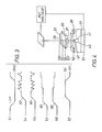
- FIG. 4 shows in exploded view the various anodes with the insulative material omitted. Also, the target is shown but the evacuated housing has been omitted for sake of clarity.
- the beam shaping layers are represented by rings or bars with conductor paths 51 to 58.
- the terminal 51 connects to the emitter 40.
- the magnet layer 29 connects to a selected voltage source.
- the anode 26 connects to the terminal 52.
- the anode 26 is positive, slightly less than 5 V (volts) to initiate current emission.
- the wave form 51 is switched to ground while the wave form 52 is switched to approximately 5 volts positive to initiate emission.
- the other deflection plates 21 receive the potentials 53 and 58 stepped up by a bias and switched to opposite steps.
- the step up in the wave forms 53, 54, 55 and 58 forms an aperture lense focusing voltage, narrowing the beam.
- the various wave forms applied to the opposing focus electrodes are mirror images; this jointly deflects the beam in a controlled fashion and also narrows the beam.
- Focus , shaping and deflection are obtained by the step biases 60 applied to the wave forms 53, 54, 55 and 58.
- Beam modulation can be obtained by driving the anode 26 to cutoff, or to intermediate values to control the beam intensity.
- Beam focus or spot size is adjusted by the voltage applied to the layer 16. All the voltage wave forms shown in Fig. 3 can be obtained through MOS or bipolar integrated circuits fabricated on a sideboard location.
- the control voltages applied to the deflector bars are in the millivolt range obtained by sideboard located integrated circuits.
Landscapes
- Cold Cathode And The Manufacture (AREA)
- Powder Metallurgy (AREA)
Claims (10)
- Feldemissionsvorrichtung, umfassend ein leitendes und tragendes Substrat (31), ein Cermet aus isolierenden (44) und leitenden (43) Teilchen, die eine pyramidenförmige oder kegelförmige Gestalt bilden, die sich zu einem spitzen in einer umgebenden Öffnung zentrierten Bereich erstreckt, ein Potential (52) ist angeordnet, um auf den spitzen Bereich so einzuwirken, daß Elektronen veranlaßt werden, von isolierenden Teilchen (44) des spitzen Bereichs (42) zu fließen, um einen Emissionsstrom zu bilden, und ohmscher Kontakt besteht zwischen den isolierenden und leitenden Teilchen, dadurch gekennzeichnet, daß eine Barriere gegen Emission das Leitungsband des Materials der isolierenden Teilchen ist, von welchem Material die Leitungsbandhöhe geringer als etwa 1eV ist.
- Vorrichtung nach Anspruch 1, In der Elektronen in den isolierenden Teilchen (44) mindestens die Energie der Fermikante des leitenden Materials besitzen.
- Vorrichtung nach Anspruch 1 oder 2, in der das Emissionsfeld ausreichend ist um zu veranlassen, daß Elektronenhaftstellen in den isolierenden Teilchen (44) überfüllt sind, und alle Elektronen in dem Leitungsband aus isolierendem Material fließen.
- Feldemissionsvorrichtrung nach einem der Ansprüche 1 bis 3, in der das Cermet (43, 44) gebildet ist auf und leitend verbunden ist an einem Sockel (41) der spitzen Struktur mit dem leitenden Substrat (31).
- Vorrichtung nach einem der Ansprüche 1 bis 4, in der das leitende Material der Teilchen (43) feuerfestes Metall, Nickel, Silber, Aluminium, Boride seltener Erden, hochdotiertes Silizium oder eine Siliziumverbindung feuerfesten Metalls mit einer geringeren Arbeitsfunktion als die den isolierenden Materials ist.
- Vorrichtung nach einem der Ansprüche 1 bis 5, in der die leitenden Teilchen (43) aus Trichromsilicid sind und das isolierende Material Al₂O₃, BeO, B₂O₃, BN, CaO, MgO, SiO₂ oder Si₃N₄ ist.
- Vorrichtung nach einem der Ansprüche 1 bis 6, in der das das Feld für die Emission erzeugende Potential geringer ist als das Ionisationspotential von Restgasen oder -dämpfen innerhalb oder diffundierend innerhalb des Feldes, um die Integrität der emittierenden isolierenden Teilchen zu erhalten, Geräusch und Herabsetzung emittierten Stroms zu verringern und den Betrieb in Gegenwart von Dämpfen und Gasen in dem Feld zu ermöglichen.
- Vorrichtung nach einem der Ansprüche 1 bis 7, enthaltend zwei Paar von Deflektionsstäben (20, 21), die rechtwinklig zueinander und isoliert voneinander sind, wobei die Stäbe relativ zu dem Emissionspunkt (42) zentriert sind; Spannungsmittel, angeschlossen an ein Deflektionspaar; getrennte Spannungsmittel, angeschlossen an das andere Deflektionspaar; und worin die Deflektionsstäbe zur Ablenkung der emittierten Elektronen und zur Fokussierung der emittierten Elektronen wirksam sind.
- Eine Mehrzahl von Feldemissionsvorrichtungen nach einem der Ansprüche 1 bis 7, die sich ein gemeinsamen Substrat (28) teilen, jede auf einen zugeordneten Bereich eines entsprechenden Ziels gerichtet, und integrierte Schaltungssteuerungsmittel einschließend, die integrierend durch das gemeinsame Substrat getragen sind für die Mehrzahl der Feldemissionsvorrichtungen.
- Vorrichtung nach einem der Ansprüche 1 bis 8, gebildet aus Trichromsilicid-Teilchen in ohmschem Kontakt mit Silika- oder Beryllerde-Teilchen.
Priority Applications (4)
| Application Number | Priority Date | Filing Date | Title |
|---|---|---|---|
| US06/798,587 US4663559A (en) | 1982-09-17 | 1985-11-15 | Field emission device |
| AT87303550T ATE81565T1 (de) | 1987-04-22 | 1987-04-22 | Feldemissionsvorrichtung. |
| DE8787303550T DE3782247D1 (de) | 1987-04-22 | 1987-04-22 | Feldemissionsvorrichtung. |
| EP87303550A EP0288616B1 (de) | 1987-04-22 | 1987-04-22 | Feldemissionsvorrichtung |
Applications Claiming Priority (1)
| Application Number | Priority Date | Filing Date | Title |
|---|---|---|---|
| EP87303550A EP0288616B1 (de) | 1987-04-22 | 1987-04-22 | Feldemissionsvorrichtung |
Publications (2)
| Publication Number | Publication Date |
|---|---|
| EP0288616A1 EP0288616A1 (de) | 1988-11-02 |
| EP0288616B1 true EP0288616B1 (de) | 1992-10-14 |
Family
ID=8197873
Family Applications (1)
| Application Number | Title | Priority Date | Filing Date |
|---|---|---|---|
| EP87303550A Expired EP0288616B1 (de) | 1982-09-17 | 1987-04-22 | Feldemissionsvorrichtung |
Country Status (3)
| Country | Link |
|---|---|
| EP (1) | EP0288616B1 (de) |
| AT (1) | ATE81565T1 (de) |
| DE (1) | DE3782247D1 (de) |
Families Citing this family (4)
| Publication number | Priority date | Publication date | Assignee | Title |
|---|---|---|---|---|
| US5332627A (en) * | 1990-10-30 | 1994-07-26 | Sony Corporation | Field emission type emitter and a method of manufacturing thereof |
| CA2227322A1 (en) * | 1995-08-04 | 1997-02-20 | Printable Field Emitters Limited | Field electron emission materials and devices |
| EP0827176A3 (de) * | 1996-08-16 | 2000-03-08 | Tektronix, Inc. | Zerstäubungsfeste, leitende Überzüge mit verbesserter Elektronenemittierung für Kathodenelektroden in Gleichstromplasma-Adressierungsvorrichtungen |
| US6914372B1 (en) * | 1999-10-12 | 2005-07-05 | Matsushita Electric Industrial Co., Ltd. | Electron-emitting element and electron source, field emission image display device, and fluorescent lamp utilizing the same and methods of fabricating the same |
Family Cites Families (5)
| Publication number | Priority date | Publication date | Assignee | Title |
|---|---|---|---|---|
| GB1226627A (de) * | 1967-08-02 | 1971-03-31 | ||
| JPS5436828B2 (de) * | 1974-08-16 | 1979-11-12 | ||
| US4213192A (en) | 1979-01-15 | 1980-07-15 | Christensen Alton O Sr | Electron beam accessed read-write-erase random access memory |
| US4663559A (en) * | 1982-09-17 | 1987-05-05 | Christensen Alton O | Field emission device |
| US4498952A (en) | 1982-09-17 | 1985-02-12 | Condesin, Inc. | Batch fabrication procedure for manufacture of arrays of field emitted electron beams with integral self-aligned optical lense in microguns |
-
1987
- 1987-04-22 AT AT87303550T patent/ATE81565T1/de not_active IP Right Cessation
- 1987-04-22 EP EP87303550A patent/EP0288616B1/de not_active Expired
- 1987-04-22 DE DE8787303550T patent/DE3782247D1/de not_active Expired - Lifetime
Also Published As
| Publication number | Publication date |
|---|---|
| ATE81565T1 (de) | 1992-10-15 |
| DE3782247D1 (de) | 1992-11-19 |
| EP0288616A1 (de) | 1988-11-02 |
Similar Documents
| Publication | Publication Date | Title |
|---|---|---|
| US4663559A (en) | Field emission device | |
| US5030895A (en) | Field emitter array comparator | |
| US4682074A (en) | Electron-beam device and semiconductor device for use in such an electron-beam device | |
| US5606215A (en) | Field emission device arc-suppressor | |
| US12588132B2 (en) | X-ray source with multiple grids | |
| US5734223A (en) | Field emission cold cathode having micro electrodes of different electron emission characteristics | |
| JP3359677B2 (ja) | 荷電粒子ビームの形状制御を可能とする装置 | |
| US5920151A (en) | Structure and fabrication of electron-emitting device having focus coating contacted through underlying access conductor | |
| US5656883A (en) | Field emission devices with improved field emission surfaces | |
| GB2374979A (en) | A field ionisation source | |
| US8450917B2 (en) | High-definition cathode ray tube and electron gun | |
| US5786657A (en) | Field emission electron gun capable of minimizing nonuniform influence of surrounding electric potential condition on electrons emitted from emitters | |
| US5440579A (en) | Compact electron gun having a microdot electron source and a semiconductor laser using said gun for electronic pumping | |
| US5977696A (en) | Field emission electron gun capable of minimizing nonuniform influence of surrounding electric potential condition on electrons emitted from emitters | |
| EP0288616A1 (de) | Feldemissionsvorrichtung | |
| JP2809078B2 (ja) | 電界放出冷陰極およびその製造方法 | |
| KR20020038696A (ko) | 컴팩트한 전계 방출 전자총 및 집속 렌즈 | |
| US6024618A (en) | Method of operating electron tube | |
| US6013974A (en) | Electron-emitting device having focus coating that extends partway into focus openings | |
| US4122369A (en) | Magnetic deflection apparatus positioned behind target | |
| US5723954A (en) | Pulsed hybrid field emitter | |
| JPS63274043A (ja) | 電界放射電子銃 | |
| US4196373A (en) | Electron optics apparatus | |
| US6144145A (en) | High performance field emitter and method of producing the same | |
| KR100421750B1 (ko) | 전자집속시스템 및 그것의 제조방법, 그리고 상기 전자집속시스템을 채용한 전자방출 디바이스 |
Legal Events
| Date | Code | Title | Description |
|---|---|---|---|
| PUAI | Public reference made under article 153(3) epc to a published international application that has entered the european phase |
Free format text: ORIGINAL CODE: 0009012 |
|
| AK | Designated contracting states |
Kind code of ref document: A1 Designated state(s): AT BE CH DE FR GB IT LI NL SE |
|
| 17P | Request for examination filed |
Effective date: 19890625 |
|
| 17Q | First examination report despatched |
Effective date: 19910131 |
|
| RAP3 | Party data changed (applicant data changed or rights of an application transferred) |
Owner name: CHRISTENSEN, ALTON OWEN |
|
| GRAA | (expected) grant |
Free format text: ORIGINAL CODE: 0009210 |
|
| AK | Designated contracting states |
Kind code of ref document: B1 Designated state(s): AT BE CH DE FR GB IT LI NL SE |
|
| PG25 | Lapsed in a contracting state [announced via postgrant information from national office to epo] |
Ref country code: SE Effective date: 19921014 Ref country code: NL Effective date: 19921014 Ref country code: BE Effective date: 19921014 Ref country code: DE Effective date: 19921014 Ref country code: AT Effective date: 19921014 Ref country code: IT Free format text: LAPSE BECAUSE OF FAILURE TO SUBMIT A TRANSLATION OF THE DESCRIPTION OR TO PAY THE FEE WITHIN THE PRESCRIBED TIME-LIMIT;WARNING: LAPSES OF ITALIAN PATENTS WITH EFFECTIVE DATE BEFORE 2007 MAY HAVE OCCURRED AT ANY TIME BEFORE 2007. THE CORRECT EFFECTIVE DATE MAY BE DIFFERENT FROM THE ONE RECORDED. Effective date: 19921014 |
|
| REF | Corresponds to: |
Ref document number: 81565 Country of ref document: AT Date of ref document: 19921015 Kind code of ref document: T |
|
| REF | Corresponds to: |
Ref document number: 3782247 Country of ref document: DE Date of ref document: 19921119 |
|
| ET | Fr: translation filed | ||
| NLV1 | Nl: lapsed or annulled due to failure to fulfill the requirements of art. 29p and 29m of the patents act | ||
| PLBE | No opposition filed within time limit |
Free format text: ORIGINAL CODE: 0009261 |
|
| STAA | Information on the status of an ep patent application or granted ep patent |
Free format text: STATUS: NO OPPOSITION FILED WITHIN TIME LIMIT |
|
| 26N | No opposition filed | ||
| PGFP | Annual fee paid to national office [announced via postgrant information from national office to epo] |
Ref country code: CH Payment date: 19950425 Year of fee payment: 9 |
|
| PG25 | Lapsed in a contracting state [announced via postgrant information from national office to epo] |
Ref country code: LI Effective date: 19960430 Ref country code: CH Effective date: 19960430 |
|
| REG | Reference to a national code |
Ref country code: CH Ref legal event code: PL |
|
| PGFP | Annual fee paid to national office [announced via postgrant information from national office to epo] |
Ref country code: GB Payment date: 19980415 Year of fee payment: 12 |
|
| PGFP | Annual fee paid to national office [announced via postgrant information from national office to epo] |
Ref country code: FR Payment date: 19980427 Year of fee payment: 12 |
|
| PG25 | Lapsed in a contracting state [announced via postgrant information from national office to epo] |
Ref country code: GB Free format text: LAPSE BECAUSE OF NON-PAYMENT OF DUE FEES Effective date: 19990422 |
|
| GBPC | Gb: european patent ceased through non-payment of renewal fee |
Effective date: 19990422 |
|
| PG25 | Lapsed in a contracting state [announced via postgrant information from national office to epo] |
Ref country code: FR Free format text: LAPSE BECAUSE OF NON-PAYMENT OF DUE FEES Effective date: 19991231 |
|
| REG | Reference to a national code |
Ref country code: FR Ref legal event code: ST |