EP0288079A2 - Flexible container with closing means - Google Patents
Flexible container with closing means Download PDFInfo
- Publication number
- EP0288079A2 EP0288079A2 EP88106510A EP88106510A EP0288079A2 EP 0288079 A2 EP0288079 A2 EP 0288079A2 EP 88106510 A EP88106510 A EP 88106510A EP 88106510 A EP88106510 A EP 88106510A EP 0288079 A2 EP0288079 A2 EP 0288079A2
- Authority
- EP
- European Patent Office
- Prior art keywords
- liner
- side wall
- wall structure
- opening
- piece
- Prior art date
- Legal status (The legal status is an assumption and is not a legal conclusion. Google has not performed a legal analysis and makes no representation as to the accuracy of the status listed.)
- Ceased
Links
Images


Classifications
-
- B—PERFORMING OPERATIONS; TRANSPORTING
- B65—CONVEYING; PACKING; STORING; HANDLING THIN OR FILAMENTARY MATERIAL
- B65D—CONTAINERS FOR STORAGE OR TRANSPORT OF ARTICLES OR MATERIALS, e.g. BAGS, BARRELS, BOTTLES, BOXES, CANS, CARTONS, CRATES, DRUMS, JARS, TANKS, HOPPERS, FORWARDING CONTAINERS; ACCESSORIES, CLOSURES, OR FITTINGS THEREFOR; PACKAGING ELEMENTS; PACKAGES
- B65D88/00—Large containers
- B65D88/16—Large containers flexible
- B65D88/1612—Flexible intermediate bulk containers [FIBC]
- B65D88/1618—Flexible intermediate bulk containers [FIBC] double-walled or with linings
-
- B—PERFORMING OPERATIONS; TRANSPORTING
- B65—CONVEYING; PACKING; STORING; HANDLING THIN OR FILAMENTARY MATERIAL
- B65D—CONTAINERS FOR STORAGE OR TRANSPORT OF ARTICLES OR MATERIALS, e.g. BAGS, BARRELS, BOTTLES, BOXES, CANS, CARTONS, CRATES, DRUMS, JARS, TANKS, HOPPERS, FORWARDING CONTAINERS; ACCESSORIES, CLOSURES, OR FITTINGS THEREFOR; PACKAGING ELEMENTS; PACKAGES
- B65D88/00—Large containers
- B65D88/16—Large containers flexible
- B65D88/1612—Flexible intermediate bulk containers [FIBC]
- B65D88/1675—Lifting fittings
- B65D88/1681—Flexible, e.g. loops, or reinforcements therefor
Definitions
- This invention relates to intermediate bulk containers used in the storage and transport of bulk materials in granular, powder or paste forms.
- Said container comprising at least one lifting loop, a side wall structure formed from at least one piece of flexible woven fabric and a base structure and a liner of impervious material.
- Such containers are generally manufactured from at least one piece of woven fabric, particularly woven poly- propylene or other suitable synthetic material and required to carry loads of 500 kgs or more with a considerable safety margin.
- Typical common features are: - a side wall structure, made together from one or more panels of woven fabric stitched up to form a tube or from a piece of tubular fabric eliminating side seams. - a base construction closing the lower open end of the side wall structure.
- lifting mean(s) at the upper end of the side wall structure capable of taking the load when the lifting mean(s) are engaged with suitable lifting mechanisms like hooks or tines of a fork lift truck.
- the lid can be equipped with a filling spout of flexible material.
- Liners are generally in the form of a cylindrical length of polyethylene or other impermeable plastics material. At the discharge end of the container the liner is either closed by welding and laid loosely within the side wall structure and/or closed together with discharge spout in the base construction.
- the liner is either fully open or prewelded to form a restricted fill opening and this end of the liner may be brought through a filling opening in the outer container and may be sealed by welding, tying off etc. after the container has been filled.
- a second problem with improved air tight liners is the bursting of the liners when stacked. It is especially the liners at the bottom of the stack which are prone to bursting and at times causing larger parts of a stack to collapse.
- flexible containers are stacked up to 12 tiers high and all really airthight liners in the bottom tiers will burst.
- Burst liners have a secondary adverse effect as they offer no protection against contamination when they are stored outside.
- Singel point lift containers are especially elastic and vertical deformations of 5 - 15 cm are normal under the combined static and dynamic loads during handling . If the top of the liner is fastened to the top of such containers the liner can easily be torn apart due to these deformations. It is obviously then a better solution to leave the liner top loosely laid inside the top of the container and secure it immediately before discharge.
- the invention according to the applicants EPO-patent application no 87100142.6 permits both entrapped air to escape when stacked and prevents the liner to block the discharge opening.
- the manufacture of such liner, with overlapping sidewelds forming ducts to deaerate entrapped air and side skirts fastened to the side seams in the wall structure is, however, complicated and expensive.
- the liner must be placed inside the wall structure prior to stitching the side wall seams and care must be taken to avoid those parts of the liner which are inside the side welds to get into the seams.
- the main object of the present invention is to provide inexpensive means to deaerate entrapped air in liners used in flexible intermediate bulk containers of various designs and thereby permit stable stacking in a multitude of tiers.
- An other object was to find means of fastening the liner to the outer container to prevent the liner from being pulled down by the product and block the discharge opening when the containers are emptied.
- An object was also to design said fastening means in such way that no stress was transferred from the outer envelope to the liner during normal handling of the containers.
- a further object was to develop means to prevent damage of liners when the lifting loop(s) of open top containers are engaged by suitable lifting mechanisms, e.g. the tines of fork lift truck, hooks etc.
- the tube was joined to the wall structure with seams and the top of the liner pulled out through this tube.
- the liner opening and the free end of the tube was then tied off with string.
- the folds then forms ducts permitting air to escape but prevents contamination of the product inside the container.
- the side seam is interrupted level with the fill height and both the protective piece of material, preferably in the form of a tube, and the string are joined to the side wall structure in connection with the side seam.
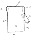
- Fig. l shows a flat piece of flexible woven material 1 which has been folded along its transverse centerline and joined along the edges with seams 2 and 3 to form a tube with a closed upper end forming a lifting loop 4 and an open lower end which can be closed with a suitable base structure in a known way.
- the seam 2 is stopped some distance from the top of the lifting loop to form an opening 5 for the insertion of suitable lifting mechanisms.
- the seam 3 joining the other two edges is stopped at a larger distance from the top of the lifting loops 4, positioning the end of the seam 3 at what will later be the filling level when the container is filled, forming a larger opening 6.
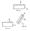
- the piece of flexible material 7 in Fig. 2a is folded along its center into a u-shape and inserted into the opening 6 at an angle with the free edges 8 resting at the top of the seam 3.
- the piece 7 is then joined to the piece 1 with the connecting seam 9 as shown in Fig. 3.
- This seam 9 starts at approximately the same distance from the top of the lifting loop 4 as the seam 2 and joins the edges of the piece 1 changing the opening 6 into 6 ⁇ of approximately the same size as the opening 5.
- the seam 9 in Fig. 3 is then continued at an angle closing the upper end of the piece 7 leaving an opening 11 in the side wall structure between the seams 3 and 9 through which one can pull out the top of the liner 13.
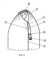
- Fig. 4 the top of the liner 13 is shown when folded and pressed together and the piece 7 wrapped around and tied off with the string 10 connecting both to the outside of the side wall structure.
- the string 10 has been fastened to the side wall for example with the joining seam 3 as shown in fig. 3.
- the top of the container in Fig. 4 has been completed with a protective sleeve 12 preforming the lifting loop 4 clearly defining the openings 5 and 6 ⁇ used when the lifting loop is engaged by suitable lifting equipment.
- the protective piece of material 7 used to protect the liner outside the side wall structure can have several forms. It can be made from tubular fabric or stitched toghether to form a tube or parts of a tube as indicated in Fig. 2c and it may have an upper closed end. Further it may be joined to the side wall structure by other suitable means, e.g. glue, hotmelt etc.
- FIG. 5 A preferred alternative arrangement is shown in Fig. 5.
- a longitudinal slit 16 equivalent to the gap 11 between the two seams 3 and 9 in Fig. 3 is cut in the side wall structure in the vicinity of the material fill height.
- the piece of material 7 now folded to form a "C" as shown in Fig. 2b is then joined to the side wall structure, its two edges 8 forming a longitudinal opening 15 is lined up with the slit 16, with suitable fastening means, e.g. the transverse seam 14 in Fig. 5 closing its upper open end at the same time.
- a slit of about the same size as the slit 16 in the side wall structure must be cut in its wall and both slits lined up before the piece of material 7 is joined the side wall structure.
- the piece of material 7 of Fig. 2c, but now folded as 7 in Fig. 2b can be pulled through the slit 16 and joined to the inside of the side wall structure.
- the string 10 is fastened to the side wall below the slit 16.
- the top of the liner 13 is pulled out through the slit 16 in Fig. 5 into the protective piece of material 7, then folded or pressed together and the piece 7 wrapped around and tied off with the string 10 connecting both to the outside of the side wall structure.
- modified containers can be stably stacked in a multitude of tiers, which is an essential feature for preventing accidents. As entrapped air can escape, the liners will not burst when stacked.
- Another advantage of the present invention is that the top of the liner is positively removed from the openings of the lifting loop(s) and are less liable to damage when these are engaged by the lifting mechanisms.
- An essential advantage which is obtained by the present invention is that the liner is secured to the side wall structure without transferring stress from the side wall to the liner. This fastening of the liner to the outer container will simplify discharge operations eliminating the need to secure the liner before the containers are discharged and the liners will no longer block the discharge opening.
Landscapes
- Engineering & Computer Science (AREA)
- Mechanical Engineering (AREA)
- Packages (AREA)
- Supplying Of Containers To The Packaging Station (AREA)
Abstract
Description
- This invention relates to intermediate bulk containers used in the storage and transport of bulk materials in granular, powder or paste forms. Said container comprising at least one lifting loop, a side wall structure formed from at least one piece of flexible woven fabric and a base structure and a liner of impervious material.
- Such containers are generally manufactured from at least one piece of woven fabric, particularly woven poly- propylene or other suitable synthetic material and required to carry loads of 500 kgs or more with a considerable safety margin.
- Several proposals for the construction of such containers are known. Typical common features are:
- a side wall structure, made together from one or more panels of woven fabric stitched up to form a tube or from a piece of tubular fabric eliminating side seams.
- a base construction closing the lower open end of the side wall structure.
- lifting mean(s) at the upper end of the side wall structure capable of taking the load when the lifting mean(s) are engaged with suitable lifting mechanisms like hooks or tines of a fork lift truck.
- and frequently closing means at the upper end of the side wall structure in the form of a lid of flexible material, stitched to the upper circumference of the wall structure. The lid can be equipped with a filling spout of flexible material.
- an impervious inner envelope or liner within the outer envelope to protect the contents from contamination, e.g. water intrusion, dust etc. - Liners are generally in the form of a cylindrical length of polyethylene or other impermeable plastics material. At the discharge end of the container the liner is either closed by welding and laid loosely within the side wall structure and/or closed together with discharge spout in the base construction.
- At the filling end the liner is either fully open or prewelded to form a restricted fill opening and this end of the liner may be brought through a filling opening in the outer container and may be sealed by welding, tying off etc. after the container has been filled.
- In recent years extrusion techniques (coextrucion) and polymeres (LLDPE) have improved. Todays liners are therefore for practical purposes completely without micro-holes which, toghether with improved methods for closing the liners, causes severe problems during handling and transport of bulk materials in intermediate bulk container:
- As bulk materials are filled into flexible containers the material will be "loose", i.e. will contain smaller or larger quantities of entrapped air which fills up the space between the granules. Intermediate bulk containers are just as often as not stored outside and normal practice -s to close the liners before the containers leave the packing station. During the subsequent handling the material is compressed and entrapped air escapes to the top.
- When the containers are stacked for storage or transport, the material in the containers are further compressed and thereby even more air are released. The result is the formation of an air cushion inside the airtight liner. The container on top will "float" on the air cushion in the container below, thus causing the complete stack of containers to become unstable. For maximum utilization of storage area it is normal practice to stack such containers up to five tiers high. Instability in the stacks due to these air cushions creates dangerous situations as containers at the top tiers easely topple.
- A second problem with improved air tight liners is the bursting of the liners when stacked. It is especially the liners at the bottom of the stack which are prone to bursting and at times causing larger parts of a stack to collapse. When loaded in ships holds, flexible containers are stacked up to 12 tiers high and all really airthight liners in the bottom tiers will burst.
- Burst liners have a secondary adverse effect as they offer no protection against contamination when they are stored outside.
- To avoid the formation of air cushions inside liners in intermediate bulk containers, the inventors have tried out several alternative solutions:
- to evacuate entrapped air at the filling station before closing the liner. Unfortunately too large quantities of air was still released when the material was compressed during subsequent handling and stacking.
- to compress the material by vibration at the filling station. This method worked well for some products especially when combined the evacuation of released air before closing the liner. However, the necessary equipment is expensive and each product has its own distinct vibration frequency to compress it, wrong choice of frequency actually leads to aeration of the product, especially fine powders, which often have to be fluidized when filled in containers. - Another problem connected with the use of liners occurs when the containers are emptied. When the container's contents is discharged the product inside it will form a funnel. If the top of the liner is laid loosely on top of the product, the liner will be pulled down by the product into the funnel and block the discharge opening. To avoid this problem during discharge the top of the liners are often secured to the top of the containers at the same time as the filling opening is closed or at least just before the container shall be emptied.
- Singel point lift containers are especially elastic and vertical deformations of 5 - 15 cm are normal under the combined static and dynamic loads during handling . If the top of the liner is fastened to the top of such containers the liner can easily be torn apart due to these deformations. It is obviously then a better solution to leave the liner top loosely laid inside the top of the container and secure it immediately before discharge.
- However, on all types of containers without a closing lid at the top, both alternatives have the disadvantage that the top of the liners often will be damaged by the lifting mechanisms when these are inserted into the lifting loop(s).
- The invention according to the applicants EPO-patent application no 87100142.6 permits both entrapped air to escape when stacked and prevents the liner to block the discharge opening. The manufacture of such liner, with overlapping sidewelds forming ducts to deaerate entrapped air and side skirts fastened to the side seams in the wall structure is, however, complicated and expensive. The liner must be placed inside the wall structure prior to stitching the side wall seams and care must be taken to avoid those parts of the liner which are inside the side welds to get into the seams.
- The above sited patent application neither solves the problem of possible liner damage by the lifting tools nor is applicable for containers without side seams in the wall structure and in addition represents an expensive solution. The application of such containers has therefore been limited.
- The main object of the present invention is to provide inexpensive means to deaerate entrapped air in liners used in flexible intermediate bulk containers of various designs and thereby permit stable stacking in a multitude of tiers.
- An other object was to find means of fastening the liner to the outer container to prevent the liner from being pulled down by the product and block the discharge opening when the containers are emptied.
- An object was also to design said fastening means in such way that no stress was transferred from the outer envelope to the liner during normal handling of the containers.
- A further object was to develop means to prevent damage of liners when the lifting loop(s) of open top containers are engaged by suitable lifting mechanisms, e.g. the tines of fork lift truck, hooks etc.
- As earlier solutions developing elaborate liner designs have had limited success, the inventors decided to base their solutions on the use of the present liner designs and to develop modifications to the various designs of side wall structures to achieve their object.
- In a first trial the inventors simply pushed the top of the liner with the filling opening down between the liner and the side wall structure. The product itself closed the filling opening due to the pressure it excerted on the side walls, however entrapped air was permitted to escape during stacking due to the overpressure inside the liner. This simple sealing arrangement worked extremely well.
- A test showed that the contents in six containers filled with Portland cement had virgin quality after more than two years outdoor, uncovered storage in the South of Norway.
- Where as it was easy to position the liner opening when the container was filled with fluidized materials, this job was rather cumbersome with granular products. But the liner top worked its way up to the top of the container during handling, finally exposing the fill opening.
- The inventors now looked for a solution to secure the liner top in fixed position. A task which proved unsuccessful until they stumbled on the idea to pull the liner out through a longitudinal slit in the container wall but below the fill height of the contents. Adding a tube made of the same material as the outer envelope secured ample protection for the part of the liner outside the wall structure against damage during handling.
- The tube was joined to the wall structure with seams and the top of the liner pulled out through this tube. The liner opening and the free end of the tube was then tied off with string. The folds then forms ducts permitting air to escape but prevents contamination of the product inside the container.
- As it was rather troublesome to pull the liner out through the tube when the container was filled with granular products the slit with the protruding tube was raised to level with the fill height.
- To avoid the tube to cause disturbances in handling, its end needed to be fastened to the side wall, e.g. with glue. The simpler method, however, was to join the string used for tying off tube and liner to the side wall structure some distance below the slit.
- This solution proved successful as the slit, level with the fill height, did not tear due to lack of hoop stress in this area, even when stacked. The liner folded itself nicely over the contents away from the lifting loops when the top was pulled out through the tube. As the liner can move in the slit through the side wall no stress is transferred to the liner during handling. As the liner top was kept level with the fill height during discharge, the liner will not be pulled down and block the discharge opening when the container is emptied.
- In an other preferred arrangement the side seam is interrupted level with the fill height and both the protective piece of material, preferably in the form of a tube, and the string are joined to the side wall structure in connection with the side seam.
- The scope and characterizing features of the invention are as defined in the attached claims.
- In order that the invention may be better understood the manufacture of the arrangement will be described in more detail, by the way of example only, with reference to the accompanying drawings.
- Fig. 1 shows the top of a container with integral lifting loop and with the protective piece of material shown in fig. 2a inserted.
- Fig. 2a+b shows two preferred folding arrangements of the protective piece of material.
- Fig. 2c shows an alternative arrangement of the protective piece of material.
- Fig. 3 shows a completed arrangement of fig. 1.
- Fig. 4 shows a perspective view of a filled container with integral lifting loop and liner which has been closed in accordance with the invention.
- Fig. 5 shows a perspective view of a filled open top container with four lifting loops and liner closed in accordance with the invention.
- Fig. l shows a flat piece of flexible
woven material 1 which has been folded along its transverse centerline and joined along the edges withseams lifting loop 4 and an open lower end which can be closed with a suitable base structure in a known way. - The
seam 2 is stopped some distance from the top of the lifting loop to form anopening 5 for the insertion of suitable lifting mechanisms. Theseam 3 joining the other two edges is stopped at a larger distance from the top of the liftingloops 4, positioning the end of theseam 3 at what will later be the filling level when the container is filled, forming alarger opening 6. - The piece of
flexible material 7 in Fig. 2a is folded along its center into a u-shape and inserted into theopening 6 at an angle with thefree edges 8 resting at the top of theseam 3. Thepiece 7 is then joined to thepiece 1 with the connectingseam 9 as shown in Fig. 3. Thisseam 9 starts at approximately the same distance from the top of thelifting loop 4 as theseam 2 and joins the edges of thepiece 1 changing theopening 6 into 6ʹ of approximately the same size as theopening 5. Theseam 9 in Fig. 3 is then continued at an angle closing the upper end of thepiece 7 leaving anopening 11 in the side wall structure between theseams liner 13. - In Fig. 4 the top of the
liner 13 is shown when folded and pressed together and thepiece 7 wrapped around and tied off with thestring 10 connecting both to the outside of the side wall structure. Thestring 10 has been fastened to the side wall for example with the joiningseam 3 as shown in fig. 3. - The top of the container in Fig. 4 has been completed with a
protective sleeve 12 preforming thelifting loop 4 clearly defining theopenings 5 and 6ʹ used when the lifting loop is engaged by suitable lifting equipment. - The protective piece of
material 7 used to protect the liner outside the side wall structure can have several forms. It can be made from tubular fabric or stitched toghether to form a tube or parts of a tube as indicated in Fig. 2c and it may have an upper closed end. Further it may be joined to the side wall structure by other suitable means, e.g. glue, hotmelt etc. - In the above example the arrangement according to the invention has been fitted to the side wall structure in connection with a side seam in same, but it will be appreciated that the invention can be applied anywhere in the side wall structure at the approximate level of the material fill height.
- A preferred alternative arrangement is shown in Fig. 5. A
longitudinal slit 16 equivalent to thegap 11 between the twoseams material 7 now folded to form a "C" as shown in Fig. 2b is then joined to the side wall structure, its twoedges 8 forming alongitudinal opening 15 is lined up with theslit 16, with suitable fastening means, e.g. the transverse seam 14 in Fig. 5 closing its upper open end at the same time. - If the piece of
material 7 is tubular, a slit of about the same size as theslit 16 in the side wall structure must be cut in its wall and both slits lined up before the piece ofmaterial 7 is joined the side wall structure. - Alternatively the piece of
material 7 of Fig. 2c, but now folded as 7 in Fig. 2b can be pulled through theslit 16 and joined to the inside of the side wall structure. - The
string 10 is fastened to the side wall below theslit 16. - To close the container the top of the
liner 13 is pulled out through theslit 16 in Fig. 5 into the protective piece ofmaterial 7, then folded or pressed together and thepiece 7 wrapped around and tied off with thestring 10 connecting both to the outside of the side wall structure. - By the present invention one has obtained an inexpensive way to dearate entrapped air of flexible intermediate bulk containers of various designs and comprising a liner of impervious material. Accordingly the formation of air cushions inside such liners are prevented. This invention permits the use of present liner designs and does not influence the filling operation of the containers. The closing of the liners has been simplified as the operator only has to pull the top of the liner with the filling opening out through the side wall structure and tie it off together with its protective means.
- Thus the contents will be protected against contamination but will still permit air to escape through the closure. Such modified containers can be stably stacked in a multitude of tiers, which is an essential feature for preventing accidents. As entrapped air can escape, the liners will not burst when stacked.
- Another advantage of the present invention is that the top of the liner is positively removed from the openings of the lifting loop(s) and are less liable to damage when these are engaged by the lifting mechanisms.
- An essential advantage which is obtained by the present invention is that the liner is secured to the side wall structure without transferring stress from the side wall to the liner. This fastening of the liner to the outer container will simplify discharge operations eliminating the need to secure the liner before the containers are discharged and the liners will no longer block the discharge opening.
Claims (4)
characterized in that the side wall structure has an opening (11,16) approximately at the level of the material fill height and said opening (11,16) being covered by a piece of flexible material (7) of suitable shape and that said piece of material (7) is fastened to the side wall structure or that said piece (7) is inserted in said opening (11,16) and fastened to the inside or outside of the side wall structure such that the top of the liner (13) can be pulled out through the opening (11,16) and be protected by said piece of material (7).
characterized in that the piece of material (7) at least along a part of its length has tube form.
characterized in that the piece of material (7) is folded to form a "U" or a "C".
characterized in that liner (13) and protective piece of material (7) can be tied off with fastening means (10) secured to the side wall structure below the opening (11,16).
Applications Claiming Priority (2)
| Application Number | Priority Date | Filing Date | Title |
|---|---|---|---|
| NO871706 | 1987-04-24 | ||
| NO871706A NO161305C (en) | 1987-04-24 | 1987-04-24 | LARGE BAG WITH CLOSING DEVICE. |
Publications (2)
| Publication Number | Publication Date |
|---|---|
| EP0288079A2 true EP0288079A2 (en) | 1988-10-26 |
| EP0288079A3 EP0288079A3 (en) | 1989-08-09 |
Family
ID=19889881
Family Applications (1)
| Application Number | Title | Priority Date | Filing Date |
|---|---|---|---|
| EP88106510A Ceased EP0288079A3 (en) | 1987-04-24 | 1988-04-22 | Flexible container with closing means |
Country Status (5)
| Country | Link |
|---|---|
| EP (1) | EP0288079A3 (en) |
| CN (1) | CN88103207A (en) |
| ES (1) | ES2007478A6 (en) |
| NO (1) | NO161305C (en) |
| PT (1) | PT87325A (en) |
Cited By (3)
| Publication number | Priority date | Publication date | Assignee | Title |
|---|---|---|---|---|
| EP0535869A1 (en) * | 1991-10-03 | 1993-04-07 | Norsk Hydro A/S | Improvements in and relating to flexible containers |
| RU2256593C2 (en) * | 2003-09-23 | 2005-07-20 | ООО "Производственная компания "ХИМПЭК" | Flexible container and method of container production |
| RU200578U1 (en) * | 2019-12-25 | 2020-10-29 | Олег Валерьевич Середенин | Flexible container liner |
Families Citing this family (1)
| Publication number | Priority date | Publication date | Assignee | Title |
|---|---|---|---|---|
| DE102004003364A1 (en) * | 2004-01-22 | 2005-08-11 | Wacker-Chemie Gmbh | Device for transporting highly dispersed powders and process for their filling and emptying |
Family Cites Families (3)
| Publication number | Priority date | Publication date | Assignee | Title |
|---|---|---|---|---|
| FR2450754A3 (en) * | 1979-03-06 | 1980-10-03 | Est Imprimerie Papeterie | Bag with inner plastics lining and stitched outside - has holes for carrying cord and is closed at bottom by gathering and tying |
| DE3539619C1 (en) * | 1985-11-08 | 1987-04-30 | Bayer Ag | Packaging for granular or small-grain products with a high degree of purity, and method for filling, transporting and emptying the packaging |
| GB8603966D0 (en) * | 1986-02-18 | 1986-03-26 | Agripac Dundee Ltd | Industrial containers |
-
1987
- 1987-04-24 NO NO871706A patent/NO161305C/en unknown
-
1988
- 1988-04-22 EP EP88106510A patent/EP0288079A3/en not_active Ceased
- 1988-04-22 ES ES8801249A patent/ES2007478A6/en not_active Expired
- 1988-04-22 PT PT8732588A patent/PT87325A/en not_active Application Discontinuation
- 1988-04-23 CN CN198888103207A patent/CN88103207A/en active Pending
Cited By (6)
| Publication number | Priority date | Publication date | Assignee | Title |
|---|---|---|---|---|
| EP0535869A1 (en) * | 1991-10-03 | 1993-04-07 | Norsk Hydro A/S | Improvements in and relating to flexible containers |
| EP0581393A3 (en) * | 1991-10-03 | 1994-02-09 | Norsk Hydro A/S | Flexible containers |
| US5350239A (en) * | 1991-10-03 | 1994-09-27 | Norsk Hydro A.S. | Suspension and venting |
| TR26231A (en) * | 1991-10-03 | 1995-02-15 | Norsk Hydro As | DEVELOPMENTS IN FLEXIBLE CONTAINERS AND RELATED DEVICES. |
| RU2256593C2 (en) * | 2003-09-23 | 2005-07-20 | ООО "Производственная компания "ХИМПЭК" | Flexible container and method of container production |
| RU200578U1 (en) * | 2019-12-25 | 2020-10-29 | Олег Валерьевич Середенин | Flexible container liner |
Also Published As
| Publication number | Publication date |
|---|---|
| NO871706L (en) | 1988-10-25 |
| PT87325A (en) | 1989-05-12 |
| NO161305C (en) | 1989-08-02 |
| CN88103207A (en) | 1988-12-21 |
| EP0288079A3 (en) | 1989-08-09 |
| NO161305B (en) | 1989-04-24 |
| NO871706D0 (en) | 1987-04-24 |
| ES2007478A6 (en) | 1989-06-16 |
Similar Documents
| Publication | Publication Date | Title |
|---|---|---|
| RU1836262C (en) | Packing for transportation and storage of bulk and liquid cargoes | |
| US4499599A (en) | Stackable flexible bulk container | |
| US4817824A (en) | Collapsible bulk container | |
| US4364424A (en) | End wall closure for bulk material transport bag | |
| US5967579A (en) | Industrial diaper for flexible bulk containers | |
| EP0080839B1 (en) | Intermediate bulk containers | |
| EP0535869B1 (en) | Improvements in and relating to flexible containers | |
| US5865541A (en) | Bulk container liner and method | |
| US20060110074A1 (en) | Bulk bag for meat and meat products | |
| US20010027826A1 (en) | Flexible intermediate bulk container with fork lift guide | |
| US6056440A (en) | Sift proofing membrane for bulk lift bag and method | |
| WO2001025101A1 (en) | Bulk container suitable for dangerous goods | |
| US4953987A (en) | Cone top to flat top fabric transport bag | |
| EP0288079A2 (en) | Flexible container with closing means | |
| EP0118112B1 (en) | Flexible container to be filled with bulk material and method for its manufacture | |
| AU615652B2 (en) | Flexible container comprising several lifting means | |
| GB1581438A (en) | Containers | |
| US4750846A (en) | Container for transport and storage of bulk material | |
| US5536086A (en) | Reinforced wall bottom closure construction for a bulk bag | |
| US4832506A (en) | Flexible container to be filled with bulk material and method for its manufacture | |
| EP0376622B1 (en) | Flexible container | |
| EP0589483A1 (en) | Intermediate bulk container and method of packaging | |
| EP0180379A2 (en) | Intermediate bulk containers | |
| EP0300539A1 (en) | Double-walled bag of high loading capacity | |
| GB2185732A (en) | Container |
Legal Events
| Date | Code | Title | Description |
|---|---|---|---|
| PUAI | Public reference made under article 153(3) epc to a published international application that has entered the european phase |
Free format text: ORIGINAL CODE: 0009012 |
|
| AK | Designated contracting states |
Kind code of ref document: A2 Designated state(s): AT BE DE FR GB NL SE |
|
| PUAL | Search report despatched |
Free format text: ORIGINAL CODE: 0009013 |
|
| RHK1 | Main classification (correction) |
Ipc: B65D 88/16 |
|
| AK | Designated contracting states |
Kind code of ref document: A3 Designated state(s): AT BE DE FR GB NL SE |
|
| 17P | Request for examination filed |
Effective date: 19891107 |
|
| 17Q | First examination report despatched |
Effective date: 19911021 |
|
| STAA | Information on the status of an ep patent application or granted ep patent |
Free format text: STATUS: THE APPLICATION HAS BEEN REFUSED |
|
| 18R | Application refused |
Effective date: 19920416 |