EP0080839B1 - Intermediate bulk containers - Google Patents
Intermediate bulk containers Download PDFInfo
- Publication number
- EP0080839B1 EP0080839B1 EP82306155A EP82306155A EP0080839B1 EP 0080839 B1 EP0080839 B1 EP 0080839B1 EP 82306155 A EP82306155 A EP 82306155A EP 82306155 A EP82306155 A EP 82306155A EP 0080839 B1 EP0080839 B1 EP 0080839B1
- Authority
- EP
- European Patent Office
- Prior art keywords
- hexagon
- parallel
- supporting
- members
- cradle
- Prior art date
- Legal status (The legal status is an assumption and is not a legal conclusion. Google has not performed a legal analysis and makes no representation as to the accuracy of the status listed.)
- Expired
Links
Images


Classifications
-
- B—PERFORMING OPERATIONS; TRANSPORTING
- B65—CONVEYING; PACKING; STORING; HANDLING THIN OR FILAMENTARY MATERIAL
- B65D—CONTAINERS FOR STORAGE OR TRANSPORT OF ARTICLES OR MATERIALS, e.g. BAGS, BARRELS, BOTTLES, BOXES, CANS, CARTONS, CRATES, DRUMS, JARS, TANKS, HOPPERS, FORWARDING CONTAINERS; ACCESSORIES, CLOSURES, OR FITTINGS THEREFOR; PACKAGING ELEMENTS; PACKAGES
- B65D88/00—Large containers
- B65D88/16—Large containers flexible
- B65D88/22—Large containers flexible specially adapted for transport
-
- B—PERFORMING OPERATIONS; TRANSPORTING
- B65—CONVEYING; PACKING; STORING; HANDLING THIN OR FILAMENTARY MATERIAL
- B65D—CONTAINERS FOR STORAGE OR TRANSPORT OF ARTICLES OR MATERIALS, e.g. BAGS, BARRELS, BOTTLES, BOXES, CANS, CARTONS, CRATES, DRUMS, JARS, TANKS, HOPPERS, FORWARDING CONTAINERS; ACCESSORIES, CLOSURES, OR FITTINGS THEREFOR; PACKAGING ELEMENTS; PACKAGES
- B65D88/00—Large containers
- B65D88/16—Large containers flexible
- B65D88/1612—Flexible intermediate bulk containers [FIBC]
- B65D88/1675—Lifting fittings
- B65D88/1681—Flexible, e.g. loops, or reinforcements therefor
- B65D88/1687—Flexible, e.g. loops, or reinforcements therefor specially adapted for the forks of a forklift
-
- B—PERFORMING OPERATIONS; TRANSPORTING
- B65—CONVEYING; PACKING; STORING; HANDLING THIN OR FILAMENTARY MATERIAL
- B65D—CONTAINERS FOR STORAGE OR TRANSPORT OF ARTICLES OR MATERIALS, e.g. BAGS, BARRELS, BOTTLES, BOXES, CANS, CARTONS, CRATES, DRUMS, JARS, TANKS, HOPPERS, FORWARDING CONTAINERS; ACCESSORIES, CLOSURES, OR FITTINGS THEREFOR; PACKAGING ELEMENTS; PACKAGES
- B65D2588/00—Large container
- B65D2588/16—Large container flexible
- B65D2588/162—Flexible intermediate bulk containers [FIBC]
- B65D2588/165—FIBC on a pallet base
-
- Y—GENERAL TAGGING OF NEW TECHNOLOGICAL DEVELOPMENTS; GENERAL TAGGING OF CROSS-SECTIONAL TECHNOLOGIES SPANNING OVER SEVERAL SECTIONS OF THE IPC; TECHNICAL SUBJECTS COVERED BY FORMER USPC CROSS-REFERENCE ART COLLECTIONS [XRACs] AND DIGESTS
- Y10—TECHNICAL SUBJECTS COVERED BY FORMER USPC
- Y10S—TECHNICAL SUBJECTS COVERED BY FORMER USPC CROSS-REFERENCE ART COLLECTIONS [XRACs] AND DIGESTS
- Y10S206/00—Special receptacle or package
- Y10S206/821—Stacking member
Definitions
- This invention relates to flexible intermediate bulk containers, which are hereinafter referred to as IBC's.
- IBC's flexible intermediate bulk containers
- Such containers which are often in the form of bags or sacks fabricated from a woven fabric, e.g. woven from polyolefin fibres or ribbons, often with an impervious liner, e.g, as a separate inner plastics sack or having an inner or outer plastics laminated coating, are widely used for transporting powdery or granular materials, such as chemicals, e.g. fertilizers, when it is desired that a unit package should be of the order of 0.5 to 3 m 3 .
- IBC's have a capacity of 1 to 1.5 m 3 .
- IBC's have been provided with lifting straps or slings sewn or otherwise attached to the container or formed integrally therewith.
- the contents of the IBC When lifted by such means, the contents of the IBC are compressed and tend to give the IBC a convex top. This gives rise to problems when it is desired to stack the IBC's several high since the convex top tends to give rise to stack instability with consequent safety hazards.
- the IBC's are lifted from the top, it is often necessary for an operative to climb on to the top of the stack to attach the slings etc. to the lifting device.
- the IBC's are transported on pallets of the conventional type, generally with one IBC per pallet, so that the palletised IBC can be moved by means of conventional fork-lift trucks as described in "Conserva” 16 (1968), 10, page 250. Formation of a convex top to the IBC, with consequent stacking instability is still liable to occur, particularly where the IBC is lifted by slings etc. on to the pallet.
- a filled IBC and a cradle for supporting said IBC on a surface
- said cradle comprising a pair of supporting members provided with transverse members extending outwardly from the upper edges thereof, disposed beneath the base of the IBC and held spaced apart by cross members thus providing a space between said supporting members within which the base of the IBC can rest upon said surface, the spacing, height, and thickness of said supporting members being such that said supporting and transverse members support outer portions of the base of the IBC above said surface by a distance sufficient to permit the tines of a fork-lift truck to be inserted beneath said transverse members thereby enabling said filled IBC and cradle to be lifted from said surface by said fork-lift truck tines.
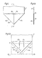
- Figure 1 is a front elevation of the IBC located on the cradle
- an IBC 1 of approximate capacity 1 m 3 in the form of a nominal cuboid bag is located on a cradle 2 which is resting on a surface 3, which may be the ground or another IBC.
- the cradle has a pair of supporting members 4a, 4b spaced apart only by a pair of cross members 5 connecting the lower edges of the supporting members 4a, 4b.
- a pair of auxiliary members 6a, 6b are provided, each being disposed outwardly of, and parallel to, the respective supporting members 4a, 4b.
- These auxiliary members 6a, 6b are connected to their respective supporting members 4a, 4b by extensions 7a, 7b of the cross-members 5 and by transverse members 8a, 8b at their lower edges, and by transverse members 9a, 9b at their upper edges.
- auxiliary members 6a, 6b and the supporting members 4a, 4b, together with the transverse members 8a, 8b, 9a, 9b, associated therewith thus define box-like structures having open ends 10a, 10b.
- the dimensions of the members is such that the tines 11 a, 11 b (shown dotted in Figures 2 and 3) of a fork-lift truck can be inserted into the box-like structures through their open ends 10a, 10b.
- the transverse members 9a, 9b above the supporting members 4a, 4b enable the cradle to be lifted, with the IBC, by the tines of a fork-lift truck inserted into the box-like structures.
- the dimension of the components are such that the openings 10a, 10b have a width of the order of 15-20 cm and a height of 5-8 cm, and are spaced apart by 70-85 cm. If the supporting members 4a, 4b have a thickness of about 2.5 cm, the distance between the facing sides of the supporting members 4a, 4b will thus be about 65-80 cm. If the transverse members 8a, 8b, 9a, 9b, and the cross-members 5 have a thickness of about 1 cm, the total height of the cradle will be about 7-10 cm.
- the IBC is preferably filled while located on the cradle as this enables the requisite degree of "sag” to be achieved and, by using conventional vibratory filling devices, the top of the IBC can then be rendered essentially flat.
- the IBC has an impermeable lining, is may be advantageous, after filling, to evacuate the air inside the lining. This renders the filled IBC relatively rigid.
- lifting straps can be fastened to the IBC or made integral therewith, preferably there are no such straps or lifting means so that the IBC can only be handled by means of the cradle so that the formation of a convex top to the IBC is avoided.
- the material of the IBC can be less substantial than is conventional, thus giving cost savings. Since the cradle serves essentially only a stabilising function, it too can be less substantial than conventional pallets. Conveniently the cradle is made from timber.
- the IBC is preferaly of tubular configuration with its bottom formed, as in conventional bag or sack technology by folding and sealing the material at one end of the tube.
- the bottom may be sealed by stitching, by an adhesive, and/or by welding, and may incorporate a reinforcing or sealing patch.
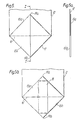
- the bottom is formed by folding one end of the tube, while the latter is in the collapsed, "lay-flat” state, into an approximately square configuration, followed by folding the opposite "free" corners of the square towards one another to form a generally hexagonal shape having a length equal to the lay-flat width of the tube and four sides of equal length disposed in two opposite pairs with a right angle between adjacent equal length sides.
- the other two sides of the hexagon will not be disposed at right angles to adjacent sides but may, in some cases, also have a length equal to those of the aforesaid four sides.
- the IBC can be accurately positioned during filling.
- the bottom of the IBC is preferably of such a hexagonal configuration with the width of the hexagonal equal to the length of the sides of the hexagon that are parallel to its length.
- this width will exceed the spacing between the support members of the cradle.
- the light fastening may be, for example, stitching with a suitable thread, and/or a layer, line, or spots of an adhesive, and/or one or more strips of adhesive tape.
- the cradle is dimensioned so that the tines of a fork-lift truck can be inserted in the openings 10a, 10b, and to this end, the overall width of the space between the support members 4a, 4b is about 70 cm while the overall width of the cradle is about 120 cm.
- Such a cradle can conveniently support an - IBC which, when filled is of approximate cylindrical configuration having a diameter of about 120 cm.
- an IBC can be formed from a tube of lay-flat width of about 188 cm.
- the bottom of the IBC can be formed, as shown in Figures 4 to 9 and 4a to 8a, by folding the lay-flat tube 12. First the bottom corners 13a, 13b are folded, about lines 14a, 14b respectively and tucked inside the tube (see Figures 4 and 4a). Two triangular shaped flaps 15a, 15b are thus formed at the end of the tube. One flap 15a is then folded upwards about line 16 (shown dotted in Figure 5) to give a square configuration 17.
- a reinforcing patch 22 is then applied to the area BCEF (see Figures 7, 7a).
- the distance between sides BC and FE can be reduced by folding the opposed corners 19a, 19b of square 17 along lines 20a', 20b' (see Figure 6b) so that the corners 19a, 19b overlap, to give a narrower hexagon AB'C'DE'F' that could fit between the support members 4a, 4b of the cradle. While such an arrangement could be utilised, the corners B'C'E'F' of the narrower hexagon AB'C'DE'F' no longer describe a square.
- a square base BCEF is desirable in order to give the IBC its optimum capacity and to improve the appearance and stability of the filled IBC on the cradle.
- These folded back portions 23a, 23b are fastened to the outer sides 25a, 25b of the rest of the flaps 15a, 15b by means of a releasable fastening, e.g. by means of adhesive tape strips 26 (see Figures 8, 8a, and 9) and/or by a line or spots of a weak adhesive (not shown).
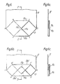
- the IBC is first placed (see Figure 10) on the cradle with the narrow hexagon AB"C"DE”F" between the support members 4a, 4b with the sides B"C” and F"E" parallel to the support members 4a, 4b.
- the top of the IBC is then clamped open by a clamp device 27 (see Figure 11).
- a clamp device 27 On filling the IBC (see Figure 12) the fastening, e.g. tape 26, holding portions 23a, 23b back is broken by the action of the IBC base opening out to accommodate the contents (which are not shown in Figure 12).
- the clamp 27 is released and the top of the IBC closed, for example by folding and sealing the upper ends 28 of the IBC over the contents and/or by the application of a separate cover member (not shown) which is fastened to the top of the IBC, e.g. by shrink wrapping.
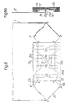
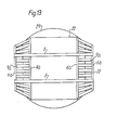
- the cradle is preferably of octagonal configuration as shown in Figure 13.
Description
- This invention relates to flexible intermediate bulk containers, which are hereinafter referred to as IBC's. Such containers, which are often in the form of bags or sacks fabricated from a woven fabric, e.g. woven from polyolefin fibres or ribbons, often with an impervious liner, e.g, as a separate inner plastics sack or having an inner or outer plastics laminated coating, are widely used for transporting powdery or granular materials, such as chemicals, e.g. fertilizers, when it is desired that a unit package should be of the order of 0.5 to 3 m3. Typically IBC's have a capacity of 1 to 1.5 m3.
- Heretofore such IBC's have been provided with lifting straps or slings sewn or otherwise attached to the container or formed integrally therewith. When lifted by such means, the contents of the IBC are compressed and tend to give the IBC a convex top. This gives rise to problems when it is desired to stack the IBC's several high since the convex top tends to give rise to stack instability with consequent safety hazards. Also, since the IBC's are lifted from the top, it is often necessary for an operative to climb on to the top of the stack to attach the slings etc. to the lifting device.
- In some cases the IBC's are transported on pallets of the conventional type, generally with one IBC per pallet, so that the palletised IBC can be moved by means of conventional fork-lift trucks as described in "Conserva" 16 (1968), 10,
page 250. Formation of a convex top to the IBC, with consequent stacking instability is still liable to occur, particularly where the IBC is lifted by slings etc. on to the pallet. - We have devised a method of overcoming this problem.
- Accordingly we provide in combination a filled IBC and a cradle for supporting said IBC on a surface, said cradle comprising a pair of supporting members provided with transverse members extending outwardly from the upper edges thereof, disposed beneath the base of the IBC and held spaced apart by cross members thus providing a space between said supporting members within which the base of the IBC can rest upon said surface, the spacing, height, and thickness of said supporting members being such that said supporting and transverse members support outer portions of the base of the IBC above said surface by a distance sufficient to permit the tines of a fork-lift truck to be inserted beneath said transverse members thereby enabling said filled IBC and cradle to be lifted from said surface by said fork-lift truck tines.
- One embodiment of the invention is illustrated by the accompanying drawings wherein Figure 1 is a front elevation of the IBC located on the cradle,
- Figure 2 is a side elevation of the IBC located on the cradle,
- Figure 3 is a plan of the cradle,
- Figures 4 to 9 are diagrammatic elevations showing the stages in the formation of the bottom of an IBC suitable for use with the cradle. Figures 8 and 9 are front and back elevations respectively of the final stage.
- Figures 4a to 8a show sections along the lines I-I of Figures 4 to 8 respectively,
- Figures 4b, 5b, 6b and 6c correspond to Figures 4, 5, 6 and 6a respectively showing possible modifications.
- Figures 10 to 12 are sections through an IBC of the type shown in Figures 8 and 9 positioned in a cradle showing the various stages in filling. In
- Figures 10 to 12 some of the layers of material forming the base have been omitted for simplicity.
- In Figures 4a to 8a, and 10 to 12, the component layers are shown separated slightly for clarity.
- Figure 13 is a view, from the underside, of a filled IBC as shown in Figure 12 on a slightly modified cradle.
- In Figures 1 and 2 an IBC 1, of approximate capacity 1 m3 in the form of a nominal cuboid bag is located on a
cradle 2 which is resting on a surface 3, which may be the ground or another IBC. - The cradle has a pair of supporting
members cross members 5 connecting the lower edges of the supportingmembers members members cross-members 5 and bytransverse members 8a, 8b at their lower edges, and bytransverse members - The auxiliary members 6a, 6b and the supporting
members transverse members - The dimensions of the members is such that the
tines 11 a, 11 b (shown dotted in Figures 2 and 3) of a fork-lift truck can be inserted into the box-like structures through their open ends 10a, 10b. Thetransverse members members - Typically the dimension of the components are such that the openings 10a, 10b have a width of the order of 15-20 cm and a height of 5-8 cm, and are spaced apart by 70-85 cm. If the supporting
members members transverse members cross-members 5 have a thickness of about 1 cm, the total height of the cradle will be about 7-10 cm. - Between the box-like structures there is thus a space of approximate width 65-80 cm and 7-10 cm height. The IBC sags into this space so that it rests upon the surface 3: hence the bulk of the weight (and of any IBC's stacked on top of IBC 1) is borne by the base of IBC 1 rather than by the
cradle 2. In turn this sagging of the IBC may, in some cases, give the top of the IBC a slightly concave configuration as shown by thedotted line 12 in Figure 1. - The IBC is preferably filled while located on the cradle as this enables the requisite degree of "sag" to be achieved and, by using conventional vibratory filling devices, the top of the IBC can then be rendered essentially flat. Where the IBC has an impermeable lining, is may be advantageous, after filling, to evacuate the air inside the lining. This renders the filled IBC relatively rigid.
- While lifting straps can be fastened to the IBC or made integral therewith, preferably there are no such straps or lifting means so that the IBC can only be handled by means of the cradle so that the formation of a convex top to the IBC is avoided.
- Where there are no lifting straps etc., the material of the IBC can be less substantial than is conventional, thus giving cost savings. Since the cradle serves essentially only a stabilising function, it too can be less substantial than conventional pallets. Conveniently the cradle is made from timber.
- In order to enable the IBC to be filled while located on the cradle, it is desirable that means are provided to accurately position the empty IBC on the cradle so that, when filled, the IBC is evenly supported by the cradle.
- The IBC is preferaly of tubular configuration with its bottom formed, as in conventional bag or sack technology by folding and sealing the material at one end of the tube. Depending on the materials emploued for the manufacture of the IBC, the bottom may be sealed by stitching, by an adhesive, and/or by welding, and may incorporate a reinforcing or sealing patch. Conveniently the bottom is formed by folding one end of the tube, while the latter is in the collapsed, "lay-flat" state, into an approximately square configuration, followed by folding the opposite "free" corners of the square towards one another to form a generally hexagonal shape having a length equal to the lay-flat width of the tube and four sides of equal length disposed in two opposite pairs with a right angle between adjacent equal length sides. The other two sides of the hexagon will not be disposed at right angles to adjacent sides but may, in some cases, also have a length equal to those of the aforesaid four sides.
- By forming the bottom of the IBC of such a size that it has a hexagonal configuration so that the hexagon has a length equal to the lay-flat width of the tube, parallel opposed sides, one pair of opposed sides parallel to the lenth of the hexagon, and a width such that the hexagon can fit between the supporting members of the cradle with those sides of the hexagon which are parallel to its length being arranged parallel to the support members, the IBC can be accurately positioned during filling.
- However, for optimum capacity, appearance, and stability of the filled IBC, the bottom of the IBC is preferably of such a hexagonal configuration with the width of the hexagonal equal to the length of the sides of the hexagon that are parallel to its length.
- In many cases this width will exceed the spacing between the support members of the cradle.
- We have found however that if portions of the bottom of the IBC are folded back, along lines parallel to the length of the hexagon, to give a bottom of width suitable to fit between the support members of the cradle, and the folded back portions lightly fastened to the sides of the IBC, on filling the IBC, the fastening can be broken to release these folded back portions.
- The light fastening may be, for example, stitching with a suitable thread, and/or a layer, line, or spots of an adhesive, and/or one or more strips of adhesive tape.
- In order to obtain satisfactory filling of the container and release of the folded back portions, it is preferred to clamp the top of the IBC during the filling operation.
- As mentioned above, the cradle is dimensioned so that the tines of a fork-lift truck can be inserted in the openings 10a, 10b, and to this end, the overall width of the space between the
support members - Such a cradle can conveniently support an-IBC which, when filled is of approximate cylindrical configuration having a diameter of about 120 cm. Such an IBC can be formed from a tube of lay-flat width of about 188 cm.
- The bottom of the IBC can be formed, as shown in Figures 4 to 9 and 4a to 8a, by folding the lay-
flat tube 12. First thebottom corners 13a, 13b are folded, aboutlines 14a, 14b respectively and tucked inside the tube (see Figures 4 and 4a). Two triangular shapedflaps 15a, 15b are thus formed at the end of the tube. One flap 15a is then folded upwards about line 16 (shown dotted in Figure 5) to give asquare configuration 17. - It will be appreciated that, if desired, the lines along which the
corners 13a, 13b and flap 15a are folded may be displaced to 14a', 14b', and 16' respectively (see Figure 4b) so that an overlap 18 (see Figure 5b) is formed. - The free
opposed corners 19a, 19b ofsquare 17 are then folded towards each other (see Figures 6, 6a) about lines 20a, 20b to give ahexagonal configuration 21 denoted in Figure 6 as hexagon ABCDEF. This hexagon has opposed parallel sides AB, ED; BC, FE; and CD, AF and four sides AB, CD, DE, and FA of equal length. - A reinforcing
patch 22 is then applied to the area BCEF (see Figures 7, 7a). - By geometry it is seen that if the
opposed corners 19a, 19b are folded so that they just meet, corners BCEF of the hexagon describe a square. Then, if the lay-flat width of thetube 12 is 188 cm, the width of thehexagon 21, i.e. the distance between the opposed parallel sides BC and FE, is 94 cm, which is in an excess of the spacing (about 70 cm) between thesupport members opposed corners 19a, 19b ofsquare 17 along lines 20a', 20b' (see Figure 6b) so that thecorners 19a, 19b overlap, to give a narrower hexagon AB'C'DE'F' that could fit between thesupport members - A square base BCEF is desirable in order to give the IBC its optimum capacity and to improve the appearance and stability of the filled IBC on the cradle.
- In order to permit the bottom to fit between the
support members opposed portions 23a, 23b of the hexagon 21 (each portion containing one of the opposed sides BC, EF of the hexagon) are folded back, aboutlines 24a 24b (see Figure 8, 8a, 9) to give a narrower hexagon AB"C"DE"F" of size such that it can fit between thesupport members support members - These folded back
portions 23a, 23b are fastened to theouter sides 25a, 25b of the rest of theflaps 15a, 15b by means of a releasable fastening, e.g. by means of adhesive tape strips 26 (see Figures 8, 8a, and 9) and/or by a line or spots of a weak adhesive (not shown). - In use the IBC is first placed (see Figure 10) on the cradle with the narrow hexagon AB"C"DE"F" between the
support members support members - The top of the IBC is then clamped open by a clamp device 27 (see Figure 11). On filling the IBC (see Figure 12) the fastening,
e.g. tape 26, holdingportions 23a, 23b back is broken by the action of the IBC base opening out to accommodate the contents (which are not shown in Figure 12). - After filling, the
clamp 27 is released and the top of the IBC closed, for example by folding and sealing the upper ends 28 of the IBC over the contents and/or by the application of a separate cover member (not shown) which is fastened to the top of the IBC, e.g. by shrink wrapping. - Where the filled IBC 29 is of generally cylindrical configuration, i.e. as is obtained using an IBC made, as described above, from a tubular material, the cradle is preferably of octagonal configuration as shown in Figure 13.
Claims (8)
Applications Claiming Priority (4)
| Application Number | Priority Date | Filing Date | Title |
|---|---|---|---|
| GB8135731 | 1981-11-26 | ||
| GB8135731 | 1981-11-26 | ||
| GB8219485 | 1982-07-06 | ||
| GB8219485 | 1982-07-06 |
Publications (2)
| Publication Number | Publication Date |
|---|---|
| EP0080839A1 EP0080839A1 (en) | 1983-06-08 |
| EP0080839B1 true EP0080839B1 (en) | 1986-04-09 |
Family
ID=26281384
Family Applications (1)
| Application Number | Title | Priority Date | Filing Date |
|---|---|---|---|
| EP82306155A Expired EP0080839B1 (en) | 1981-11-26 | 1982-11-18 | Intermediate bulk containers |
Country Status (6)
| Country | Link |
|---|---|
| US (1) | US4830191A (en) |
| EP (1) | EP0080839B1 (en) |
| DE (1) | DE3270482D1 (en) |
| DK (1) | DK156250C (en) |
| IE (1) | IE53566B1 (en) |
| NO (1) | NO159845C (en) |
Families Citing this family (22)
| Publication number | Priority date | Publication date | Assignee | Title |
|---|---|---|---|---|
| EP0080839B1 (en) * | 1981-11-26 | 1986-04-09 | Imperial Chemical Industries Plc | Intermediate bulk containers |
| GB8427337D0 (en) * | 1984-10-29 | 1984-12-05 | Ici Plc | Intermediate bulk containers |
| GB8624697D0 (en) * | 1986-10-15 | 1986-11-19 | Ici Plc | Intermediate bulk containers |
| AU1190592A (en) * | 1991-02-04 | 1992-09-07 | Wisapak Oy Ab | Shipping package and method for its fabrication |
| US5318219A (en) * | 1992-06-05 | 1994-06-07 | Four M Manufacturing Group Of Cpc, Inc. | Collapsible pallet mounted container |
| US5542541A (en) * | 1994-08-31 | 1996-08-06 | Four M Manufacturing Group Of Cpc, Inc. | Multi-sided collapsible container |
| WO1996009952A1 (en) * | 1994-09-27 | 1996-04-04 | Donnelly Corporation | Modular panel assembly |
| US5785175A (en) * | 1996-06-04 | 1998-07-28 | Cholsaipant; Natthi | Flexible bulk bag with improved base |
| US20050196080A1 (en) * | 1999-12-09 | 2005-09-08 | Stone Michael G. | Octagon shaped stackable flexible intermediate bulk container and method of manufacture |
| FR2818619B1 (en) * | 2000-12-21 | 2003-06-13 | Europ De Conception De Contene | PALLET FOR THE STORAGE AND / OR TRANSPORT OF OBJECTS |
| SE524755C2 (en) * | 2001-11-26 | 2004-09-28 | Natthi Cholsaipant | Large bag with a seamless bottom and method of manufacturing a large bag |
| US20050063623A1 (en) * | 2002-06-20 | 2005-03-24 | Eisenbarth Bradley Matthew | Stackable and forklift positionable bulk bags |
| US20040264814A1 (en) * | 2002-06-20 | 2004-12-30 | Eisenbarth Bradley Matthew | Stackable and forklift positionable bulk bags |
| CA2394195C (en) * | 2002-07-18 | 2010-11-09 | Gerald Lynn Baker | Bulk bag with integral pallets |
| US6926144B1 (en) | 2002-08-27 | 2005-08-09 | Daniel R. Schnaars, Jr. | Bulk bag pallet tube apparatus |
| CA2409471C (en) * | 2002-10-23 | 2010-10-12 | Lsi - Lift Systems Incorporated | Bulk bag and rigid fork lift tine receiving member combination |
| US6935500B1 (en) | 2002-12-05 | 2005-08-30 | Daniel R. Schnaars | Bulk bag with support system |
| KR101075214B1 (en) * | 2003-02-13 | 2011-10-19 | 텔랍 인코퍼레이션 | Bulk bag |
| US7591370B1 (en) | 2004-10-18 | 2009-09-22 | Schnaars Daniel R | Pot belly bag with a pair of sleeves |
| CA2496254C (en) * | 2005-02-07 | 2013-04-16 | Lsi-Lift Systems Incorporated | Bulk bag handling assembly |
| US7757851B2 (en) * | 2005-11-15 | 2010-07-20 | Schnaars Daniel R | Pot belly bag |
| US20170022016A1 (en) * | 2015-07-24 | 2017-01-26 | Potters Industries, Llc | Bulk Bag Design With Pass-Through Forklift Tine Sleeves and Method of Use |
Family Cites Families (27)
| Publication number | Priority date | Publication date | Assignee | Title |
|---|---|---|---|---|
| CA680622A (en) * | 1964-02-25 | J. Desbois Theodore | Folding pallet | |
| US658147A (en) * | 1900-03-01 | 1900-09-18 | John S Herriott | Sample-bag. |
| US1767274A (en) * | 1927-07-05 | 1930-06-24 | Martin T Broderick | Convertible long and short shopping bag |
| GB354355A (en) * | 1930-05-05 | 1931-08-05 | John Earl Ransom Simons | A combined displaying and carrying container |
| US2751140A (en) * | 1953-04-06 | 1956-06-19 | Bemis Bro Bag Co | Bag |
| US2698696A (en) * | 1953-12-24 | 1955-01-04 | American Cyanamid Co | Shipping unit and lifting skid therefor |
| US2913205A (en) * | 1956-02-27 | 1959-11-17 | Theodore J Desbois | Pallet |
| GB847036A (en) * | 1958-06-13 | 1960-09-07 | Ici Ltd | Pallet with separable parts |
| US3282621A (en) * | 1963-12-26 | 1966-11-01 | Thomas G Peterson | Combination lifting pallet and collapsible storage and shipping container |
| US3337036A (en) * | 1965-04-15 | 1967-08-22 | Thomas G Peterson | Disposable and collapsible storage and shipping container |
| US3494490A (en) * | 1967-09-26 | 1970-02-10 | Melvin E Shell | Method and apparatus for handling stacked materials |
| US3495762A (en) * | 1968-06-03 | 1970-02-17 | Frank A Verbic | Disposable bag for incinerator ashes and the like |
| US3477631A (en) * | 1968-08-16 | 1969-11-11 | Sonoco Products Co | Combination pallet and container |
| GB1257297A (en) * | 1970-02-11 | 1971-12-15 | ||
| DE2051026A1 (en) * | 1970-10-17 | 1972-04-20 | Badische Anilin- & Soda-Fabrik AG, 6700 Ludwigshafen; J.F. Werz jun. KG, 7141 Oberstenfeld | Loading unit |
| FR2231575A1 (en) * | 1973-05-30 | 1974-12-27 | Thibault Michel | Pallet for sacks of slidable material - has inclined strips forming V-section floor to prevent sliding |
| US3921892A (en) * | 1974-05-28 | 1975-11-25 | Henry J Macie | Bottom dump container for bulk material |
| US3944070A (en) * | 1974-09-09 | 1976-03-16 | Phillips Petroleum Company | Pallet and an integral package utilizing the pallet |
| FR2377942A1 (en) * | 1977-01-20 | 1978-08-18 | Erb Rene | FOLDABLE FLEXIBLE CONTAINER |
| US4165024A (en) * | 1977-09-09 | 1979-08-21 | Cato Oil And Grease Co. | Bulk shipping container |
| DE2838859C2 (en) * | 1978-09-06 | 1984-06-28 | Windmöller & Hölscher, 4540 Lengerich | Resealable cross-bottom sack |
| FR2475500A1 (en) * | 1980-02-13 | 1981-08-14 | Omya Sa | Pallet for bagged granular material - has frame to raise outside edges of bags and prevent over reaching |
| EP0040476B1 (en) * | 1980-05-17 | 1983-11-02 | Marston Palmer Ltd. | Intermediate bulk container for liquids |
| DE3171497D1 (en) * | 1980-10-13 | 1985-08-29 | Ici Plc | Transportable load |
| NO149203C (en) * | 1981-04-07 | 1984-03-07 | Norpapp Ind As | DEVICE AT A PALLBOX. |
| EP0080839B1 (en) * | 1981-11-26 | 1986-04-09 | Imperial Chemical Industries Plc | Intermediate bulk containers |
| US4585143A (en) * | 1984-01-25 | 1986-04-29 | Boise Cascade Corporation | Liquid container |
-
1982
- 1982-11-18 EP EP82306155A patent/EP0080839B1/en not_active Expired
- 1982-11-18 DE DE8282306155T patent/DE3270482D1/en not_active Expired
- 1982-11-22 IE IE2770/82A patent/IE53566B1/en not_active IP Right Cessation
- 1982-11-25 NO NO823959A patent/NO159845C/en unknown
- 1982-11-26 DK DK528682A patent/DK156250C/en not_active IP Right Cessation
-
1988
- 1988-08-24 US US07/236,284 patent/US4830191A/en not_active Expired - Fee Related
Also Published As
| Publication number | Publication date |
|---|---|
| NO159845C (en) | 1989-02-15 |
| DE3270482D1 (en) | 1986-05-15 |
| IE822770L (en) | 1983-05-26 |
| NO823959L (en) | 1983-05-27 |
| US4830191A (en) | 1989-05-16 |
| DK156250C (en) | 1989-12-11 |
| EP0080839A1 (en) | 1983-06-08 |
| IE53566B1 (en) | 1988-12-07 |
| DK528682A (en) | 1983-05-27 |
| NO159845B (en) | 1988-11-07 |
| DK156250B (en) | 1989-07-17 |
Similar Documents
| Publication | Publication Date | Title |
|---|---|---|
| EP0080839B1 (en) | Intermediate bulk containers | |
| EP0040476B1 (en) | Intermediate bulk container for liquids | |
| US4499599A (en) | Stackable flexible bulk container | |
| US4194652A (en) | Collapsible receptacle for flowable materials | |
| US4224970A (en) | Collapsible receptacle for flowable materials | |
| KR100188806B1 (en) | Package for transporting and storing bulk goods | |
| US4300608A (en) | Self-raising strap loop | |
| US4143796A (en) | Collapsible receptacle for flowable materials | |
| US4781475A (en) | Reinforced bulk bag | |
| JP2788028B2 (en) | Containers for materials such as free flowing fluids | |
| US2698696A (en) | Shipping unit and lifting skid therefor | |
| US6012266A (en) | Method for packing bulk goods and a container for bulk goods | |
| US8365912B2 (en) | Wire containment structure including container and bag | |
| EP0735974B1 (en) | Containers | |
| DK457487D0 (en) | DEVICE FOR HANDLING BAGS FOR FILLING THE FINE CORN OR GRANULATED MATERIAL | |
| US20010027826A1 (en) | Flexible intermediate bulk container with fork lift guide | |
| JPH0624487A (en) | Container for grain cargo material, fluid and equivalent item | |
| EP3348496B1 (en) | Seal assembly system | |
| JP3026507B2 (en) | Method and apparatus for forming unit container by wrap, and method for packaging fluid | |
| GB2050298A (en) | Collapsible receptacle with integral sling | |
| EP0180379A2 (en) | Intermediate bulk containers | |
| EP3643642A1 (en) | Packaging bag | |
| CA1230563A (en) | Intermediate bulk containers | |
| EP0589483A1 (en) | Intermediate bulk container and method of packaging | |
| EP0265103B1 (en) | Intermediate bulk containers |
Legal Events
| Date | Code | Title | Description |
|---|---|---|---|
| PUAI | Public reference made under article 153(3) epc to a published international application that has entered the european phase |
Free format text: ORIGINAL CODE: 0009012 |
|
| AK | Designated contracting states |
Designated state(s): BE DE FR GB NL SE |
|
| 17P | Request for examination filed |
Effective date: 19831003 |
|
| GRAA | (expected) grant |
Free format text: ORIGINAL CODE: 0009210 |
|
| AK | Designated contracting states |
Kind code of ref document: B1 Designated state(s): BE DE FR GB NL SE |
|
| REF | Corresponds to: |
Ref document number: 3270482 Country of ref document: DE Date of ref document: 19860515 |
|
| ET | Fr: translation filed | ||
| PLBE | No opposition filed within time limit |
Free format text: ORIGINAL CODE: 0009261 |
|
| STAA | Information on the status of an ep patent application or granted ep patent |
Free format text: STATUS: NO OPPOSITION FILED WITHIN TIME LIMIT |
|
| 26N | No opposition filed | ||
| PGFP | Annual fee paid to national office [announced via postgrant information from national office to epo] |
Ref country code: FR Payment date: 19941007 Year of fee payment: 13 |
|
| PGFP | Annual fee paid to national office [announced via postgrant information from national office to epo] |
Ref country code: SE Payment date: 19941014 Year of fee payment: 13 |
|
| PGFP | Annual fee paid to national office [announced via postgrant information from national office to epo] |
Ref country code: BE Payment date: 19941020 Year of fee payment: 13 |
|
| PGFP | Annual fee paid to national office [announced via postgrant information from national office to epo] |
Ref country code: DE Payment date: 19941024 Year of fee payment: 13 |
|
| PGFP | Annual fee paid to national office [announced via postgrant information from national office to epo] |
Ref country code: NL Payment date: 19941130 Year of fee payment: 13 |
|
| EAL | Se: european patent in force in sweden |
Ref document number: 82306155.1 |
|
| REG | Reference to a national code |
Ref country code: GB Ref legal event code: 746 Effective date: 19950322 |
|
| PG25 | Lapsed in a contracting state [announced via postgrant information from national office to epo] |
Ref country code: SE Effective date: 19951119 |
|
| PG25 | Lapsed in a contracting state [announced via postgrant information from national office to epo] |
Ref country code: BE Effective date: 19951130 |
|
| BERE | Be: lapsed |
Owner name: IMPERIAL CHEMICAL INDUSTRIES P.L.C. Effective date: 19951130 |
|
| PG25 | Lapsed in a contracting state [announced via postgrant information from national office to epo] |
Ref country code: NL Effective date: 19960601 |
|
| PG25 | Lapsed in a contracting state [announced via postgrant information from national office to epo] |
Ref country code: FR Effective date: 19960731 |
|
| NLV4 | Nl: lapsed or anulled due to non-payment of the annual fee |
Effective date: 19960601 |
|
| PG25 | Lapsed in a contracting state [announced via postgrant information from national office to epo] |
Ref country code: DE Effective date: 19960801 |
|
| EUG | Se: european patent has lapsed |
Ref document number: 82306155.1 |
|
| REG | Reference to a national code |
Ref country code: FR Ref legal event code: ST |
|
| PGFP | Annual fee paid to national office [announced via postgrant information from national office to epo] |
Ref country code: GB Payment date: 19971017 Year of fee payment: 16 |
|
| PG25 | Lapsed in a contracting state [announced via postgrant information from national office to epo] |
Ref country code: GB Free format text: LAPSE BECAUSE OF NON-PAYMENT OF DUE FEES Effective date: 19981118 |
|
| GBPC | Gb: european patent ceased through non-payment of renewal fee |
Effective date: 19981118 |