EP0287969A2 - Selbstverschliessendes Abgabeventil - Google Patents
Selbstverschliessendes Abgabeventil Download PDFInfo
- Publication number
- EP0287969A2 EP0287969A2 EP88106045A EP88106045A EP0287969A2 EP 0287969 A2 EP0287969 A2 EP 0287969A2 EP 88106045 A EP88106045 A EP 88106045A EP 88106045 A EP88106045 A EP 88106045A EP 0287969 A2 EP0287969 A2 EP 0287969A2
- Authority
- EP
- European Patent Office
- Prior art keywords
- orifice
- valve
- plug
- actuator
- strip
- Prior art date
- Legal status (The legal status is an assumption and is not a legal conclusion. Google has not performed a legal analysis and makes no representation as to the accuracy of the status listed.)
- Granted
Links
Images

Classifications
-
- B—PERFORMING OPERATIONS; TRANSPORTING
- B65—CONVEYING; PACKING; STORING; HANDLING THIN OR FILAMENTARY MATERIAL
- B65D—CONTAINERS FOR STORAGE OR TRANSPORT OF ARTICLES OR MATERIALS, e.g. BAGS, BARRELS, BOTTLES, BOXES, CANS, CARTONS, CRATES, DRUMS, JARS, TANKS, HOPPERS, FORWARDING CONTAINERS; ACCESSORIES, CLOSURES, OR FITTINGS THEREFOR; PACKAGING ELEMENTS; PACKAGES
- B65D47/00—Closures with filling and discharging, or with discharging, devices
- B65D47/04—Closures with discharging devices other than pumps
- B65D47/20—Closures with discharging devices other than pumps comprising hand-operated members for controlling discharge
Definitions
- My invention relates to dispensing closure valves for containers and, more particularly, to a self closing molded plastic valve for containers of the flexible wall type.
- a dispensing closure valve is attached to the bag for dispensing the contents, such as milk or, more commonly, wine.
- Another type of beverage package is constructed of a leak proof cardboard aluminum foil laminate.
- the dispenser valve is attached to the lower portion of the package and is subjected to fluid pressure.
- the beverage supplier packages the beverage and supplies the local supermarket where the package is placed on the shelves and made available for purchase by the consumer. Following the purchase of the product, the consumer dispenses the beverage into an awaiting cup by simply applying finger pressure to a simple push button or actuator. That action opens the valve; and beverage flows out the spout and fills the waiting cup.
- Unlike beverage packaging constructions using a cap even a recloseable cap, one need not pick up and tilt over the container to pour out the beverage.
- valves must thus initially have a suitable "shelf life" over which it does not leak. Further the beverage is not always consumed at one sitting, except perhaps in the case of Australians. Hence to be effective, the valve, which is subjected to the hydrostatic pressures of the standing confined fluid, cannot allow any of the confined fluid to seep. Beverage containers of this type are not intended to be re-usable. Consequently when the container is emptied, the package is discarded, whether in the garbage pail or, unfortunately all too often, along the roadside. In those packaged goods applications, the closure valve must necessarily be a low cost element of the beverage package system so as to maintain the product price overall attractive to the consumer. Bronze valves thus do not do in this application.
- valve structure may be as a means to open and close a fluid passage, it must be easy to operate. If it requires too large a force to do so or if the valve is awkward to the grip or touch, the valve is not satisfactory to this use.
- That valve structure is essentially a plug made of elastomeric material which acts as a plug on an associated fluid containing chamber.
- That valve structure is essentially a plug made of elastomeric material which acts as a plug on an associated fluid containing chamber.
- a passage is opened and fluid flows from the associated container and leaks past the distorted area.
- This type of spigot or valve in my opinion cannot withstand any reasonable pressures which may be exerted upon it as its elastomeric nature has a tendency to flex and leak.
- the type of valve shown in Bond is difficult to operate. A waitress who needs to fill wine glasses from a bulk container in the course of business who is required to frequently manipulate this valve may find that she has sore fingers and thumbs; thereafter she might unconsciously influence the customers selection of wine.
- valve that has achieved wide acceptance is manufactured by Waddington & Duval, Ltd. a company based in England.
- the valve contains a plug supported on a stem and a spring diaphragm push button combination. By manually depressing the pushbutton with the thumb, the plug is moved essentially axially and uncovers an orifice through which fluid passes. And the diaphragm spring functions to make this valve self closing.
- Waddington valve It has good flow characteristics, reasonable sealing abilities and is relatively easy to operate.
- this valve is expensive. Its elements are not formed in one piece, but four individual components, if an overcap is included, and three individual components otherwise. Each of the elements are made in a separate molding operation. They must be inventoried and assembled together. Those activities require time, space and people, which adds to the manufacturing cost.
- Another multipart self closing valve intended for application in a "bag in the box" application is presented in Hyde U.S. 4,687,123.
- An object of my invention is to provide a self closing valve spout that is of novel and inexpensive structure; It is a further object of my invention to provide a dispensing closure valve for use with packaged liquids that has an acceptable shelf life and does not allow the confined liquid to seep or leak out of the package; It is a still additional object to provide a closure valve that may be more easily manufactured than prior valves that addressed the same application and that can be manufactured from a single piece of plastic material using conventional injection molding technique.
- a one piece self closing dispensing valve of molded polymer material is used in combination with a beverage container.
- the valve is of the kind containing a movable actuator, which in response to a force applied thereto by a user, such as pressure exerted by the users finger, opens the valve to dispense liquid under force of gravity.
- a leaf spring operable over the range of actuator movement and normally biasing the actuator responds to the withdrawl of the applied force to return the actuator to its normal position and thereby close the valve.
- An integral dripless spout is defined between the actuator and the valve body; the effective cross section size of the spout is inversly dependent on the position of the actuator.
- my invention encompasses a self closing valve formed through molding of a single matrix of plastic material that includes a manually operated actuator member and a main body portion joined together by a strap or hinge in an integral or one-piece assembly.
- the main body of the valve includes a chamber containing a fluid passage or orifice in a face plate or wall.
- the actuator member supports a plug that is of slightly larger size than the orifice; and the geometry is such that as the actuator member ia folded over about the hinge into assembled position in the main body portion, the force applied to the actuator pushes the plug through the orifice into the chamber for closing the orifice.
- a spring member particularly a leaf spring, that functions with or as part of the actuator member, produces a biasing force on the actuator.
- the direction of the bias force is opposite to the prior assembling force and is sufficient to ensure that the plug is seated in the orifice in the normal closed condition of the valve.
- the actuator In operation when the actuator is pressed and forced to move, the actuator in turn moves the plug away from and to the side of the orifice over a short arcuate path and, concurrently, further tensions the spring.
- the spring together with any hydrostatic pressure of the confined fluid acting on the plug, forces the actuator back to its normal position responsive to release of the applied force, whereby the plug again seats in the orifice.
- An additional aspect to my valve is that the underside surface of the actuator confronts the chamber wall to form a channel therebetween. This channel defines a spout for deflecting the fluid released through the orifice downwardly past the free end of the actuator member and out the valve.
- the cross section area and size of the channel varies inversly as a function of the distance between the chamber wall and actuator member.
- a further aspect to the invention is the inclusion of a pair of finger grips adjacent the actuator to assist the application of a finger force to move the actuator member.
- a still additional aspect of the invention is the inclusion in this combination of a backstop or limiters to engage and block excessive reverse movement of the actuator should movement in the reverse direction beyond the normal position be attempted as a result of unusually high pressures existing in the chamber.
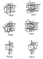
- FIG. 1 a preferred embodiment of my valve is illustrated in a front perspective view.
- the valve contains a body portion 2 containing a generally tubular shape wall 11 joined to a face plate or wall 12, not fully illustrated in this figure, a mechanical push actuator member 1, containing a raised pushbutton like actuator portion 5.
- a pair of finger grips 17 and 18, one located on each side of the actuator, are supported by and extend at right angles to walls 15 and 16, respectively. In turn the supporting walls are connected to and extend at a right angle from chamber wall 12.
- actuator 1 is integrally connected to one end of strip 4 and in turn the strip, which I characterize as a leaf spring, is integrally connected to a flexible strap formed by a recess or reduced thickness portion 3 in the strip and serves as a hinge type joint, which is described in greater detail hereafter connecting the actuator to wall 12.
- the clearance between the right and left sides of the actuator and the confronting grip member support walls is represented by 31 and 32, respectively, in the figure.
- actuator 4 is shown in an operated or depressed position as occurs when a finger force of sufficient level is applied to buttonlike actuator portion 5 and is moved through a short arcuate path toward chamber wall 12; and in which the upper end of the actuator member 1 remains essentially in the same position as before.
- the bottom or free end of the actuator is pivotable or swingable toward the wall under the applied force and swings back to the normal position illustrated in Figure 1, when the applied force is released, characteristic of the self closing feature that I present in my novel valve.
- a greater portion of the side support wall 15 for grip 17 is shown in this figure. Support wall 15 is oriented essentially parallel to its sister support wall 16 on the opposite side of the actuator.
- FIG. 3 shows the plastic valve in an unassembled condition as it might appear following molding, and better illustrates the foregoing elements and additional elements of the valve, some of which are not visible in the two preceding figures.
- a plug 10 of circular cross section is connected by a connector or stem 9 to an underside wall 6 of the actuator member.
- the plug contains a front taper 36 of frusta-conical shape and the back end has a tapered surface 37 tapered in the opposite direction.
- the actuator carries two leading edges 20 and 21, which are wedge or ramp shaped elements, on opposite side walls 7 and 8, respectively. Similar wedges or leading edges 19 and 22, the latter of which is not visible in this figure, are formed in the inner side surfaces the side support walls of the finger grips.
- the actuator section 4 carries on the underside a protruding narrow bar 34 as labeled in figure 6 that is spaced a short distance from and extends parallel to the hinge.
- a protruding narrow bar 34 as labeled in figure 6 that is spaced a short distance from and extends parallel to the hinge.
- the exact function and relationships of the wedge elements and the protruding bar are described with more exactness following the description of some addition views.
- a flat U-shaped bracket, which I refer to as a "tear off” tab 27, has its ends attached to actuator 5. This element was not illustrated in figure 1.
- the tear off tab is discussed in connection with figures 15 and 16 later in this specification.
- the skilled reader may cause to consider that the complicated structure described is a unitary or one-piece assembly. That is, all of the elements are arranged to be formed in place attached together as shown by injecting fluid plastic into a single mold, allowing the plastic to cure or solidify in the mold, and removing the assembly as one single piece. Such a process is known as injection molding. Of course other kinds of molding processes may be used to obtain the molded polymer structure illustrated as the manufacturer desires.
- the relationship in position between actuator 5 and valve body 2 upon removal from the mold depends upon the particular configuration selected by the manufacturer. Thus the particular position illustrated in figure 3 is not limiting and is merely illustrative of one such pre-assembly configuration.
- the partial section view of the valve chamber illustrated in Figure 4 is taken from the valve positioned as in Figure 2 but is rotated and is drawn to an enlarged scale to illustrate more effectively the chamber wall 12, previously described, located at the end of the tubular chamber formed by cylindrical wall 11.
- a plurality of short small diameter axially extending cylindrical ribs, not illustrated, may be included. Those ribs would be attached to and extend from wall 12 and be attached to and extend along a portion of the inner surface of wall 12 to add rigidity.
- a passage or orifice 13 is shown that is of circular cross section. The orifice is surrounded by a protruding rim 30 which protrudes into the defined chamber a short distance beyond the major flat surfaces of wall 12; recognizing, however, that this rim element is also integral with the back wall 12.
- the inner end wall of the orifice rim is surrounded by a taper 14 or seal which mates with the taper 37 on the rear side of plug 10.
- This surface is also a frusta conical surface section that tapers toward the axis of the orifice to the other or left side of wall 12.
- a groove 40 recessed into the surface of wall 12 surrounds the protruding rim. This groove weakens the wall at this location to enhance its flexibility at that location, allowing rim 30 some slight axial movement.
- the geometry of plug 10, its front tapered surface 36, rear tapered surface, which is described elsewhere in this specification, and the hollowed central section are also further illustrated together with the connecting stem 9 in Figure 4.
- Figure 5 illustrates the preferred geometry of connector 9, and is a section view taken along the lines D-D in Figure 3.
- the stem consists of two elements 9a and 9b connected to the backside of plug 10.
- Element 9a is a rectangular strip or rib and element 9b is a semi cylindrical surface, the latter of which closely adjoins the rear seal surface 37 of plug 10. The two elements give adequate strength for support of the plug and for the assembly of the valve.
- plug 10 is seated in the orifice with its tapered seal surface in mating abutting engagement with the seal in the protruding rim 30 formed in chamber wall 12.
- the stem includes a straight rib that connects to actuator wall 6 underlying the pushbutton portion 5.
- the wall 6 is positioned confronting the wall 12 and, hence, the orifice; and wall 6 is joined at an end of strip 4 with which it forms an angle of approximately 135 degrees, but which maybe any angle between 90 and 180 degrees.
- the length of the stem is such that the wall or strip 4 is under a slight tension as a result of the cooperation of bar 34 and the engagement of that bar with wall 12. That is, the juncture or seal between the plug and the orifice is sufficiently strong to preclude the leaf spring portion formed of strip 4 from assuming a relaxed untensioned condition.
- the depending wall 7 is not of uniform depth. Its bottom edge as shown extends at an angle to chamber wall 12 and to actuator wall 6, from which it depends.
- the opposite actuator wall, not illustrated, is of like construction, in as much as the construction of the valve is essentially symmetrical about the mid-section plane of the valve as viewed in Figure 1.
- the actuator In the operated position illustrated in figure 8 the actuator is pivoted into a new position with the plug positioned further within the chamber away from the chamber wall and in which the plug raised slightly off and above the axis of the orifice. And the upper semi-cylindrical surface of stem 9 abuts the upper side of the orifice wall. In this position the orifice is uncovered opening a passage through the chamber into the space between wall 12 and wall 6 of the actuator.
- the actuator wall is positioned more closely to wall 12 in this condition than in figure 4 so that the size and cross section area of the passage is reduced in the transition from the normal unoperated condition to the fully operated condition.
- the fully operated position shown is defined by the position of the bottom edge of wall 7 which, as shown, abuts the wall 12 and prevents further travel of the actuator.
- the reader understands that the plug can be moved to intermediate positions which are not illustrated in which the valve is only partially opened as when the plug is moved a minute distance off of its seat in the orifice when the actuator is only partially depressed.
- the actuator 1 is generally at a right angle with respect to the body portion 2 in the unassembled position as illustrated in Figure 3.
- the actuator is then manually swung over in an arcuate path about hinge 3 to the assembled position as represented in Figure 1.
- leading edges 19 and 20 on the actuator engage leading edges 21 and 22 on the body 2 and as the inclined wedge surfaces slide past one another they wedge or force the finger grip side walls 15 and 16 apart (and the opposed actuator wall slightly inwardly), permitting the actuator to move past those protruding surfaces.
- leading edges 19 and 21 and 20 and 22 contain flat side walls that are perpendicular to the walls from which they depend as shown in Fig. 7. As becomes apparent herinafter those sidewalls are interlock surfaces that form a positive latch or stop, which prevents the actuator from being moved back to the unassembled position.
- a better illustration of the latch elements is discussed in connection with an additional embodiment in Figure 16 to which reference may be made as desired. The advantage of the interlock or latch feature will become apparent to the reader hereinafter.
- Plug 10 is slightly larger in diameter than the orifice.
- the diameter of the plug at its maximum width can be one one-hundredth of an inch (0.010 inch) greater in diameter than the diameter of the orifice taken at its minimum width.
- leading tapered edge 36 serves both to align the plug coaxially with the orifice and, as the plug is forced therethrough, to smoothly and gradually expand the orifice opening without tearing the plastic.
- the inherent elasticity of the plastic and the added flexibility resulting from the groove 40 surrounding the orifice assists this mechanical operation.
- the spring member or strip 4 is placed in tension or flexes during this assembly process by bending it about bar 34, which abutts wall 12. Upon release of the applied force during the aseembly process, the spring action inherent in the elasticity of the plastic strip moves the plug axially to the left as shown in the drawing to a position with the rear end seal 36 of the plug seated in the tapered surface 14, shown in Figure 4, of the orifice blocking the passage.
- Leaf spring 4 stores mechanical energy and creates the spring like force in the reverse direction and biases or spring loads the actuator creating a pulling force on the plug, which firmly seats the plug in mating engagement with the orifice. Conversely, the juncture between the plug and the orifice is sufficiently strong to resist the force of the spring and retain the spring in tension and the level of the spring force is not sufficient to cause de-assembly.
- valve In normal operation the valve is assembled to the lower end of a container or reservoir, not illustrated, connected to the chamber formed by the tubular wall 11 by any suitable means, not illustrated.
- the package is filled with liquid that accesses the chamber. Consequently the outer chamber wall 12 and plug 10 are subjected to considerable hydrostatic pressure, the extent of which is dependent upon the height of the fluid in the package.
- the actuator By gripping grips 16 and 17 with the index and middle fingers and pressing the actuator button 5 with the thumb, the actuator is moved from the position shown in Figure 1 (and Figure 6) to the position illustrated in Figure 2 (and Figure 8).
- the spring strip 4 is further flexed about its pivot point to increase the tension therein and plug 10 is thus moved and raised in position as shown in Figure 8.
- the confined fluid exits the chamber through the open passage and strikes the undersurface 6 of actuator member 1.
- the actuator member deflects the fluid stream downward through the passage and the free end of the actuator member to an awaiting cup or other container, which the user supplies.
- the spring flexed strip 4 releases stored energy and moves the actuator and the plug back to the normal position.
- the orifice is re-closed, shutting off the fluid flow.
- the forward movement of the actuator is limited to the point at which the bottom edges of walls 7 and 8 abut wall 12. If for any reason the pressure within chamber 12 increases to such a level as could force the plug in the reverse direction through the passage, the slight initial movement in that direction causes the back edges of the leading edges 19 and 20 of the actuator of abut against the stops 21 and 22. The stops prevent the threatened de-assembly and enhances thus the usefulness of the valve.
- the underside surface of the actuator and the wall 12, containing orifice 13, are in a confronting relationship. Together with the side walls 15 and 16, which depend from the side edges of the upper actuator surface, the surfaces define a passage or dispensing spout, oriented perpendicular essentially to the axis of the orifice, that extends through the free end of the actuator.
- the undersurface of the actuator deflects fluid entering the spout via the orifice downwardly through and out the spout.
- the size and cross section area of the spout is variable and is inversly dependent upon the distance between walls 6 and 12 or, as alternatively viewed, is dependent inversly upon the amount of forward arcuate movement of the actuator. That is, as the actuator is moved more closely to wall 12 under an applied force, the cross section area of the spout becomes smaller. This reduction in cross section continues until the edges of the side walls 15 and 16, which serve as stops or limiters, abuts against the chamber wall 12 to define the minimum cross section thereto concurrently with the actuator then being in the fully operated position.
- a further feature of my unique construction allows the spout to be "dripless". If a partial vacuum is created in a spout following closure of a valve, the vacuum will retain or hold some fluid, which will be released or "drip" out the spout as the vacuum gradually dissipates.
- the clearance gaps 31 and 32 between the side walls 15 and 16 and the corresponding side walls 7 and 8 form vents, venting the upper end of the spout passage to the atmosphere. Hence a partial vacuum cannot form in the spout upon closure of the valve.
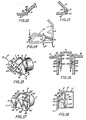
- Plug 10 and a portion of the supporting stem 9 are illustrated in section view and in a larger scale than the preceding figures, first, in the normal position in Figure 10 and, secondly, in the fully operated position in Figure 11. These illustrations correspond to the positions of those same elements presented in Figures 6 and 8 previously discussed.
- the front of the plug contains a tapered leading edge 36, essentially a frusta conical surface section, which tapers toward the axis of the plug toward the front of the plug to the right as viewed in the figure; and contains a hollowed out central region.
- the front taper acts as an expander to align the plug into the orifice during assembly of the valve and gradually expand the orifice to allow the plug to pass through.
- a tapered edge 37 also frusto conical in geometry, which also tapers toward the plug axis, but does so to the rear of the plug; to the left as viewed in the figure.
- the orifice is surrounded by a tubular wall integral with chamber wall 12 and which protrudes beyond the major rear surface of that wall.
- a shaped groove 40 in the outer surface of wall 12 surrounds the protruding orifice wall.
- the groove in the surface reduces the wall thickness at that location increasing the flexibility of the orifice wall. That is, the orifice wall can be moved axially back and forth to a slight degree, allowing the wall to yield to some extent during assembly and operation of the valve and not break or cause binding.
- the inner surface of the orifice wall contains a tapered edge 14 of similar size and geometry of the plugs rear tapered edge 36 to form a seal seat. The seal mates with the seal surface of the plug when the latter is in the normal position as illustrated in Figure 10.
- the seal tapers are shown as substantially similar, they need not be the same taper as those skilled in the art understand.
- hinge joint and spring construction are illustrated in section to an enlarged scale in Figure 12 and Figure 13 and the reader recognizes the elements previously described as the upper end of chamber wall 12, hinge 3, strip 4 and protruding rib or bar 34.
- the upper end of the wall surface contains a shoulder or ridge 35, that is a small portion of plastic raised from the major surface of the wall 12 continuous with end of hinge 3.
- the bar carried by the spring strip 4 is formed at a minor angle, a1, with respect to the plane of strip 4.
- the strip 4 is shown in the unassembled position.
- the spring member In the normal closed position of the valve and, hence the normal position of spring 4, the spring member is in slight tension, biasing or pre-loading the actuator.
- the leaf spring member When activating the valve, the leaf spring member flexes; and upon release of the valve actuator, the spring returns to the normal position with the pre-load aforedescribed.
- I symbolically represent the strip or actuator portion by a bent arm A, having two portions forming an angle of perhaps 135 degrees between the portions.
- the arm is shown first in the unassembled position, essentially upstanding at a right angle to the surface, m, representing the chamber wall or other appurtenant surface of the valve body.
- the arm is shown in the assembled normal position, attained after it has been bent or folded over about the hinge section, represented by the letter h, representing an angular positional change of a1 about a pivot point p1.
- the protruding bar abutts surface m and ridge r and is in slight tension, not illustrated.
- the arm is represented as having its end pushed further by an applied force F on arm portion 12 so as to have flexed through an additional angle b1 about the bar b, which serves as a fulcrum or pivot point p2.
- F applied force
- the actuator member may be regarded as a actuator with an integral leaf spring and the spring in turn as a coupling means which couples the actuator to the hinge; a multitude of functions within a single plastic strip.
- the leaf spring may be made as a separate strip dependent from the arm, although integrally attached. In that case the leaf spring does not serve also as the coupling to the hinge.
- the valve is molded of a flexible plastic, a polymer, that has a good memory and minimum creep characteristics to attain the spring action without losing its flexibility as required for an effective valve seat.
- polyethylene is flexible, but has poor creep and memory characteristics.
- Polypropylene on the other hand is better and some grades are excellent.
- Other plastics such as acetal and nylon have even better memory with a minimum creep, but are less flexible.
- One plastic I have found acceptable at the present time is made by Rexene. It is a homo-polymer polypropylene 11 S 30 and has a flex modulus when measure on the ASTM scale D 790 of 200,000 and a deflection temperature (ASTM D 648) of 216 degrees Fahrenheit.
- ASTM scale D 790 of 200,000
- ASTM D 648 deflection temperature
- FIG 14 An improvement to the embodiment is presented in Figure 14 in which the valve of Figure 1 is modified to incorporate a tear off tab 27. That element was briefly noted earlier in connection with the description of figure 3.
- the tab is integrally molded with a thin section 38 and 39, better illustrated in the next figure, attached to activating button 5.
- the tab forms a barrier that prevents movement of actuator 5 and, hence, prevents the valve from opening until the tab is removed. Removal is accomplished by simply tearing it off. Should the actuator be accidentally bumped while tab 27 is in place the valve, cannot open.
- FIG. 16 A section view taken along section lines F-F in figure 15 is presented in Figure 16 and illustrates more completely the attachment of the tear off tab and the high pressure interlock or limiter.
- the spacing between the interlock or stop limiter surfaces 23, 24, 25 and 26 when the valve is its normal unoperated position is a small gap represented by 28 and 29. If pressure should start to build up in the fluid chamber, the pressure exerted on the plug acts to force the plug more firmly into its sealed position in the orifice. If the pressure becomes slightly larger the pressure forces the actuator backwards so that the surfaces of the interlock limiters come in contact with each other to prevent further reverse movement of the plug and the plug cannot be forced through the orifice.
- the embodiment of the invention illustrated in figure 17 in front perspective view is of a different appearance and a slightly different construction.
- the valve of this embodiment is formed in one piece and assembled in the same way as the prior embodiments. The explanation of the functions and mode of operation, thus, need not be repeated.
- the leaf spring 50 is a strip which protrudes and depends from strip 4′ and abutts the surface of wall 12.
- the design of the geometry is such that the spring is bent slightly and, because it is of an elastic characteristic, is in a slight tension to bias the actuator member. As the actuator is moved toward the wall, the spring is bent further increasing the force that it stores. Upon release of the actuator, the spring returns the actuator to the normal position.
- leaf spring in this embodiment is not totally integrated into the plane of the actuator and/or the actuator coupling it non the less is an alternate form and provides the spring like function necessary to self closing valve action.
- this additional embodiment is useful to demonstrate the nature and scope of my invention, it is less preferred than the structure of the first embodiment.
- the valve is formed by injection molding and, as removed from the mold, appears as illustrated in Fig. 3, unassembled, as a specific example.
- the valve is left to "set” or stabilize prior to assembly into the form illustrated in Fig. 15 and Fig. 1.
- the warm plastic cools to ambient temperature.
- hinge 3 retains a "memory”; the hinge acquires a stiffening or spring like characteristic.
- hinge 3 creates a spring like return force that contributes to the biasing force created through flexing of actuator strip portion 4 about bar 34, as best illustrated by way of example in Fig. 13 and also shown in the other figures.
- the valve may be assembled immediately following the molding procedure.
- the molecules in the hinge become aligned, providing a "living" hinge; one that may be flexed indefinitely, but which does not have the spring like characteristic.
- This "living" hinge is more analogous to an ordinary metal gate hinge or leather strap hinge and non analygous to an ordinary spring loaded gate hinge.
- the hinge in this valve is flexed only once in normal use, which occurs during assembly of the valve actuator into the valve body, the advantage of indefinite flexing is unnecessary in this application.
- the spring like quality of the first described construction is preferred.
- the preferred embodiment of figures 1 and 15 and the embodiment of figure 17 includes a wax film or coating.
- the wax coating not illustrated in the figures, covers the inner part of the chamber 11 as viewed in Fig. 6 and covers all of the inner walls, including chamber wall 12 and plug 10 and is impervious to gas.
- the wax coating is applied following the assembly of the valve by inserting a nozzle from the rear side along the axis of the chamber and spraying the walls with the liquified wax.
- the coating or "osmosis barrier” is a particularly useful addition. It prevents the entry of gas, such as air, by osmosis through the polypropelene material of the valve to the confined fluid. This is important where the fluid is an alcoholic beverage. The entry of air into the alcoholic beverage even by osmosis changes the taste and quality of the beverage.
- the movement of the actuator causes the plug to break the barrier layer in the peripheral film barrier in an area around the end of plug 10, however, the remaining portions of the coating or barrier continue to serve that function inhibiting osmosis.
- An alternative to the wax is polyvinyl alcohol, which also forms a impervious film. It is noted that if the film is too strong, it may stretch rather than break. That would require modification to the design of the front end of the plug to allow it to cut through the film.
- the film layer is very thin, on the order of thickness of a layer of polish applied to an automobile when polishing the automobiles surface. Thus each of these barrier layers is applied to a thickness of at best a few ten-thousandths of an inch.
- the construction described allowed the leading edges of the actuator to spread apart side walls 15 and 16 during assembly. Consistent with my invention it is possible to have the side walls of the actuator squeezed inwardly as an alternative if the side walls of the finger grips are chosen to be more rigid. And a combination could be used with the walls of the finger grip spreading outwardly to a degree and the sidewalls of the actuator being squeezed inwardly to a degree as the actuator moves through the passage between the finger grips into assembled position.
- Stem 9 supporting the plug has one surface that is semi tubular and contains a central rib. Although that construction is preferred other configurations are also permissible, such as a stem of "T" shaped cross section.
Landscapes
- Engineering & Computer Science (AREA)
- Mechanical Engineering (AREA)
- Closures For Containers (AREA)
- Check Valves (AREA)
- Fluid-Pressure Circuits (AREA)
- Medical Preparation Storing Or Oral Administration Devices (AREA)
- Catching Or Destruction (AREA)
- Infusion, Injection, And Reservoir Apparatuses (AREA)
- Massaging Devices (AREA)
- Special Spraying Apparatus (AREA)
- Fluid-Driven Valves (AREA)
Priority Applications (1)
| Application Number | Priority Date | Filing Date | Title |
|---|---|---|---|
| AT88106045T ATE77331T1 (de) | 1987-04-23 | 1988-04-15 | Selbstverschliessendes abgabeventil. |
Applications Claiming Priority (2)
| Application Number | Priority Date | Filing Date | Title |
|---|---|---|---|
| US41305 | 1987-04-23 | ||
| US07/041,305 US4848600A (en) | 1987-04-23 | 1987-04-23 | Self closing dispensing valve |
Publications (3)
| Publication Number | Publication Date |
|---|---|
| EP0287969A2 true EP0287969A2 (de) | 1988-10-26 |
| EP0287969A3 EP0287969A3 (en) | 1989-10-18 |
| EP0287969B1 EP0287969B1 (de) | 1992-06-17 |
Family
ID=21915837
Family Applications (1)
| Application Number | Title | Priority Date | Filing Date |
|---|---|---|---|
| EP88106045A Expired - Lifetime EP0287969B1 (de) | 1987-04-23 | 1988-04-15 | Selbstverschliessendes Abgabeventil |
Country Status (7)
| Country | Link |
|---|---|
| US (1) | US4848600A (de) |
| EP (1) | EP0287969B1 (de) |
| AT (1) | ATE77331T1 (de) |
| AU (1) | AU610151B2 (de) |
| CA (1) | CA1319655C (de) |
| DE (1) | DE3872034T2 (de) |
| DK (1) | DK216688A (de) |
Cited By (2)
| Publication number | Priority date | Publication date | Assignee | Title |
|---|---|---|---|---|
| FR2791329A1 (fr) * | 1999-03-23 | 2000-09-29 | Gerry Schiavon | Recipient distributeur de matiere pateuse ou liquide et son procede de fabrication |
| WO2018229313A1 (es) * | 2017-06-14 | 2018-12-20 | Bastero Lopez Jesus Maria | Dispositivo autocierre |
Families Citing this family (20)
| Publication number | Priority date | Publication date | Assignee | Title |
|---|---|---|---|---|
| US5018559A (en) * | 1989-11-06 | 1991-05-28 | Larry J. Branan | Industrial funnel apparatus with operable lid for use with 55 gallon drums |
| USD325170S (en) | 1990-04-11 | 1992-04-07 | Frantz Dale A | Container lid with spout |
| US5102017A (en) * | 1990-06-07 | 1992-04-07 | The Procter & Gamble Company | Mechanical actuator for dispensing tap |
| US5178303A (en) * | 1991-05-17 | 1993-01-12 | Colder Products Company, Inc. | Dispensing valve apparatus |
| US5265777A (en) * | 1992-05-18 | 1993-11-30 | Primary Delivery Systems, Inc. | Push-push tilting dispensing cap system |
| US5353836A (en) * | 1992-08-19 | 1994-10-11 | Colder Products Company | Dispensing valve |
| US5439199A (en) * | 1993-12-20 | 1995-08-08 | The National Latex Products Company | Water balloon filling valve |
| AU713864B2 (en) * | 1994-02-17 | 1999-12-09 | Liqui-Box Corporation | Self-closing dispensing valve |
| US6131767A (en) * | 1998-09-09 | 2000-10-17 | Scholle Corporation | Tap for dispensing fluid |
| US6164314A (en) * | 2000-01-12 | 2000-12-26 | Intex Recreation Corp. | Oversized air valve for use with inflatable devices and method |
| EP1180370A1 (de) * | 2000-08-10 | 2002-02-20 | The Procter & Gamble Company | Wasserdampf-durchlässige, Flüssigkeits-undurchlässige, Wegwerftücher zur Abdeckung von Bett-Artikeln mit verbessertem Komfort |
| US6644512B2 (en) * | 2001-09-30 | 2003-11-11 | Gd Midea Holding Co., Ltd. | Faucet for a drinking-water dispenser |
| US7040514B2 (en) * | 2004-04-21 | 2006-05-09 | Mihail Octavian Colan | Membrane activated carbonated beverage dispenser |
| NO328579B1 (no) * | 2006-07-19 | 2010-03-22 | Smartseal As | Flerfunksjonstetningsanordning ved en ventil for en drikkebeholder |
| ITBO20070764A1 (it) * | 2007-11-20 | 2009-05-21 | Carpigiani Group Ali Spa | Macchina per la produzione e l'erogazione di prodotti alimentari ghiacciati quali granite, sorbetti e simili. |
| US8584909B2 (en) * | 2009-08-19 | 2013-11-19 | Hoffer Plastics Corporation | Dispensing tap for beverages |
| DE102011104514A1 (de) | 2010-06-18 | 2012-01-05 | Genialistix Gmbh | Selbstschließender Ausgießer |
| US9321064B2 (en) * | 2010-09-24 | 2016-04-26 | Blake Vanier | Drinking vessel with pump and methods |
| US20130098488A1 (en) * | 2011-10-21 | 2013-04-25 | Michael H. Weems | High pressure polymer valve plug components and systems |
| US10913582B2 (en) * | 2019-06-27 | 2021-02-09 | Henkel IP & Holding GmbH | Tap dispenser lock device for container |
Family Cites Families (25)
| Publication number | Priority date | Publication date | Assignee | Title |
|---|---|---|---|---|
| US2272798A (en) * | 1938-10-26 | 1942-02-10 | Edward R Hacmac | Dispensing device for containers |
| US2502821A (en) * | 1947-11-05 | 1950-04-04 | Brauner Pincus | Liquid dispensing device |
| US2857919A (en) * | 1956-12-18 | 1958-10-28 | Gillette Co | Dispenser |
| US3120908A (en) * | 1961-03-10 | 1964-02-11 | Continental Can Co | One-piece plastic resealing spout |
| US3187965A (en) * | 1964-05-12 | 1965-06-08 | David L Bourget | Spout for milk container |
| US3315850A (en) * | 1965-04-29 | 1967-04-25 | Magi Pak Corp | Disposable valved spout |
| US3584834A (en) * | 1967-09-21 | 1971-06-15 | Otto S Reid | Manually operable elastic spring and valve member |
| US3595445A (en) * | 1969-01-27 | 1971-07-27 | Rayford Ind Inc | Fluid-dispensing valve |
| US3853250A (en) * | 1972-10-16 | 1974-12-10 | M Alpern | Cover for decanter or like dispensing container |
| US3782602A (en) * | 1973-03-14 | 1974-01-01 | M Page | Frozen water containers with liquid dispenser for camping |
| US3948422A (en) * | 1974-08-30 | 1976-04-06 | Leeds And Micallef | Closure with integral cover for lateral spout |
| US4158902A (en) * | 1977-09-30 | 1979-06-26 | Chernack Milton P | Integral snap action hinge |
| US4169548A (en) * | 1978-03-13 | 1979-10-02 | Liqui-Box Corporation | Flexible dispenser valve |
| US4377247A (en) * | 1978-10-31 | 1983-03-22 | Polytop Corporation | Dispensing closure employing living hinge |
| AU5511080A (en) * | 1979-02-19 | 1980-08-28 | W.A. Deutsher Pty Ltd | Tap |
| DE2936717A1 (de) * | 1979-09-11 | 1981-03-12 | Nova-Handels AG, Zürich | Verschluss fuer flaschen. |
| DK163583A (da) * | 1982-04-30 | 1983-10-31 | Diemoulders Pty Ltd | Aftapningshane |
| AU553667B2 (en) * | 1982-04-30 | 1986-07-24 | Diemoulders Proprietary Limited | Dispensing tap |
| DE3377514D1 (en) * | 1982-05-07 | 1988-09-01 | William Charles Welsh | Improved dispenser closure |
| US4444340A (en) * | 1982-05-27 | 1984-04-24 | Liqui-Box Corporation | Self-sealing dispensing valve and spout assembly |
| US4478242A (en) * | 1983-08-25 | 1984-10-23 | Liqui-Box Corporation | Finger-actuated push-pull slideable dispensing valve |
| GB2149479B (en) * | 1983-11-08 | 1986-09-10 | Alumasc Ltd | Dispensing tap |
| US4623077A (en) * | 1984-03-15 | 1986-11-18 | Owens-Illinois, Inc. | Dispensing closure valve |
| AU586201B2 (en) * | 1984-09-28 | 1989-07-06 | Kiff Pty. Ltd. | Dispensing valve |
| US4693400A (en) * | 1985-08-26 | 1987-09-15 | Frahm Carl E | Extendable-nestable dispensing apparatus |
-
1987
- 1987-04-23 US US07/041,305 patent/US4848600A/en not_active Expired - Lifetime
-
1988
- 1988-04-15 AU AU14686/88A patent/AU610151B2/en not_active Ceased
- 1988-04-15 EP EP88106045A patent/EP0287969B1/de not_active Expired - Lifetime
- 1988-04-15 AT AT88106045T patent/ATE77331T1/de not_active IP Right Cessation
- 1988-04-15 DE DE8888106045T patent/DE3872034T2/de not_active Expired - Lifetime
- 1988-04-18 CA CA000564382A patent/CA1319655C/en not_active Expired - Fee Related
- 1988-04-21 DK DK216688A patent/DK216688A/da not_active Application Discontinuation
Cited By (3)
| Publication number | Priority date | Publication date | Assignee | Title |
|---|---|---|---|---|
| FR2791329A1 (fr) * | 1999-03-23 | 2000-09-29 | Gerry Schiavon | Recipient distributeur de matiere pateuse ou liquide et son procede de fabrication |
| WO2018229313A1 (es) * | 2017-06-14 | 2018-12-20 | Bastero Lopez Jesus Maria | Dispositivo autocierre |
| US11059632B2 (en) | 2017-06-14 | 2021-07-13 | Jesús María BASTERO LÓPEZ | Self-closing device |
Also Published As
| Publication number | Publication date |
|---|---|
| DE3872034D1 (de) | 1992-07-23 |
| AU1468688A (en) | 1988-10-27 |
| ATE77331T1 (de) | 1992-07-15 |
| AU610151B2 (en) | 1991-05-16 |
| DK216688D0 (da) | 1988-04-21 |
| DE3872034T2 (de) | 1992-12-03 |
| DK216688A (da) | 1988-10-24 |
| EP0287969A3 (en) | 1989-10-18 |
| CA1319655C (en) | 1993-06-29 |
| US4848600A (en) | 1989-07-18 |
| EP0287969B1 (de) | 1992-06-17 |
Similar Documents
| Publication | Publication Date | Title |
|---|---|---|
| US4848600A (en) | Self closing dispensing valve | |
| US6357631B1 (en) | Container with formed memory valve | |
| US5680970A (en) | Self closing dispensing valve biased by resilient fingers | |
| US5390810A (en) | Squeeze open lid | |
| US7413096B2 (en) | Beverage container having a squeeze-actuated self-sealing valve | |
| US6161728A (en) | Barrier piercing dispensing closure | |
| US4805790A (en) | Flip top cap | |
| US5038974A (en) | Combined food container and dispenser | |
| US6908017B2 (en) | Aerosol over cap with flip-up closure | |
| US3157322A (en) | Dispensing unit and method of producing the same | |
| US5346100A (en) | Toggle-action dispensing closure with an actuation-prevention abutment and a fracture control surface | |
| AU2011246511B2 (en) | Push-button dispenser for bottles with carbonated beverages | |
| US6763945B2 (en) | Dispenser having one touch flip top opening | |
| US5390828A (en) | Closure with two-part slidable dispensing cap | |
| US5845823A (en) | Container cover and dispensing device | |
| US5102017A (en) | Mechanical actuator for dispensing tap | |
| US6257464B1 (en) | Dispensing mechanism with dual function flow regulator and sealing plate | |
| KR19990029129A (ko) | 폐쇄체 | |
| JPH0226665A (ja) | 製品の貯蔵分与用の加圧容器 | |
| US5074441A (en) | Liquid container closure lockable in the open position | |
| WO1994016971A1 (en) | A dispenser having a cut off valve | |
| US3283961A (en) | Aerosol container with valve having a biased actuator | |
| JPH068951A (ja) | キャップ付き容器 | |
| CA2061647A1 (en) | Bottle disclosure and dispensing valvue | |
| WO1996007341A1 (en) | An easy to use one handed self-opening hinged package |
Legal Events
| Date | Code | Title | Description |
|---|---|---|---|
| PUAI | Public reference made under article 153(3) epc to a published international application that has entered the european phase |
Free format text: ORIGINAL CODE: 0009012 |
|
| AK | Designated contracting states |
Kind code of ref document: A2 Designated state(s): AT BE CH DE ES FR GB GR IT LI LU NL SE |
|
| PUAL | Search report despatched |
Free format text: ORIGINAL CODE: 0009013 |
|
| AK | Designated contracting states |
Kind code of ref document: A3 Designated state(s): AT BE CH DE ES FR GB GR IT LI LU NL SE |
|
| 17P | Request for examination filed |
Effective date: 19900330 |
|
| 17Q | First examination report despatched |
Effective date: 19900927 |
|
| GRAA | (expected) grant |
Free format text: ORIGINAL CODE: 0009210 |
|
| AK | Designated contracting states |
Kind code of ref document: B1 Designated state(s): AT BE CH DE ES FR GB GR IT LI LU NL SE |
|
| PG25 | Lapsed in a contracting state [announced via postgrant information from national office to epo] |
Ref country code: SE Effective date: 19920617 Ref country code: NL Effective date: 19920617 Ref country code: LI Effective date: 19920617 Ref country code: GR Free format text: LAPSE BECAUSE OF FAILURE TO SUBMIT A TRANSLATION OF THE DESCRIPTION OR TO PAY THE FEE WITHIN THE PRESCRIBED TIME-LIMIT Effective date: 19920617 Ref country code: ES Free format text: THE PATENT HAS BEEN ANNULLED BY A DECISION OF A NATIONAL AUTHORITY Effective date: 19920617 Ref country code: CH Effective date: 19920617 Ref country code: BE Effective date: 19920617 Ref country code: AT Effective date: 19920617 |
|
| REF | Corresponds to: |
Ref document number: 77331 Country of ref document: AT Date of ref document: 19920715 Kind code of ref document: T |
|
| REF | Corresponds to: |
Ref document number: 3872034 Country of ref document: DE Date of ref document: 19920723 |
|
| ITF | It: translation for a ep patent filed | ||
| ET | Fr: translation filed | ||
| REG | Reference to a national code |
Ref country code: CH Ref legal event code: PL |
|
| NLV1 | Nl: lapsed or annulled due to failure to fulfill the requirements of art. 29p and 29m of the patents act | ||
| PGFP | Annual fee paid to national office [announced via postgrant information from national office to epo] |
Ref country code: DE Payment date: 19930330 Year of fee payment: 6 |
|
| PGFP | Annual fee paid to national office [announced via postgrant information from national office to epo] |
Ref country code: GB Payment date: 19930406 Year of fee payment: 6 |
|
| PLBE | No opposition filed within time limit |
Free format text: ORIGINAL CODE: 0009261 |
|
| STAA | Information on the status of an ep patent application or granted ep patent |
Free format text: STATUS: NO OPPOSITION FILED WITHIN TIME LIMIT |
|
| PG25 | Lapsed in a contracting state [announced via postgrant information from national office to epo] |
Ref country code: LU Free format text: LAPSE BECAUSE OF NON-PAYMENT OF DUE FEES Effective date: 19930430 |
|
| PGFP | Annual fee paid to national office [announced via postgrant information from national office to epo] |
Ref country code: FR Payment date: 19930430 Year of fee payment: 6 |
|
| 26N | No opposition filed | ||
| PG25 | Lapsed in a contracting state [announced via postgrant information from national office to epo] |
Ref country code: GB Effective date: 19940415 |
|
| GBPC | Gb: european patent ceased through non-payment of renewal fee |
Effective date: 19940415 |
|
| PG25 | Lapsed in a contracting state [announced via postgrant information from national office to epo] |
Ref country code: FR Effective date: 19941229 |
|
| PG25 | Lapsed in a contracting state [announced via postgrant information from national office to epo] |
Ref country code: DE Effective date: 19950103 |
|
| REG | Reference to a national code |
Ref country code: FR Ref legal event code: ST |
|
| PG25 | Lapsed in a contracting state [announced via postgrant information from national office to epo] |
Ref country code: IT Free format text: LAPSE BECAUSE OF NON-PAYMENT OF DUE FEES;WARNING: LAPSES OF ITALIAN PATENTS WITH EFFECTIVE DATE BEFORE 2007 MAY HAVE OCCURRED AT ANY TIME BEFORE 2007. THE CORRECT EFFECTIVE DATE MAY BE DIFFERENT FROM THE ONE RECORDED. Effective date: 20050415 |