EP0287411A1 - Removable ball joint - Google Patents
Removable ball joint Download PDFInfo
- Publication number
- EP0287411A1 EP0287411A1 EP88400653A EP88400653A EP0287411A1 EP 0287411 A1 EP0287411 A1 EP 0287411A1 EP 88400653 A EP88400653 A EP 88400653A EP 88400653 A EP88400653 A EP 88400653A EP 0287411 A1 EP0287411 A1 EP 0287411A1
- Authority
- EP
- European Patent Office
- Prior art keywords
- cage
- ring
- ball joint
- channel
- ball
- Prior art date
- Legal status (The legal status is an assumption and is not a legal conclusion. Google has not performed a legal analysis and makes no representation as to the accuracy of the status listed.)
- Granted
Links
- 230000000694 effects Effects 0.000 claims description 11
- 239000000463 material Substances 0.000 claims description 9
- 210000004417 patella Anatomy 0.000 claims description 5
- 238000010079 rubber tapping Methods 0.000 claims description 5
- 239000000314 lubricant Substances 0.000 claims description 4
- 230000006978 adaptation Effects 0.000 claims description 2
- 230000002093 peripheral effect Effects 0.000 claims description 2
- 238000007789 sealing Methods 0.000 claims description 2
- 238000005260 corrosion Methods 0.000 abstract description 8
- 230000007797 corrosion Effects 0.000 abstract description 8
- 238000000034 method Methods 0.000 description 8
- 239000003973 paint Substances 0.000 description 4
- 229910000831 Steel Inorganic materials 0.000 description 3
- 239000004033 plastic Substances 0.000 description 3
- 239000010959 steel Substances 0.000 description 3
- 238000013459 approach Methods 0.000 description 2
- 239000002184 metal Substances 0.000 description 2
- 238000000465 moulding Methods 0.000 description 2
- 241000238876 Acari Species 0.000 description 1
- 230000005540 biological transmission Effects 0.000 description 1
- 230000015572 biosynthetic process Effects 0.000 description 1
- 239000000428 dust Substances 0.000 description 1
- 230000002349 favourable effect Effects 0.000 description 1
- 239000012535 impurity Substances 0.000 description 1
- 238000009434 installation Methods 0.000 description 1
- 210000002414 leg Anatomy 0.000 description 1
- 230000001050 lubricating effect Effects 0.000 description 1
- 238000012986 modification Methods 0.000 description 1
- 230000004048 modification Effects 0.000 description 1
- 239000002991 molded plastic Substances 0.000 description 1
- 238000007493 shaping process Methods 0.000 description 1
- 230000003313 weakening effect Effects 0.000 description 1
Images


Classifications
-
- F—MECHANICAL ENGINEERING; LIGHTING; HEATING; WEAPONS; BLASTING
- F16—ENGINEERING ELEMENTS AND UNITS; GENERAL MEASURES FOR PRODUCING AND MAINTAINING EFFECTIVE FUNCTIONING OF MACHINES OR INSTALLATIONS; THERMAL INSULATION IN GENERAL
- F16C—SHAFTS; FLEXIBLE SHAFTS; ELEMENTS OR CRANKSHAFT MECHANISMS; ROTARY BODIES OTHER THAN GEARING ELEMENTS; BEARINGS
- F16C11/00—Pivots; Pivotal connections
- F16C11/04—Pivotal connections
- F16C11/06—Ball-joints; Other joints having more than one degree of angular freedom, i.e. universal joints
- F16C11/0685—Manufacture of ball-joints and parts thereof, e.g. assembly of ball-joints
- F16C11/069—Manufacture of ball-joints and parts thereof, e.g. assembly of ball-joints with at least one separate part to retain the ball member in the socket; Quick-release systems
-
- F—MECHANICAL ENGINEERING; LIGHTING; HEATING; WEAPONS; BLASTING
- F16—ENGINEERING ELEMENTS AND UNITS; GENERAL MEASURES FOR PRODUCING AND MAINTAINING EFFECTIVE FUNCTIONING OF MACHINES OR INSTALLATIONS; THERMAL INSULATION IN GENERAL
- F16C—SHAFTS; FLEXIBLE SHAFTS; ELEMENTS OR CRANKSHAFT MECHANISMS; ROTARY BODIES OTHER THAN GEARING ELEMENTS; BEARINGS
- F16C11/00—Pivots; Pivotal connections
- F16C11/04—Pivotal connections
- F16C11/06—Ball-joints; Other joints having more than one degree of angular freedom, i.e. universal joints
- F16C11/0619—Ball-joints; Other joints having more than one degree of angular freedom, i.e. universal joints the female part comprising a blind socket receiving the male part
- F16C11/0623—Construction or details of the socket member
- F16C11/0657—Construction or details of the socket member the socket member being mainly made of plastics
-
- F—MECHANICAL ENGINEERING; LIGHTING; HEATING; WEAPONS; BLASTING
- F16—ENGINEERING ELEMENTS AND UNITS; GENERAL MEASURES FOR PRODUCING AND MAINTAINING EFFECTIVE FUNCTIONING OF MACHINES OR INSTALLATIONS; THERMAL INSULATION IN GENERAL
- F16C—SHAFTS; FLEXIBLE SHAFTS; ELEMENTS OR CRANKSHAFT MECHANISMS; ROTARY BODIES OTHER THAN GEARING ELEMENTS; BEARINGS
- F16C33/00—Parts of bearings; Special methods for making bearings or parts thereof
- F16C33/02—Parts of sliding-contact bearings
- F16C33/04—Brasses; Bushes; Linings
- F16C33/06—Sliding surface mainly made of metal
- F16C33/10—Construction relative to lubrication
- F16C33/102—Construction relative to lubrication with grease as lubricant
-
- F—MECHANICAL ENGINEERING; LIGHTING; HEATING; WEAPONS; BLASTING
- F16—ENGINEERING ELEMENTS AND UNITS; GENERAL MEASURES FOR PRODUCING AND MAINTAINING EFFECTIVE FUNCTIONING OF MACHINES OR INSTALLATIONS; THERMAL INSULATION IN GENERAL
- F16C—SHAFTS; FLEXIBLE SHAFTS; ELEMENTS OR CRANKSHAFT MECHANISMS; ROTARY BODIES OTHER THAN GEARING ELEMENTS; BEARINGS
- F16C33/00—Parts of bearings; Special methods for making bearings or parts thereof
- F16C33/02—Parts of sliding-contact bearings
- F16C33/04—Brasses; Bushes; Linings
- F16C33/06—Sliding surface mainly made of metal
- F16C33/10—Construction relative to lubrication
- F16C33/1025—Construction relative to lubrication with liquid, e.g. oil, as lubricant
- F16C33/106—Details of distribution or circulation inside the bearings, e.g. details of the bearing surfaces to affect flow or pressure of the liquid
- F16C33/1065—Grooves on a bearing surface for distributing or collecting the liquid
-
- F—MECHANICAL ENGINEERING; LIGHTING; HEATING; WEAPONS; BLASTING
- F16—ENGINEERING ELEMENTS AND UNITS; GENERAL MEASURES FOR PRODUCING AND MAINTAINING EFFECTIVE FUNCTIONING OF MACHINES OR INSTALLATIONS; THERMAL INSULATION IN GENERAL
- F16F—SPRINGS; SHOCK-ABSORBERS; MEANS FOR DAMPING VIBRATION
- F16F9/00—Springs, vibration-dampers, shock-absorbers, or similarly-constructed movement-dampers using a fluid or the equivalent as damping medium
- F16F9/32—Details
- F16F9/54—Arrangements for attachment
-
- F—MECHANICAL ENGINEERING; LIGHTING; HEATING; WEAPONS; BLASTING
- F16—ENGINEERING ELEMENTS AND UNITS; GENERAL MEASURES FOR PRODUCING AND MAINTAINING EFFECTIVE FUNCTIONING OF MACHINES OR INSTALLATIONS; THERMAL INSULATION IN GENERAL
- F16B—DEVICES FOR FASTENING OR SECURING CONSTRUCTIONAL ELEMENTS OR MACHINE PARTS TOGETHER, e.g. NAILS, BOLTS, CIRCLIPS, CLAMPS, CLIPS OR WEDGES; JOINTS OR JOINTING
- F16B2200/00—Constructional details of connections not covered for in other groups of this subclass
- F16B2200/69—Redundant disconnection blocking means
-
- Y—GENERAL TAGGING OF NEW TECHNOLOGICAL DEVELOPMENTS; GENERAL TAGGING OF CROSS-SECTIONAL TECHNOLOGIES SPANNING OVER SEVERAL SECTIONS OF THE IPC; TECHNICAL SUBJECTS COVERED BY FORMER USPC CROSS-REFERENCE ART COLLECTIONS [XRACs] AND DIGESTS
- Y10—TECHNICAL SUBJECTS COVERED BY FORMER USPC
- Y10T—TECHNICAL SUBJECTS COVERED BY FORMER US CLASSIFICATION
- Y10T403/00—Joints and connections
- Y10T403/32—Articulated members
- Y10T403/32606—Pivoted
- Y10T403/32631—Universal ball and socket
- Y10T403/32721—Elastomeric seat
-
- Y—GENERAL TAGGING OF NEW TECHNOLOGICAL DEVELOPMENTS; GENERAL TAGGING OF CROSS-SECTIONAL TECHNOLOGIES SPANNING OVER SEVERAL SECTIONS OF THE IPC; TECHNICAL SUBJECTS COVERED BY FORMER USPC CROSS-REFERENCE ART COLLECTIONS [XRACs] AND DIGESTS
- Y10—TECHNICAL SUBJECTS COVERED BY FORMER USPC
- Y10T—TECHNICAL SUBJECTS COVERED BY FORMER US CLASSIFICATION
- Y10T403/00—Joints and connections
- Y10T403/32—Articulated members
- Y10T403/32606—Pivoted
- Y10T403/32631—Universal ball and socket
- Y10T403/32737—Universal ball and socket including liner, shim, or discrete seat
-
- Y—GENERAL TAGGING OF NEW TECHNOLOGICAL DEVELOPMENTS; GENERAL TAGGING OF CROSS-SECTIONAL TECHNOLOGIES SPANNING OVER SEVERAL SECTIONS OF THE IPC; TECHNICAL SUBJECTS COVERED BY FORMER USPC CROSS-REFERENCE ART COLLECTIONS [XRACs] AND DIGESTS
- Y10—TECHNICAL SUBJECTS COVERED BY FORMER USPC
- Y10T—TECHNICAL SUBJECTS COVERED BY FORMER US CLASSIFICATION
- Y10T403/00—Joints and connections
- Y10T403/32—Articulated members
- Y10T403/32606—Pivoted
- Y10T403/32631—Universal ball and socket
- Y10T403/32803—Separable socket sections
Definitions
- the productivity requirements mean that it is desired to use articulations which can be mounted very quickly, preferably in a single operation, the latter comprising both the positioning of the cage on the ball and placing the locking means in the active position.
- disassembly can be carried out by introducing a tool between the ring and the cage, in the region of their apex, where the abovementioned support points are not found.
- This method is advantageous in the automotive industry, for which the ball joint cage that is described is particularly intended, because it is often necessary to provide a certain clearance in the cavity, to counter irregularities originating for example from the fact that the ball joint supports a layer of paint whose thickness cannot be guaranteed with very high precision.
- the re-entrant angle shape 24 of the ends of parts 23 is adapted to the circular shape of the ball joint.
- the distance between the parts 23 is also greater than the diameter of the collar by which the pin 2 is connected to the ball joint 1, which allows an angular movement of the pin relative to the cage at ball joint 3 of a few degrees, without there being contact between the rod 2 and the ring 10.
- the spacing between the end parts 23 of the ring is much less than the diameter of the ball joint 1, itself, otherwise it could escape.
Landscapes
- Engineering & Computer Science (AREA)
- General Engineering & Computer Science (AREA)
- Mechanical Engineering (AREA)
- Chemical & Material Sciences (AREA)
- Oil, Petroleum & Natural Gas (AREA)
- Pivots And Pivotal Connections (AREA)
- Pens And Brushes (AREA)
- Closures For Containers (AREA)
- Non-Disconnectible Joints And Screw-Threaded Joints (AREA)
- Earth Drilling (AREA)
- Protection Of Pipes Against Damage, Friction, And Corrosion (AREA)
Abstract
Description
La présente invention est relative à une articulation démontable à rotule, utilisable en particulier pour relier un ressort à gaz à un organe-support.The present invention relates to a removable ball joint, which can be used in particular to connect a gas spring to a support member.
Sur les véhicules automobiles, les ressorts à gaz utilisés pour équilibrer les volets mobiles tels que capot, coffre ou hayon sont reliés à la carrosserie, le plus souvent, par l'intermédiaire d'articulations à rotule. Cette articulation est en général constituée de deux parties : une rotule en acier solidaire de la carrosserie et du volet et d'une cage en matière plastique ou en métal solidaire du ressort à gaz.On motor vehicles, the gas springs used to balance the movable flaps such as the hood, trunk or tailgate are most often connected to the bodywork by means of ball joints. This articulation generally consists of two parts: a steel ball joint secured to the bodywork and the flap and a plastic or metal cage secured to the gas spring.
Les ressorts à gaz sont souvent montés dans les gouttières situées de part et d'autre du hayon, ils sont soumis aux intempéries, donc à la corrosion, particulièrement à la base de la cage qui est montée sur le fond du tube, car il peut y avoir rétention d'eau dans cette zone.The gas springs are often mounted in the gutters located on either side of the tailgate, they are subjected to bad weather, therefore to corrosion, particularly at the base of the cage which is mounted on the bottom of the tube, because it can water retention in this area.
D'autre part, les exigences de productivité font que l'on désire utiliser des articulations qui puissent être montées très rapidement, de préférence en une seule opération, celle-ci comprenant à la fois la mise en place de la cage sur la rotule et la mise en position active des moyens de verrouillage. Cela exclut des articulations de type ancien, avec lesquelles on doit opérer en deux temps : d'abord mettre la bague sur la rotule par un déplacement parallèle à l'axe du tourillon qui porte la rotule, puis déplacer les moyens de verrouillage dans une direction différente, par exemple en les faisant coulisser perpendiculairement au tourillon.On the other hand, the productivity requirements mean that it is desired to use articulations which can be mounted very quickly, preferably in a single operation, the latter comprising both the positioning of the cage on the ball and placing the locking means in the active position. This excludes joints of the old type, with which we must operate in two stages: first put the ring on the ball joint by a movement parallel to the axis of the journal which carries the ball joint, then move the locking means in one direction different, for example by sliding them perpendicular to the journal.
Le brevet GB-A-323.976 avait décrit une articulation à rotule d'un type différent. Cette articulation à rotule comprend, comme les autres, d'une part, une rotule sphérique, solidaire d'un tourillon, et, d'autre part, une cage présentant une cavité apte à recevoir sensiblement sans jeu la rotule, et reliée à l'extérieur par un canal cylindrique de même diamètre, ladite cage étant pourvue par ailleurs de moyens de fixation à un support. La particularité de l'articulation de ce brevet est qu'elle est pourvue d'une bague élastique, dans son ensemble en forme de C, dont le corps entoure ladite cage en passant au-delà du fond de la cavité, et dont les extrémités pénètrent dans deux fentes de la cage, disposées de part et d'autre du canal, de largeur constante et débouchant dans le canal pour permettre aux extrémités de la bague de faire saillie à l'intérieur du canal et de retenir la rotule dans la cavité, ces fentes étant obliques par rapport à l'axe du canal et s'écartant du centre de la cavité en convergeant vers ledit axe. Il résulte de cette disposition qu'une force tendant à faire sortir la rotule de son logement produit un effect de coincement des extrémités de la bague dans leurs fentes, ce qui s'oppose efficacement à la sortie de la rotule.Patent GB-A-323,976 described a ball joint of a different type. This ball joint comprises, like the others, on the one hand, a spherical ball joint, integral with a pin, and, on the other hand, a cage having a cavity capable of receiving substantially without play the ball, and connected to the outside by a cylindrical channel of the same diameter, said cage being further provided with means for fixing to a support. The particularity of the articulation of this patent is that it is provided with an elastic ring, as a whole in the shape of a C, the body of which surrounds said cage passing beyond the bottom of the cavity, and the ends of which penetrate into two slots of the cage, arranged on either side of the channel, of constant width and opening into the channel to allow the ends of the ring to protrude inside the channel and to retain the patella in the cavity , these slots being oblique with respect to the axis of the channel and deviating from the center of the cavity while converging towards said axis. It follows from this arrangement that a force tending to cause the ball joint to come out of its housing produces an effect of jamming of the ends of the ring in their slots, which effectively opposes the exit of the ball joint.
Pour le montage, le document GB-A-323.976 prévoit l'utilisation d'un petit outil, en forme de languette, livré avec la cage et placé entre l'extérieur de celle-ci et la bague, près du débouché extérieur d'une fente. En faisant pivoter cet outil, on écarte l'extrémité de la bague de l'axe du canal. Le montage comprend donc trois opérations : écarter les extrémités de la bague, introduire la rotule dans la cage, relâcher la bague. On pourrait, toutefois, concevoir que, par un choix judicieux de la forme et de l'angle des extrémités de la bague, celles-ci puissent être écartées par la rotule elle-même, si bien que le montage se ferait en une seule opération. L'outil en forme de languette resterait cependant nécessaire pour le démontage, et on courrait le risque de voir ce démontage impossible si, par suite d'une accessibilité latérale insuffisante, on pouvait procéder à la mise en place par simple déplacement relatif de la cage et de la rotule sans pouvoir ensuite actionner l'outil. Le dispositif de ce document présente, en outre, un risque de corrosion à l'endroit où la bague est constamment en contact avec la rotule, car l'usure enlève la protection à l'endroit du contact.For mounting, the document GB-A-323.976 provides for the use of a small tool, in the form of a tongue, delivered with the cage and placed between the outside of the latter and the ring, near the external outlet of a slit. By rotating this tool, the end of the ring is moved away from the axis of the channel. The assembly therefore includes three operations: spread the ends of the ring, introduce the ball in the cage, release the ring. One could, however, conceive that, by a judicious choice of the shape and the angle of the ends of the ring, these can be spread by the ball itself, so that the assembly would be done in a single operation . However, the tongue-shaped tool would still be necessary for disassembly, and there would be a risk that this disassembly would be impossible if, owing to insufficient lateral accessibility, the installation could be carried out by simple relative movement of the cage and the ball without being able to activate the tool. The device of this document also presents a risk of corrosion at the place where the ring is constantly in contact with the ball joint, because wear removes the protection at the place of contact.
Les modifications à apporter à la cage du document GB-A-323.976 pour permettre le montage en une seule opération se révèlent poser de multiples problèmes. Si l'angle que font les extrémités de la bague avec l'axe du canal se rapproche de l'angle droit, selon l'écartement de ces extrémités entre elles, on peut avoir ou bien un montage facile mais une absence de verrouillage efficace, ou bien un montage impossible ou risquant de fausser la bague, mais un verrouillage très efficace. Si la forme de la bague se rapproche de celle d'un arc de cercle, elle risque de tourner sur elle-même lors du transport ou des manipulations précédant le montage, et d'obstruer le canal, ce qui rend ce montage impossible.The modifications to be made to the cage of document GB-A-323.976 to allow mounting in a single operation appear to pose multiple problems. If the angle made by the ends of the ring with the axis of the channel approaches the right angle, depending on the spacing of these ends between them, we can either have an easy assembly but a lack of effective locking, or an impossible mounting or likely to distort the ring, but a very effective locking. If the shape of the ring approaches that of an arc of a circle, it risks turning on itself during transport or handling before mounting, and obstructing the channel, which makes this mounting impossible.
Le même évènement fâcheux peut se produire au moment du montage, si, par suite d'une irrégularité, la rotule pousse une des extrémités de la bague sans être en contact avec l'autre, cela provoque alors la rotation de la bague sur elle-même. On notera, en outre, que, très souvent, les rotules présentent un méplat à leur sommet, afin de permettre une fixation du tourillon sur un support par rivetage. Il en résulte que les tolérances sur la position des extrémités de la bague sont étroites. Il paraît donc nécessaire d'immobiliser fermement la bague par rapport à la cage, pour empêcher sa rotation.The same unfortunate event can occur at the time of assembly, if, as a result of an irregularity, the ball joint pushes one of the ends of the ring without being in contact with the other, this then causes the rotation of the ring on it- even. It will also be noted that, very often, the ball joints have a flat at their top, in order to allow the pin to be fixed to a support by riveting. As a result, the tolerances on the position of the ends of the ring are narrow. It therefore appears necessary to immobilize the ring firmly relative to the cage, to prevent its rotation.
Un autre inconvénient des formes de bagues trop proches de celles d'un arc de cercle est qu'elles obligent à prévoir des fentes larges, sourtout du côté de leur débouché vers l'extérieur, pour permettre une mise en place facile de la bague. Des fentes trop larges diminuent la résistance mécanique de la cage. D'un autre côté, des fentes très étroites, si elles peuvent faciliter la solution du problème de la rotaton de la bague, présentent des difficultés d'obtention.Another drawback of the shapes of rings that are too close to those of an arc of a circle is that they make it necessary to provide wide slots, especially on the side of their outlet towards the outside, to allow a easy fitting of the ring. Too wide slots reduce the mechanical resistance of the cage. On the other hand, very narrow slots, if they can facilitate the solution of the problem of the rotation of the ring, present difficulties of obtaining.
La présente invention a pour but d'éviter ces divers inconvénients, et de fournir une articulation à rotule dont le montage, en une seule opération, entraîne le minimum de risque d'incidents, et qui soit cependant simple et facile à obtenir.The present invention aims to avoid these various drawbacks, and to provide a ball joint whose assembly, in a single operation, involves the minimum risk of incidents, and which is however simple and easy to obtain.
L'invention fournit en conséquence une articulation démontable à rotule, comprenant d'une part une rotule sphérique, solidaire d'un tourillon et, d'autre part, une cage présentant une cavité adaptée à recevoir la rotule, reliée à l'extérieur par un canal pour permettre l'introduction de la rotule, ladite cage étant pourvue par ailleurs de moyens de fixation à un support, et d'une bague élastique, dans sons ensemble en forme de C, dont le corps entoure ladite cage, et dont les extrémités pénètrent dans deux fentes de la cage, ces fentes étant disposées de part et d'autre dudit canal et débouchant dans celui-ci pour permettre aux extrémités de la bague de faire saillie à l'intérieur du canal et de retenir la rotule dans la cavité, ces fentes étant obliques par rapport à l'axe du canal, et s'écartant du centre de la cavité en se rapprochant dudit axe, cette articulation ayant pour particularité que, lorsque la rotule est absente, la bague, d'une part, exerce sur la cage une force de pression à peu près parallèle à l'axe du canal en deux points situés de part et d'autre de celui-ci et écartés de cet axe, et, d'autre part, exerce d'autres forces de pression sur la face interne de la fente par l'intermédiaire de deux bossages, à convexité tournée vers l'intérieur de la bague, et formés sur celle-ci, ou d'une saillie prévue sur ladite face interne de la fente, et, lorsque la rotule est dans la cavité, le tourillon étant coaxial au canal, la bague n'est en contact ni avec la rotule, ni avec le tourillon et occupe la même position que lorsque la rotule est absenteThe invention therefore provides a removable ball joint, comprising on the one hand a spherical ball joint, integral with a pin and, on the other hand, a cage having a cavity adapted to receive the ball joint, connected to the outside by a channel to allow the introduction of the ball joint, said cage being provided moreover with means of attachment to a support, and of an elastic ring, in its C-shaped assembly, whose body surrounds said cage, and whose ends penetrate into two slots of the cage, these slots being arranged on either side of said channel and opening into it to allow the ends of the ring to protrude inside the channel and to retain the patella in the cavity, these slots being oblique with respect to the axis of the channel, and moving away from the center of the cavity while approaching said axis, this articulation having the particularity that, when the ball joint is absent, the ring, on the one hand , exerts pressure on the cage ion roughly parallel to the axis of the channel at two points situated on either side of it and spaced from this axis, and, on the other hand, exerts other pressure forces on the internal face of the slot by means of two bosses, with convexity facing the inside of the ring, and formed thereon, or a projection provided on said internal face of the slot, and, when the ball joint is in the cavity, the journal being coaxial with the channel, the ring is neither in contact with the ball joint, nor with the pin and occupies the same position as when the ball joint is absent
Par "face interne" d'une fente, on entend celle qui est la plus proche du centre de la cavité.By "internal face" of a slot is meant that which is closest to the center of the cavity.
Grâce à la disposition géométrique indiquée, un couple important s'oppose à la rotation de la bague sur elle-même, tant avant le montage que pendant celui-ci.Thanks to the geometrical arrangement indicated, a significant torque opposes the rotation of the ring on itself, both before assembly and during it.
En outre, le démontage peut être effectué en introduisant un outil entre la bague et la cage, dans la zone de leur sommet, où ne se trouvent pas les points d'appui qu'on vient de citer.In addition, disassembly can be carried out by introducing a tool between the ring and the cage, in the region of their apex, where the abovementioned support points are not found.
Les deux modalités proposées en alternative our les fentes et les extrémités de la bague permettent d'atteindre les mêmes résultats : une fente ni trop large ni trop étroite, donc n'affaiblissant pas exagérément la cage mais facile à obtenir, et un appui à peu près central de la partie d'extrémité de la bague sur la face interne de la fente, afin d'éviter une torsion éventuelle de la bague sous l'effet d'un grain de poussièàre par exemple.The two methods proposed as an alternative for the slots and the ends of the ring allow the same results to be achieved: a slot neither too wide nor too narrow, therefore not weakening the cage excessively but easy to obtain, and providing little support. near the center of the end part of the ring on the internal face of the slot, in order to avoid possible twisting of the ring under the effect of a grain of dust for example.
Par ailleurs, tout risque de corrosion par contact de la bague avec la rotule ou son tourillon est évité, en même temps que le bruit causé par les déplacements de la bague par rapport à la cage. L'usure de celle-ci au contact de la bague est également réduite.Furthermore, any risk of corrosion by contact of the ring with the ball joint or its journal is avoided, at the same time as the noise caused by the movements of the ring relative to the cage. The wear of the latter in contact with the ring is also reduced.
Les deux modalités indiquées plus haut, à savoir les bossages prévus sur la bague et la nervure sur la face interne de la fente ont toutes deux pour effet de procurer un positionnement rigoureux des extré mités de la bague avec une largeur de fente compatible avec une obtention aisée de la cage par moulage. L'emploi des bossages exige un formage complémentaire de la bague alors que la nervure de la fente rend un peu plus difficile le moulage de la cage. Le choix est une affaire d'opportunité, le formage de l'acier et le moulage de matière plastique étant souvent réalisés en des lieux différents.The two methods indicated above, namely the bosses provided on the ring and the rib on the internal face of the slot both have the effect of providing a rigorous positioning of the ends. mites of the ring with a slot width compatible with easy obtaining of the cage by molding. The use of bosses requires additional shaping of the ring while the rib of the slot makes it a little more difficult to mold the cage. The choice is a matter of opportunity, the forming of steel and the molding of plastic being often carried out in different places.
De préférence, la cage présente une rainure périphérique dans laquelle est logée la partie de la bague qui est à l'extérieur des fentes, lesdits points d'appui de la bague sur la cage se trouvant au fond de cette rainure, et les fentes débouchant au fond de cette rainure, et, avantageusement, le fond de la rainure, dans la région de la face externe de la cage qui porte lesdits points d'appui, est à peu près plat, et perpendiculaire à l'axe du canal, à l'exception éventuelle de bossages constituant lesdits points d'appui.Preferably, the cage has a peripheral groove in which is housed the part of the ring which is outside the slots, said points of support of the ring on the cage being at the bottom of this groove, and the slots opening out. at the bottom of this groove, and, advantageously, the bottom of the groove, in the region of the external face of the cage which carries said support points, is approximately flat, and perpendicular to the axis of the channel, with the possible exception of bosses constituting said support points.
Suivant des modalités avantageuses :
- la face externe de la cage présente au moins un bossage adjacent à la rainure, présentant du côté de la rainure une face oblique pour servir de point d'appui à un outil pour soulever la bague,
- la bague présente, dans sa région centrale, une partie à concavité tournée vers l'intérieur, de courbure plus forte que l'ensemble de la bague, et de préférence, la région centrale de la bague, de part et d'autre de la partie à forte courbure, est sensiblement plane,
- les parties d'extrémités de la bague sont sensiblement rectilignes, et se terminent par un angle rentrant, et les zones situées de chaque côté de cet angle sont pliées vers l'intérieur.According to advantageous terms:
the external face of the cage has at least one boss adjacent to the groove, having on the side of the groove an oblique face to serve as a fulcrum for a tool for lifting the ring,
the ring has, in its central region, a concavity part facing inwards, of greater curvature than the whole of the ring, and preferably, the central region of the ring, on either side of the part with strong curvature is substantially flat,
- The end parts of the ring are substantially rectilinear, and terminate in a re-entrant angle, and the zones situated on each side of this angle are folded inwards.
D'autres particularités avantageuses, qu'on va maintentant décrire, sont, de préférence, associées aux modalités de l'invention pour procurer une articulation ayant les meilleures performances. On doit cependant observer que ces particularités peuvent être, éventuellement, associées à d'autres types d'articulation à rotule.Other advantageous features, which we will now describe, are preferably associated to the methods of the invention to provide a joint having the best performance. However, it should be noted that these peculiarities can possibly be associated with other types of ball joint.
Dans le cas où une articulation à rotule comporte une cage présentant une cavité qui reçoit la rotule avec un certain jeu, et où cette cage exerce en permanence sur la rotule une force perpendiculaire à la direction du canal d'entrée de la rotule, ce qui est le cas lorsque l'articulation est reliée à un ressort à gaz, il est avantageux de prévoir que :
- un évidement est formé dans la cage à proximité de la zone où cette force applique la paroi de la cavité contre la rotule et
- le fond de cet évidement débouche dans la cavité,ou est à une distance de cette cavité qui est calculée pour que, sous l'effet de cette force, la paroi de la cavité se déforme au contact de la rotule, si bien que, dans cette zone, le rayon de la paroi devient égale, sans jeu, à celui de la rotule, ce qui évite tout jeu dans une direction différente de celle de la force, et maintient la rotule dans une position fixe. Avantageusement, la matière de la cage est plus déformable que celle de la rotule, et l'évidement ne débouche pas dans la cavité. Avantageusement aussi, l'évidement est constitué pa le fond d'un trou de fixation de la cage sur un support.In the case where a ball joint comprises a cage having a cavity which receives the ball with a certain clearance, and where this cage permanently exerts on the ball a force perpendicular to the direction of the entry channel of the ball, which is the case when the joint is connected to a gas spring, it is advantageous to provide that:
- a recess is formed in the cage near the area where this force applies the wall of the cavity against the ball joint and
the bottom of this recess opens into the cavity, or is at a distance from this cavity which is calculated so that, under the effect of this force, the wall of the cavity deforms in contact with the ball, so that, in this zone, the radius of the wall becomes equal, without play, to that of the ball joint, which avoids any play in a direction different from that of the force, and keeps the ball joint in a fixed position. Advantageously, the material of the cage is more deformable than that of the ball joint, and the recess does not open into the cavity. Advantageously also, the recess is formed by the bottom of a hole for fixing the cage on a support.
Cette modalité est intéressante dans l'industrie automobile, pour laquelle la cage à rotule qu'on décrit est particulièrement destinée, car il est souvent nécessaire de prévoir un certain jeu dans la cavité, pour parer aux irrégularités provenant par exemple du fait que la rotule supporte une couche de peinture dont l'épaisseur ne peut être garantie avec une très grande précision.This method is advantageous in the automotive industry, for which the ball joint cage that is described is particularly intended, because it is often necessary to provide a certain clearance in the cavity, to counter irregularities originating for example from the fact that the ball joint supports a layer of paint whose thickness cannot be guaranteed with very high precision.
Une autre modalité, qui répond à la même préoccupation, consiste à prévoir que, la cage étant de préférence en une matière plus déformable que la rotule, la cavité et/ou le canal présentent, par rapport à leur surface théorique sphérique ou cylindrique, des irrégularités constituant des rainures et/ou des nervures, qui permettent l'adaptation à des variations du diamètre de la rotule par déformation locale de ces irrégularités, et/ou qui permettent également la constitution de réserves de lubrifiant.Another modality, which responds to the same concern, consists in providing that, the cage preferably being made of a material more deformable than the ball joint, the cavity and / or the channel have, relative to their spherical or cylindrical theoretical surface, irregularities constituting grooves and / or ribs, which allow adaptation to variations in the diameter of the ball joint by local deformation of these irregularities, and / or which also allow the constitution of lubricant reserves.
De préférence, ces irrégularités correspondent au fait que le canal et/ou la cavité ont une section polygonale convexe.Preferably, these irregularities correspond to the fact that the channel and / or the cavity have a convex polygonal section.
Si l'articulation à rotule est soumise à une force permanente perpendiculaire à la direction du canal, ou faisant un angle important avec cette direction, il est préférable de prévoir que les irrégularités sont absentes de la zone où cette force applique la paroi de la cavité contre la rotule.If the ball joint is subjected to a permanent force perpendicular to the direction of the channel, or making a significant angle with this direction, it is preferable to provide that the irregularities are absent from the zone where this force applies the wall of the cavity against the patella.
Deux autres modalités intéressantes sont relatives à la solution de problèmes qu'on rencontre fréquemment dans l'industrie automobile.Two other interesting methods relate to the solution of problems frequently encountered in the automotive industry.
Le premier de ces problèmes est relatif à la protection de la zone de liaison entre la cage à rotule et un ressort à gaz qui la porte. Il s'agit soit d'empêcher la corrosion dans cette zone, soit d'éviter que l'usager puisse venir en contact avec une tige de ressort à gaz, qui porte toujours une petite quantité de lubrifiant.The first of these problems relates to the protection of the connection zone between the ball joint cage and a gas spring which carries it. This is either to prevent corrosion in this area, or to prevent the user from coming into contact with a gas spring rod, which always carries a small amount of lubricant.
Dans ce cas, on prévoit avantageusement que la cage à rotule présente, à son extrémité de fixation, une gorge et un épaulement qui servent de logement et de butée pour une pièce déformable à froid ou à chaud, d'étanchéité ou de protection, cette pièce venant en appui contre le corps du ressort à gaz, ou supportant un manchon protégeant la tige du ressort à gaz.In this case, it is advantageously provided that the ball joint cage has, at its fixing end, a groove and a shoulder which serve as housing and abutment for a cold or hot deformable part, sealing or protection, this part bearing against the body of the gas spring, or supporting a sleeve protecting the rod of the gas spring.
Un autre problème rencontré fréquemment est celui de la transmission du courant vers un support électriquement conducteur, tel qu'un ressort à gaz. Les cosses métalliques usuelles, qui sont montées en bout de la cage à rotule, n'assurent un contact électrique convenable avec le support, que dans le cas où celui-ci est vissé à fond du logement et vient en appui contre la cage à rotule. Un desserrage produit un contact incertain.Another frequently encountered problem is that of the transmission of current to an electrically conductive support, such as a gas spring. The usual metal lugs, which are mounted at the end of the ball joint cage, only provide suitable electrical contact with the support, if the latter is screwed to the bottom of the housing and bears against the ball joint cage. . Loosening produces an uncertain contact.
Pour résoudre ce problème, on prévoit dans la cage à rotule un trou pour auto-taraudage, présentant des rainures longitudinales, et on loge, dans une de ces rainures au moins, et de préférence dans deux rainures disposées symétriquement par rapport à l'axe, une patte conductrice solidaire électriquement de la cosse. On visse ensuite le ressort à gaz, ou tout autre pièce convenable, par auto-taraudage, les filets de la pièce mâle mordant dans les parties en saillie entre les rainures du trou, et mordant également partiellement dans la patte conductrice, ce qui a pour effet, au minimum, d'éliminer les restes de peinture, et d'assurer un bon contact électrique même lorsque le vissage n'est pas allé jusqu'au fond.To solve this problem, a hole for self-tapping is provided in the ball joint cage, having longitudinal grooves, and there is housed in at least one of these grooves, and preferably in two grooves arranged symmetrically with respect to the axis. , a conductive tab electrically secured to the terminal. Then screw the gas spring, or any other suitable part, by self-tapping, the threads of the male part biting in the parts projecting between the grooves of the hole, and also biting partially in the conductive tab, which has for effect, at a minimum, to eliminate the remains of paint, and to ensure a good electrical contact even when the screwing has not gone to the bottom.
D'autres modalités et avantages de l'invention ressortiront de la description qui va suivre, relative à des exemples pratiques de réalisation, et illustrée à l'aide des dessins, parmi lesquels :
- Figure 1 est une vue en élévation et coupe partielle d'une articulation selon l'invention, avant la mise en place de la rotule dans son logement.
- Figure 2 est une coupe agrandie selon la ligne II-II de la figure 1, la rotule étant en place dans son logement.
- Figure 3 est une vue de côté de la bague.
- Figures 4
et 5 sont des vues d'une extrémité de la bague, selon les flèches IV et V de la figure 3. - Figure 6 est une demi-coupe analogue à la figure 2, montrant une variante.
- Figure 7 est une vue en perspective d'une extrémité de la bague.
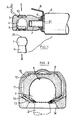
- Figure 8 est une vue en coupe d'une variante de la cage à rotule, la rotule et la bague étant enlevées.
- Figure 9 est une coupe selon la ligne IX-IX de la figure 8.
- Figures 10
et 11 sont des vues de dessous et en coupe de la cage, montrant une modalité particulière.
- Figure 1 is an elevational view in partial section of a joint according to the invention, before the establishment of the ball in its housing.
- Figure 2 is an enlarged section along line II-II of Figure 1, the ball being in place in its housing.
- Figure 3 is a side view of the ring.
- Figures 4 and 5 are views of one end of the ring, according to arrows IV and V in Figure 3.
- Figure 6 is a half-section similar to Figure 2, showing a variant.
- Figure 7 is a perspective view of one end of the ring.
- Figure 8 is a sectional view of a variant of the ball joint, the ball joint and the ring being removed.
- Figure 9 is a section along line IX-IX of Figure 8.
- Figures 10 and 11 are views from below and in section of the cage, showing a particular modality.
La figure 1 montre une articulation comprenant d'une part une rotule 1, portée par un tourillon 2, de type classique. Les formes et dimensions de ces rotules et tiges sont normalisées, notamment chez les constructeurs automobiles. L'articulation comprend, par ailleurs, une cage à rotule 3 qui présente une cavité 4, de forme hémisphérique, destinée à recevoir la rotule, et débouchant à l'extérieur par un canal 5, de même diamètre.Figure 1 shows a joint comprising on the one hand a ball joint 1, carried by a
La cage à rotule 3 est pourvue, par ailleurs, de moyens de fixation à un support, qui peut être un ressort à gaz 6, représenté en partie seulement sur la figure. Dans le cas représenté, ces moyens consistent en un trou taraudé 7, dont l'axe est perpendiculaire à celui du canal 5 et qui croise celui-ci au centre géométrique du logement hémisphérique 4, bien que cela ne soit pas indispensable. A la place du trou taraudé 7, on peut prévoir un logement pour auto-taraudage comme on le verra plus loin, ou encore un autre moyen de fixation. La référence 8 désigne une cosse de contact électrique, montée sur l'extrémité de la cage et immobilisée grâce à des pattes qui pénètrent dans des trous prévus autour du trou de fixation 7, et associée à un capuchon 9, destiné à protéger contre la corrosion le contact entre le ressort à gaz 6 et la cage à rotule, ainsi que le fond du ressort à gaz lui-même.The ball
La cage à rotule est en matière plastique moulée.The ball joint cage is made of molded plastic.
Une bague élastique 10, en forme de C, entoure partiellement la cage 3 rotule au voisinage du logement 4. Elle sera décrite avec plus de précision dans la suite.An
Le corps de la cage à rotule présente, à sa surface extérieure, dans la région du logement 4, une rainure 11. Cette rainure s'étend sur un peu plus de 180° de la périphérie de la cage, partant du débouché d'une fente 13, passant au-dessus du fond du logement 4, et revenant, de l'autre côté de la cage, s'arrêter au débouché de l'autre fente 13. Dans la partie sommitale, c'est-à-dire la partie opposée à l'ouverture du canal 5, le fond de la rainure est sensiblement plan, c'est-à-dire perpendiculaire à l'axe du canal 5, avec toutefois deux bossages 12, visibles aux figures 2 et 6, qui font saillie sur le fond de la rainure. A chacune de ses extrémités, la rainure 11 communique avec une fente 13, à section constante sur toute sa longueur qui traverse la paroi de la cage à rotule, pour déboucher dans le canal 5, au-dessous de la jonction de celui-ci avec le logement 4, à proximité d'une partie évasée 13, par laquelle ce canal 5 débouche vers l'extérieur. Une nervure 15, qui s'étend sur toute la longueur de la fente, est prévue sur la paroi interne de la fente, c'est-à-dire la paroi qui est du côté du logement 4. La direction générale de la fente 13 fait un angle d'environ 60° avec l'axe du logement 5, les deux fentes convergeant vers l'axe du canal 5, en direction de l'extérieur de la cage, c'est-à-dire à l'opposé du logement 4. La face interne de la fente 13, c'est-à-dire celle qui est la plus loin du logement 4, est sensiblement plane, et se prolonge jusqu'à la surface extérieure de la cage à rotule, en constituant la fin de la rainure 11. Deux bossages 16 et 17 sont prévus sur la face sommitale de la cage à rotule, c'est-à-dire du côté opposé au canal 4, l'un du côté des moyens de fixation 7, l'autre du côté opposé. Ces bossages sont adjacents à la rainure 11, et ils présentent, vers cette rainure, une face descendante, 18-19, inclinée à 45°.The body of the ball joint cage has, on its outer surface, in the region of the
Si on se reporte maintenant à la figure 3, qui représente la bague élastique 10 au repos, on constate qu'elle a une forme générale en C, symétrique, avec un corps 20 à peu près plat, mais pourvu à sa partie centrale d'une saillie 21, à forte convexité vers l'extérieur du C. Le corps 20 est prolongé par deux ailes en arc de cercle 22, qui font un angle d'environ 45° avec le corps 20, et s'étendent sur environ 90°. Ces ailes 22 se prolongent par des parties d'extrémités 23, qui sont sensiblement rectilignes, et convergent l'une vers l'autre.Referring now to Figure 3, which shows the
Les figures 4 et 5 montrent que, en plan, ces parties d'extrémités sont terminées par un angle rentrant 24, et les zones 25 qui sont de chaque côté de cet angle rentrant sont légèrement pliées vers l'intérieur.FIGS. 4 and 5 show that, in plan, these end portions are terminated by a
La figure 7 montre la même disposition, mais les angles ont été exagérés pour une meilleure compréhension. Si on regarde, en effet, ces parties d'extrémités en bout, comme indiqué à la figure 5, on constate qu'elles ne sont que légèrement pliées de façon à former une sorte de gouttière, dont la concavité est tournée vers l'intérieur de la bague, et cette gouttière est assez peu accusée, son angle au sommet est de l'ordre de 160°.Figure 7 shows the same layout, but the angles have been exaggerated for better understanding. If we look, in fact, at these end ends, as shown in Figure 5, we see that they are only slightly bent so as to form a sort of gutter, the concavity of which faces inward. of the ring, and this gutter is not very marked, its angle at the top is of the order of 160 °.
Si on se reporte de nouveau à la figure 2, on constate que la bague 10, quand elle est en place sur la cage à rotule 3, est en appui sur les deux points d'appui 12 et sur les deux nervures 15, qui la maintiennent par conséquent en tension, l'écart entre les parties d'extrémité 23 étant donc plus important qu'il ne l'est au repos. Il est important que cet écart soit supérieur à la dimension d'un méplat 26 qui est prévu, de façon classique, au sommet de la rotule 1. Si ce n'était pas le cas, en effet, il serait impossible d'introduire la rotule dans son logement, la bague étant en place, en une seule opération. Il s'agit, bien entendu, de la distance entre les parties d'extrémités 23, mesurées dans le plan médian de la bague, qui est aussi un plan médian pour la rotule. En effet, la forme en angle rentrant 24 des extrémités de parties 23 est adaptée à la forme circulaire de la rotule. Comme on peut le voir sur la figure 2, l'écart entre les parties 23 est également supérieur au diamètre du collet par lequel le tourillon 2 se raccorde à la rotule 1, ce qui permet un débattement angulaire du tourillon par rapport à la cage à rotule 3 de quelques degrés, sans qu'il y ait contact entre la tige 2 et la bague 10. Bien entendu, l'écartement entre les parties terminales 23 de la bague est largement inférieur au diamètre de la rotule 1, elle-même, sinon celle-ci pourrait s'échapper.If we refer again to Figure 2, we see that the
La bague 10 est constituée, comme on l'aura deviné, à partir d'une lame d'acier.The
A la figure 1, on a représenté en A la position d'un outil qu'on introduirait sous la partie fortement convexe 21 de la bague 10 en vue de soulever celle-ci pour dégager la rotule 1. On constate que l'opération est facilitée par les bossages 16 et 17 et leurs flancs inclinés 18-19. On peut observer que la partie fortement convexe 21 n'est pas absolument nécessaire pour introduire l'outil, il suffirait, par exemple, que les bords latéraux de la bague soient légèrement relevés vers le haut de la figure 1. Cette disposition, cependant, aurait le désavantage d'entraîner une augmentation de la raideur de la bague 10. La partie fortement convexe 21 a, au contraire, pour effet, d'augmenter de façon appréciable la flexibilité de cette bague, ce qui est un effet favorable.In Figure 1, there is shown in A the position of a tool that would be introduced under the highly
Les figures 6 et 7 sont relatives à l'autre modalité de la présente invention, à savoir celle où, au lieu de la rainure 15, on a prévu un bossage sur la bague. La figure 6 représente un dispositif en tous points conforme à celui de la figure 2, à la seule différence que la nervure 15 a été supprimée, et que, en contrepartie, la zone centrale de la partie d'extrémité 23 de la bague 10 présente un bossage 27, à convexité tournée vers l'intérieur de la bague 10, et qui vient en contact avec la face interne de la fente 13.Figures 6 and 7 relate to another mode of the present invention, namely that where, instead of the
Comme le montre mieux la figure 7, le bossage 27 est allongé le long de l'axe de la partie d'extrémité 23 de la bague. Cette disposition a pour effet d'augmenter la raideur de la bague dans cette région, où elle doit servir au verrouillage de la rotule. Comme on l'a dit plus haut, la figure 7 montre une vue volontairement déformée pour faciliter la compréhension.As best shown in Figure 7, the
Sur les figures 2 et 6, les fentes 13 sont représentées avec une forme rectiligne. Il est possible, tout en leur conservant une largeur sensiblement constante pour ne pas affaiblir la cage, de leur donner une forme incurvée qui peut faciliter l'introduction de la bague. Avantageusement, elles auront une forme d'arc de cercle dont le centre est dans le plan médian de la cage. Le démoulage de la cage s'effectuera alors par pivotement des deux moitiés du moule autour de ce centre.In Figures 2 and 6, the
La figure 8 montre une coupe d'une cage à rotule, dans laquelle la rotule elle-même et la bague sont supposées enlevées, mais qui est équipée par ailleurs d'une cosse électrique 8, fixée d'une manière différente de celle de la figure 1.Figure 8 shows a section through a ball joint cage, in which the ball joint itself and the ring are assumed to be removed, but which is also equipped with an
La cage à rotule, en effet, au lieu d'un trou taraudé 7, présente un trou pour auto-taraudage 28. Comme on le voit mieux à la figure 9, ce trou, à section de forme générale circulaire, présente dans sa paroi quatre larges rainures longitudinales 29, séparées par quatre nervures longitudinales 30. Selon la technique usuelle, lorsqu'on visse une pièce mâle filetée convenable dans un tel trou, les filets de cette pièce mâle viennent mordre dans les nervures 30, pour assurer la fixation. Dans le cas présent, la cosse électrique 8 comporte deux pattes 31, qui sont enfilées dans deux rainures 29 diamétralement opposées, dans faire saillie au-delà des nervures 30. Lorsque la pièce filetée mâle est insérée dans le trou 28, ses filets viennent mordre sur les pattes 31, mais moins fortement que dans les nervures 30. On assure ainsi un bon contact électrique dès le début de la mise en place de la pièce mâle, avec décapage éventuel des restants de peinture, maitères grasses, ou autres impuretés non conductrices qui pourraient subsister sur la pièce mâle.The ball joint cage, in fact, instead of a tapped
Dans le cas présent, cette pièce mâle constitue l'extrémité d'une tige de piston de ressort à gaz, non représentée. Le repère 32 se réfère à l'extrémité d'un tube de protection de cette tige de piston contre es contacts non désirés. Pour fixer de façon efficace ce tube 32 à la cage à rotule, celle-ci présente, à son extrémité, une partie cylindrique rétrécie 33, qui se termine sur une gorge 34, adacent à un épaulement 35 du corps de la cage à rotule. La gorge 34 et l'épaulement 35 servent respectivement de zones d'accrochage et de butées à un disque 36, en matière souple telle que du caoutchouc, qui est enfilé d'une part sur la cage à rotule et, d'autre part, dans le tube 32. On assure ainsi une fixation efficace, durable et étanche. Ce mode de fixation est le même que celui qui est employé pour le joint 9, visible à la figure 1, et qui sert à obtenir directement l'étanchéité, et la protection contre la corrosion, entre la cage à rotule et le corps 6 d'un ressort à gaz.In the present case, this male part constitutes the end of a gas spring piston rod, not shown.
On observera que le fond du trou 28 avance jusqu'à proximité de la cavité 4 qui sert de logement à la rotule, si bien qu'il subsiste seulement un voile de faible épaisseur entre cette cavité et le fond du trou 28. Cette disposition intentionnelle a le résultat suivant : attendu que le ressort à gaz exerce en permanence sur la cage à rotule une action qui tend à pousser la paroi de la cavité contre la rotule, dans une direction perpendiculaire à l'axe du canal 5, la matière plastique dont est faite la cage à rotule se déforme pour épouser celle de la rotule. On obtient ainsi un contact permanent et fixe entre la rotule et sa cage, même si la cavité a été prévue avec un diamètre légèrement supérieur au diamètre nominal de la rotule, de façon à compenser les éventuelles irrégularités dues à la présence de peinture, notamment.It will be observed that the bottom of the
On conçoit qu'on pourrait supprimer le voile et obtenir un résultat analogue en déformant seulement les bords de la zone où le trou 28 déboucherait dans la cavité 4, il y a cependant lieu de noter que, dans cette situation, la protection de l'extrémité du ressort à gaz contre la corrosion serait moins bien assurée.It is understood that one could remove the veil and obtain a similar result by deforming only the edges of the zone where the
La figure 11 représente une cage à rotule qui est très semblable à celle de la figure 6, à part la présence, dans le canal 5, et la partie adjacente de la cavité 4, d'une série de nervures 37, parallèles à l'axe du canal 5. Ces nervures 37, dont la forme est mieux visible sur la figure 10, servent à obtenir un résultat analogue à celui qui est procuré par le voile situé au fond du trou 28, et dont a parlé plus haut, à savoir compenser les variations inévitables du diamètre de la rotule. Les nervures 37 ont une autre utilité, car les vides qui se trouvent entre ces nervures peuvent servir de réserves de matières lubrifiantes. On observera sur la figure 10, qu'une partie 38 de la périphérie du canal 5 ne comporte pas de nervures, mais présente au contraire une surface lisse. Il s'agit de la partie qui est normalement appuyée contre la rotule par l'effet de la force permanente du ressort à gaz. On observera que les deux effets produits par les rainures, compensation des irrégularités de diamètre et formation d'une réserve de lubrifiant,peuvent être obtenus avec d'autres types d'irrégularités de surface. On peut prévoir par exemple des rainures assez nombreuses et à bords lisses, toujours dirigées parallèlement à l'axe du canal 5. On peut également donner à la cavité 4 et/ou au canal 5 une forme polygonale. Selon le rapport des duretés de la matière dont est faite la cage et de la matière dont est faite la rotule, l'importance des irrégularités sera plus ou moins grande.FIG. 11 represents a ball joint cage which is very similar to that of FIG. 6, except for the presence, in the
Claims (17)
caractérisée en ce que, lorsque la rotule est absente, la bague, d'une part, exerce sur la cage une force de pression à peu près parallèle à l'axe du canal en deux points (12) situés de part et d'autre de celui-ci et écartés de cet axe, et, d'autre part, exerce d'autre forces de pression sur la face interne de la fente (13) par l'intermédiaire de deux bossages (27) à convexité tournée vers l'intérieur de la bague, et formés sur celle-ci, ou d'une saillie (15) prévue sur ladite face interne de la fente, et en ce que, lorsque la rotule est dans la cavité, le tourillon étant coaxial au canal, la bague n'est en contact ni avec la rotule (1), ni avec le tourillon (2), et occupe la même position que lorsque la rotule est absente.1. Removable ball joint, comprising on the one hand a spherical ball joint (1), integral with a pin (2) and, on the other hand, a cage (3) having a cavity (4) adapted to receive the ball joint , connected to the outside by a channel (5) to allow the introduction of the ball joint, said cage being moreover provided with means (7) for fixing to a support, and with an elastic ring (10), in its C-shaped assembly, the body of which surrounds said cage, and the ends of which (23) penetrate into two slots (13) of the cage, these slots being arranged on either side of said channel and opening into it for allow the ends of the ring to protrude inside the channel and retain the ball in the cavity, these slots being oblique with respect to the axes of the channel, and moving away from the center of the cavity while approaching said axis,
characterized in that, when the ball joint is absent, the ring, on the one hand, exerts on the cage a pressure force roughly parallel to the axis of the channel at two points (12) located on either side from the latter and spaced from this axis, and, on the other hand, exerts other pressure forces on the internal face of the slot (13) by means of two bosses (27) with convexity turned towards the inside of the ring, and formed thereon, or a projection (15) provided on said internal face of the slot, and in that, when the ball joint is in the cavity, the pin being coaxial with the channel, the ring is in contact neither with the ball joint (1), nor with the pin (2), and occupies the same position as when the ball joint is absent.
Priority Applications (1)
| Application Number | Priority Date | Filing Date | Title |
|---|---|---|---|
| AT88400653T ATE58419T1 (en) | 1987-04-01 | 1988-03-18 | REMOVABLE BALL JOINT. |
Applications Claiming Priority (2)
| Application Number | Priority Date | Filing Date | Title |
|---|---|---|---|
| FR8704547A FR2613440B1 (en) | 1987-04-01 | 1987-04-01 | REMOVABLE JOINT WITH BALL JOINT |
| FR8704547 | 1987-04-01 |
Related Child Applications (4)
| Application Number | Title | Priority Date | Filing Date |
|---|---|---|---|
| EP19890114152 Division EP0347949A3 (en) | 1987-04-01 | 1988-03-18 | Removable ball joint |
| EP19890114149 Division EP0344822A3 (en) | 1987-04-01 | 1988-03-18 | Removable ball joint |
| EP89114152.5 Division-Into | 1988-03-18 | ||
| EP89114149.1 Division-Into | 1988-03-18 |
Publications (2)
| Publication Number | Publication Date |
|---|---|
| EP0287411A1 true EP0287411A1 (en) | 1988-10-19 |
| EP0287411B1 EP0287411B1 (en) | 1990-11-14 |
Family
ID=9349662
Family Applications (3)
| Application Number | Title | Priority Date | Filing Date |
|---|---|---|---|
| EP19890114152 Withdrawn EP0347949A3 (en) | 1987-04-01 | 1988-03-18 | Removable ball joint |
| EP88400653A Expired - Lifetime EP0287411B1 (en) | 1987-04-01 | 1988-03-18 | Removable ball joint |
| EP19890114149 Withdrawn EP0344822A3 (en) | 1987-04-01 | 1988-03-18 | Removable ball joint |
Family Applications Before (1)
| Application Number | Title | Priority Date | Filing Date |
|---|---|---|---|
| EP19890114152 Withdrawn EP0347949A3 (en) | 1987-04-01 | 1988-03-18 | Removable ball joint |
Family Applications After (1)
| Application Number | Title | Priority Date | Filing Date |
|---|---|---|---|
| EP19890114149 Withdrawn EP0344822A3 (en) | 1987-04-01 | 1988-03-18 | Removable ball joint |
Country Status (7)
| Country | Link |
|---|---|
| US (1) | US4895472A (en) |
| EP (3) | EP0347949A3 (en) |
| AT (1) | ATE58419T1 (en) |
| CA (1) | CA1295846C (en) |
| DE (1) | DE3861046D1 (en) |
| ES (1) | ES2019694B3 (en) |
| FR (1) | FR2613440B1 (en) |
Families Citing this family (20)
| Publication number | Priority date | Publication date | Assignee | Title |
|---|---|---|---|---|
| FR2691415B1 (en) * | 1992-05-25 | 1998-06-12 | Valeo Vision | BALL JOINT MOUNTING DEVICE AND INTERMEDIATE ELEMENT, IN PARTICULAR FOR A MOTOR VEHICLE PROJECTOR REFLECTOR. |
| WO1995033139A1 (en) * | 1994-05-31 | 1995-12-07 | Itt Automotive Electrical Systems, Inc. | Integral tophat linkball |
| DE19503499C1 (en) * | 1995-02-03 | 1996-03-28 | Fichtel & Sachs Ag | Link eyelet for shock absorber |
| DE29617843U1 (en) * | 1996-10-14 | 1998-02-12 | Springfix-Befestigungstechnik GmbH, 73084 Salach | Ball-joint connection with effective shielding against external influences |
| US6065265A (en) * | 1997-05-01 | 2000-05-23 | Newtec Building Products Inc. | Corner and end block for interlocking building block system |
| DE19752076A1 (en) * | 1997-11-25 | 1999-05-27 | Schaeffler Waelzlager Ohg | Piston rod fastening on piston of master cylinder |
| FR2782758B1 (en) * | 1998-09-02 | 2000-09-29 | Skf France | ROLLING BEARING |
| DE10041265C5 (en) * | 2000-08-23 | 2006-11-23 | Stabilus Gmbh | Ball joint assembly for a piston-cylinder unit |
| US7172237B2 (en) * | 2003-11-14 | 2007-02-06 | Avm Industries | High rotation angle for gas spring connection |
| DE102006020103B4 (en) * | 2006-04-29 | 2016-02-11 | Stabilus Gmbh | ball joint |
| DE102007062484B3 (en) * | 2007-12-20 | 2009-04-30 | Gardner Denver Deutschland Gmbh | Industrial diecast piece comprises a first side, a second side having a lateral face, an aperture opening, which opens at the second side and penetrates the second lateral face, a housing body, and projections |
| DE102008003463A1 (en) * | 2008-01-08 | 2009-07-09 | Trw Automotive Gmbh | Method for producing a bearing shell assembly, and bearing shell assembly for a ball joint |
| US7993070B2 (en) * | 2008-08-20 | 2011-08-09 | Stabilus Gmbh | Quick disconnect ball socket end fitting |
| DE102010052335B3 (en) * | 2010-11-25 | 2012-03-08 | Bayerische Motoren Werke Aktiengesellschaft | Removal tool for gas pressure spring disassembly from motor car, has arm side support portion engaging with engaging element, while support portion at clamping element side is provided facing engagement location of engagement element |
| DE102010054030B4 (en) * | 2010-12-09 | 2013-03-21 | Rsn Sihn Gmbh | Tool for disassembling a ball joint |
| KR102036851B1 (en) * | 2012-07-12 | 2019-10-25 | 보르그워너 인코퍼레이티드 | Rod end tensioner and self adjusting rod end |
| EP3080465B1 (en) * | 2013-12-12 | 2018-01-31 | Kongsberg Automotive AB | Ball joint connector |
| DE102019123934B3 (en) | 2019-09-06 | 2020-12-10 | Peter Hödl | Foldable wall structure for expanding the interior space of transportable bodies, especially mobile homes |
| CN112922955B (en) * | 2021-03-21 | 2022-11-22 | 重庆峰聂机械有限公司 | Vertical assembling tool for automobile engine ball head assembly |
| CN115447673B (en) * | 2022-08-30 | 2023-06-20 | 东风柳州汽车有限公司 | Back door stay bar assembly, gas stay bar and automobile |
Citations (3)
| Publication number | Priority date | Publication date | Assignee | Title |
|---|---|---|---|---|
| GB323976A (en) * | 1929-03-21 | 1930-01-16 | Edwin Bolton | Ball linkage joints |
| FR2399578A1 (en) * | 1977-08-06 | 1979-03-02 | Stabilus Gmbh | ELECTRIC CURRENT TELESCOPIC SPRING |
| FR2439901A1 (en) * | 1978-10-23 | 1980-05-23 | Gas Spring Corp | BOWL ASSEMBLY FOR BALL JOINT |
Family Cites Families (8)
| Publication number | Priority date | Publication date | Assignee | Title |
|---|---|---|---|---|
| FR1012635A (en) * | 1950-01-09 | 1952-07-15 | Ehrenreich & Cie A | Ball joint for all kinds of uses and in particular for steering linkages |
| FR2238859A1 (en) * | 1973-07-27 | 1975-02-21 | Automotive Prod Co Ltd | Ball joint for steering mechanism of a vehicle - has a plastic insert to hold the ball retained by deforming socket |
| FR2345614A2 (en) * | 1976-03-25 | 1977-10-21 | Itw De France | KNEE JOINT BOWL |
| DE7736254U1 (en) * | 1977-11-26 | 1978-03-23 | Dr.Ing.H.C. F. Porsche Ag, 7000 Stuttgart | SWITCH FOR INTERIOR LIGHTS OF MOTOR VEHICLES |
| DE2802465A1 (en) * | 1978-01-20 | 1979-07-26 | United Carr Gmbh | Fibre reinforced plastics self locking nut - has smooth bore with radial slots for forming thread during installation |
| US4591276A (en) * | 1984-01-14 | 1986-05-27 | Skf Gmbh | Radial ball-and-socket bearing |
| JPS6138315U (en) * | 1984-08-13 | 1986-03-10 | 株式会社 ニフコ | ball joint |
| DE3602917C1 (en) * | 1986-01-31 | 1987-07-30 | Trw Ehrenreich Gmbh | Ball joint |
-
1987
- 1987-04-01 FR FR8704547A patent/FR2613440B1/en not_active Expired
-
1988
- 1988-03-18 ES ES88400653T patent/ES2019694B3/en not_active Expired - Lifetime
- 1988-03-18 DE DE8888400653T patent/DE3861046D1/en not_active Expired - Fee Related
- 1988-03-18 EP EP19890114152 patent/EP0347949A3/en not_active Withdrawn
- 1988-03-18 US US07/169,945 patent/US4895472A/en not_active Expired - Lifetime
- 1988-03-18 EP EP88400653A patent/EP0287411B1/en not_active Expired - Lifetime
- 1988-03-18 AT AT88400653T patent/ATE58419T1/en not_active IP Right Cessation
- 1988-03-18 EP EP19890114149 patent/EP0344822A3/en not_active Withdrawn
- 1988-03-23 CA CA000562226A patent/CA1295846C/en not_active Expired - Fee Related
Patent Citations (3)
| Publication number | Priority date | Publication date | Assignee | Title |
|---|---|---|---|---|
| GB323976A (en) * | 1929-03-21 | 1930-01-16 | Edwin Bolton | Ball linkage joints |
| FR2399578A1 (en) * | 1977-08-06 | 1979-03-02 | Stabilus Gmbh | ELECTRIC CURRENT TELESCOPIC SPRING |
| FR2439901A1 (en) * | 1978-10-23 | 1980-05-23 | Gas Spring Corp | BOWL ASSEMBLY FOR BALL JOINT |
Also Published As
| Publication number | Publication date |
|---|---|
| EP0287411B1 (en) | 1990-11-14 |
| DE3861046D1 (en) | 1990-12-20 |
| CA1295846C (en) | 1992-02-18 |
| EP0344822A3 (en) | 1990-12-05 |
| EP0347949A2 (en) | 1989-12-27 |
| EP0344822A2 (en) | 1989-12-06 |
| FR2613440B1 (en) | 1989-07-21 |
| ATE58419T1 (en) | 1990-11-15 |
| US4895472A (en) | 1990-01-23 |
| FR2613440A1 (en) | 1988-10-07 |
| ES2019694B3 (en) | 1991-07-01 |
| EP0347949A3 (en) | 1990-12-05 |
Similar Documents
| Publication | Publication Date | Title |
|---|---|---|
| EP0287411B1 (en) | Removable ball joint | |
| EP0627346B1 (en) | Windscreen wiper with a pivot between a crank and a link rod | |
| EP0311498B1 (en) | Fastening systems having nuts secured within cages | |
| FR2758662A1 (en) | MOBILE CONTACT COAXIAL ELECTRIC CONNECTOR ELEMENT AND COAXIAL ELECTRIC CONNECTOR INCLUDING SUCH A CONNECTOR ELEMENT | |
| FR2624452A1 (en) | FIXING AND ARTICULATING MEMBER, IN PARTICULAR FOR A DEVICE FOR ADJUSTING AN OPTICAL ELEMENT, IN PARTICULAR FOR A MOTOR VEHICLE PROJECTOR | |
| FR3050477B1 (en) | CLUTCH DEVICE, VEHICLE HINGE INCLUDING SUCH A CLAMPING DEVICE AND METHOD OF USING SUCH CLAMPING DEVICE | |
| EP0312438B1 (en) | Self stripping connector for electrical conductor | |
| WO1999045287A1 (en) | Mechanical transmission member and its application to a mechanical constant velocity joint | |
| EP0356329B2 (en) | Tapping assembly for a secondary cable to be connected to a main uninterrupted cable | |
| EP0379392A1 (en) | Ball joint | |
| EP0561704B1 (en) | Axial rolling bearing for a vehicle suspension and its mounting method | |
| FR2720866A1 (en) | Clamper device forming a rear connector connector. | |
| FR2744502A1 (en) | BALL HOMOCINETIC TRANSMISSION SEAL | |
| EP0584018B1 (en) | Windscreen wiper with improved mounting head | |
| FR2633443A1 (en) | ELECTRICAL CONTACTOR FOR PNEUMATIC BRAKE SERVOMOTOR | |
| EP0797718B1 (en) | Temporary door stop for a motor vehicle door hinge, and device for attaching same | |
| FR2691767A1 (en) | Flexible rubber ball joint for trailing suspension arms - is made as two-part metallic shell with enlarged borders, distinct from inner tube and forced over it | |
| WO2008145878A1 (en) | Accessory of the backshell type for connector | |
| EP0429336A1 (en) | Reservoir cap, in particular fuel tank cap for motor vehicle | |
| FR2478379A1 (en) | Anchorage for vehicle tilting aerial - is insulated block with cavities for hinge pin and combined securing and connecting bolt | |
| EP1721795B1 (en) | Device and method for fixing a wiper mechanism on a vehicle body and automotive vehicle with such a device | |
| FR2715512A1 (en) | Connector for coaxial cable. | |
| WO2020115414A1 (en) | Protective bellows and transmission joint provided with such a bellows | |
| FR2588628A1 (en) | Cap intended for retaining the ball of an electric motor bearing, bearing and electric motor equipped with such a cap | |
| EP0884806B1 (en) | Electrical connector with improved contact security |
Legal Events
| Date | Code | Title | Description |
|---|---|---|---|
| PUAI | Public reference made under article 153(3) epc to a published international application that has entered the european phase |
Free format text: ORIGINAL CODE: 0009012 |
|
| AK | Designated contracting states |
Kind code of ref document: A1 Designated state(s): AT BE CH DE ES FR GB IT LI LU NL SE |
|
| 17P | Request for examination filed |
Effective date: 19881017 |
|
| 17Q | First examination report despatched |
Effective date: 19890425 |
|
| GRAA | (expected) grant |
Free format text: ORIGINAL CODE: 0009210 |
|
| AK | Designated contracting states |
Kind code of ref document: B1 Designated state(s): AT BE CH DE ES FR GB IT LI LU NL SE |
|
| REF | Corresponds to: |
Ref document number: 58419 Country of ref document: AT Date of ref document: 19901115 Kind code of ref document: T |
|
| GBT | Gb: translation of ep patent filed (gb section 77(6)(a)/1977) | ||
| REF | Corresponds to: |
Ref document number: 3861046 Country of ref document: DE Date of ref document: 19901220 |
|
| ITF | It: translation for a ep patent filed | ||
| PLBE | No opposition filed within time limit |
Free format text: ORIGINAL CODE: 0009261 |
|
| STAA | Information on the status of an ep patent application or granted ep patent |
Free format text: STATUS: NO OPPOSITION FILED WITHIN TIME LIMIT |
|
| 26N | No opposition filed | ||
| PGFP | Annual fee paid to national office [announced via postgrant information from national office to epo] |
Ref country code: AT Payment date: 19920311 Year of fee payment: 5 |
|
| PGFP | Annual fee paid to national office [announced via postgrant information from national office to epo] |
Ref country code: SE Payment date: 19920319 Year of fee payment: 5 Ref country code: LU Payment date: 19920319 Year of fee payment: 5 |
|
| PGFP | Annual fee paid to national office [announced via postgrant information from national office to epo] |
Ref country code: CH Payment date: 19920326 Year of fee payment: 5 |
|
| ITTA | It: last paid annual fee | ||
| PGFP | Annual fee paid to national office [announced via postgrant information from national office to epo] |
Ref country code: NL Payment date: 19920331 Year of fee payment: 5 |
|
| PGFP | Annual fee paid to national office [announced via postgrant information from national office to epo] |
Ref country code: BE Payment date: 19920512 Year of fee payment: 5 |
|
| EPTA | Lu: last paid annual fee | ||
| PG25 | Lapsed in a contracting state [announced via postgrant information from national office to epo] |
Ref country code: LU Free format text: LAPSE BECAUSE OF NON-PAYMENT OF DUE FEES Effective date: 19930318 Ref country code: AT Effective date: 19930318 |
|
| PG25 | Lapsed in a contracting state [announced via postgrant information from national office to epo] |
Ref country code: SE Effective date: 19930319 |
|
| PG25 | Lapsed in a contracting state [announced via postgrant information from national office to epo] |
Ref country code: LI Effective date: 19930331 Ref country code: CH Effective date: 19930331 Ref country code: BE Effective date: 19930331 |
|
| BERE | Be: lapsed |
Owner name: AIRAX Effective date: 19930331 |
|
| PG25 | Lapsed in a contracting state [announced via postgrant information from national office to epo] |
Ref country code: NL Effective date: 19931001 |
|
| NLV4 | Nl: lapsed or anulled due to non-payment of the annual fee | ||
| REG | Reference to a national code |
Ref country code: CH Ref legal event code: PL |
|
| EUG | Se: european patent has lapsed |
Ref document number: 88400653.7 Effective date: 19931008 |
|
| REG | Reference to a national code |
Ref country code: GB Ref legal event code: IF02 |
|
| PGFP | Annual fee paid to national office [announced via postgrant information from national office to epo] |
Ref country code: FR Payment date: 20050308 Year of fee payment: 18 |
|
| PGFP | Annual fee paid to national office [announced via postgrant information from national office to epo] |
Ref country code: DE Payment date: 20050310 Year of fee payment: 18 |
|
| PGFP | Annual fee paid to national office [announced via postgrant information from national office to epo] |
Ref country code: GB Payment date: 20050316 Year of fee payment: 18 |
|
| PGFP | Annual fee paid to national office [announced via postgrant information from national office to epo] |
Ref country code: ES Payment date: 20050425 Year of fee payment: 18 |
|
| PG25 | Lapsed in a contracting state [announced via postgrant information from national office to epo] |
Ref country code: GB Free format text: LAPSE BECAUSE OF NON-PAYMENT OF DUE FEES Effective date: 20060318 |
|
| PG25 | Lapsed in a contracting state [announced via postgrant information from national office to epo] |
Ref country code: ES Free format text: LAPSE BECAUSE OF NON-PAYMENT OF DUE FEES Effective date: 20060321 |
|
| PGFP | Annual fee paid to national office [announced via postgrant information from national office to epo] |
Ref country code: IT Payment date: 20060331 Year of fee payment: 19 |
|
| PG25 | Lapsed in a contracting state [announced via postgrant information from national office to epo] |
Ref country code: DE Free format text: LAPSE BECAUSE OF NON-PAYMENT OF DUE FEES Effective date: 20061003 |
|
| GBPC | Gb: european patent ceased through non-payment of renewal fee |
Effective date: 20060318 |
|
| REG | Reference to a national code |
Ref country code: FR Ref legal event code: ST Effective date: 20061130 |
|
| REG | Reference to a national code |
Ref country code: ES Ref legal event code: FD2A Effective date: 20060321 |
|
| PG25 | Lapsed in a contracting state [announced via postgrant information from national office to epo] |
Ref country code: FR Free format text: LAPSE BECAUSE OF NON-PAYMENT OF DUE FEES Effective date: 20060331 |
|
| PG25 | Lapsed in a contracting state [announced via postgrant information from national office to epo] |
Ref country code: IT Free format text: LAPSE BECAUSE OF NON-PAYMENT OF DUE FEES Effective date: 20070318 |