EP0287401A2 - Richten von bearbeitungsfähigem Bandmaterial - Google Patents
Richten von bearbeitungsfähigem Bandmaterial Download PDFInfo
- Publication number
- EP0287401A2 EP0287401A2 EP88303458A EP88303458A EP0287401A2 EP 0287401 A2 EP0287401 A2 EP 0287401A2 EP 88303458 A EP88303458 A EP 88303458A EP 88303458 A EP88303458 A EP 88303458A EP 0287401 A2 EP0287401 A2 EP 0287401A2
- Authority
- EP
- European Patent Office
- Prior art keywords
- strip
- rollers
- dressing
- dressed
- pair
- Prior art date
- Legal status (The legal status is an assumption and is not a legal conclusion. Google has not performed a legal analysis and makes no representation as to the accuracy of the status listed.)
- Withdrawn
Links
Images


Classifications
-
- B—PERFORMING OPERATIONS; TRANSPORTING
- B21—MECHANICAL METAL-WORKING WITHOUT ESSENTIALLY REMOVING MATERIAL; PUNCHING METAL
- B21D—WORKING OR PROCESSING OF SHEET METAL OR METAL TUBES, RODS OR PROFILES WITHOUT ESSENTIALLY REMOVING MATERIAL; PUNCHING METAL
- B21D19/00—Flanging or other edge treatment, e.g. of tubes
- B21D19/005—Edge deburring or smoothing
Definitions
- the present invention relates to apparatus for dressing workable strip material, comprising a pair of dressing rollers mounted for rotation and each having surface formations for engaging a respective surface of a strip passing between the rollers being sufficiently closely spaced to bear on and dress surfaces of a strip as it passes.
- edges of the strip must be dressed, for instance to give the edges a desired profile.
- Fig. 1 Apparatus which has previously been proposed for dressing the edges of strop steel is shown schematically in Fig. 1.
- steel strip 10 is drawn from a coil 12 through guide rollers 14 and moves in the direction indicated by the arrow 16, passing between dressing rollers 18 (only one of which is visible in Fig. 1), and a rolling mill 20, before passing through further guide rollers 22 and being re-coiled at 24.
- the dressing rollers 18 are placed on either side of the strip 10 and are rotatable about respective axes generally perpendicular to the direction 16. Each roller 18 has a circumferential groove in which the edge of the strip 10 is located. The rollers 18 are sufficiently close to one another that force is required to drive the strip 10 between the rollers 18. This force causes the grooves on the rollers 18 to dress the edges to give them a desired profile.
- the driving force required is provided by the rolling mill 20. This comprises upper and lower rollers 26 between which the strip 10 is tightly squeezed in order to give the rollers 26 sufficient grip to pull the strip 10 between the rollers 18. In order to provide the required edge-dressing, the rollers 26 must tightly grip the strip 10. Thus, hot-rolled steel strip may be reworked by the mill 20 so that the coil 24 more closely resembles cold-rolled steel.
- the coil 24 can be removed and taken to a cutting machine.
- a suitable cutting machine would repeatedly unravel a length of strip from the coil 24, measure the unravelled length and cut the measured length to produce dressed, cut-to-length steel strips.
- Apparatus according to the present invention is characterised by comprising at least one further pair of dressing rollers as aforesaid, and in that the rollers of each pair are more closely spaced than the rollers of the preceeding pair.
- the rollers are so located as to dress the edges of a strip.
- the apparatus may comprise pinch rollers for driving strip material between the dressing rollers.
- the apparatus may comprise drive rollers for driving strip material between the dressing rollers, there being sufficient number of drive rollers to provide between them the force required to drive the strip material without any single drive roller applying sufficient force to the surface of the strip to change surface properties of the strip.
- the apparatus includes further processing means for forming dressed strip into a finished article.
- There may be a region in which the strip is unsupported and hangs freely, the said region being between the dressing rollers and the further processing means whereby dressed strip may be supplied continuously to the said region and drawn discontinuously from the said region, and whereby strip being dressed is isolated by movement of strip within the said region from discontinuous forces being applied to strip being drawn from the said region.
- the flattening means may comprise a series of rollers between which dressed strip passes, and which define a wave-like path for the strip, the magnitude of the wave decreasing in the direction of movement of the strip.
- the apparatus preferably includes pre-heating means operable to pre-heat and soften the edges of the strip material prior to passing between a pair of dressing rollers.
- the pre-heating means may comprise an induction coil for inducing eddy currents in metal strip material, thereby heating the material.
- the or each coil preferably comprises a current-carrying bar which follows a wave-like path along the edge of the strip, adjacent peaks of the wave being located respectively above and below the material, the troughs of the wave extending around the edge of the material of connect adjacent peaks.
- the apparatus preferably comprises at least two pairs of dressing rollers located before the pre-heating means, and at least one pair of dressing rollers located after the pre-heating means.
- the apparatus may comprise a chamber containing an inert atmosphere through which strip passes after being heated and dressed at elevated temperature.
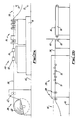
- Figs. 2A and 2B show a line for the production of dressed, cut-to-length steel, and including apparatus 30 for dressing the strip, comprising two pairs of dressing rollers 32,34 (only one roller of each pair being visible).
- the rollers 32,34 of each pair are mounted for rotation and each has surface formations, in the form of grooves, for engaging a respective edge of a strip 36 passing between the rollers 32,34.
- the rollers 32,34 are so located that the strip 36 passes firstly between the first pair 32 of rollers and then between the second pair 34.
- the rollers of each pair are sufficiently closely spaced that the grooves bear on and dress the edges of the strip 36 as it passes, and the rollers 34 of the second pair are are more closely spaced than the rollers 32 of the first pair.
- the strip 36 is supplied from a de-coil unit 38 in which a coil 40 of hot-rolled steel is supported. Exit rollers 42 guide the strip 36 so that it always leaves the de-coil unit 38 at the same height above the ground 44.
- the strip 36 then passes along a generally horizontal path to the dressing apparatus 30.
- the strip 36 first passes between the first pair of rollers 32 and while doing so, the edges of the strip 36 are located in circumferential grooves on the rollers 32.
- the rollers 32 dress the edges in the same way as the rollers 18 of Fig. 1, except that dressing is provided in two stages in the apparatus 30.
- the rollers 32 provide only an initial dressing; dressing is completed by the second pair of rollers 34.
- the general form of the dressing rollers is shown in Fig. 3.
- the roller 46 (which may be one of the rollers 32 or 34) has two circumferential grooves 48,50.
- the edge of the strip 16 is shown in position for dressing in the groove 48.
- the groove 50 is used to dress strip of different thickness.
- the roller 46 is removed from its mounting and inverted so that the groove 50 is at the height of the strip 36 leaving the exit rollers 42.
- both grooves may be intended for use with the same thickness of strip, but designed to give different degrees of dressing or different edge profiles.
- rollers 34 are more closely spaced than the rollers 32. This is shown in Fig. 4, which is both highly schematic and highly exaggerated. It can be seen that the gap between the second rollers 34 is narrower than the gap between the rollers 32 for strip moving in the direction of the arrow 52 so that dressed strip leaving the rollers 32 is further dressed by the rollers 34.
- the force required to draw the strip 36 through the dressing apparatus 30 is provided by a pinch roller unit 54.
- Pinch roller units apply only very light pressure to the surface of strip being driven and this force is insufficient to rework the surface, so that hot-rolled properties of the strip 36 will be retained as it passes through the unit 54.
- the strip 36 Upon leaving the unit 54, the strip 36 passes through a hanging zone 56 and a flattener 58 before reaching a cutting station at which a guillotine blade 60 can cut against an anvil 62 to produce cut lengths 64 which are conveyed away by a conveyor 66.
- a guillotine blade 60 In order to allow the guillotine 60 to produce accurately cut lengths 64, strip is drawn from the region 56 in a discontinuous (or stop-start) fashion by drive rollers 68. This allows the strip 36 to be accurately positioned between the guillotine 60 and anvil 62 and cut while stationary.
- the flattener 58 ensures that any residual curvature in the strip 36 is removed.
- the flattener 58 includes a large number of rollers 70 between which the strip 36 must pass.
- the rollers 70 define a wave-like path. The magnitude of the wave is initially high, and decreases steadily through the flattener 58. That is, the path is initially undulates very strongly, so that the strip 36 is flexed to a considerable degree first in one sense and then in the opposite sense. As the strip 36 progresses, the flexing reduces in magnitude and finally ceases. This alternate flexing in opposite senses relieves stresses in the strip so that it arrives at the guillotine 60 in a substantially flat condition.
- the region 56 provides a reservoir of strip 36 between the output of the pinch roller unit 54 and the input of the flattener 58. This is provided for the following reason. It is found that the quality of the edge-dressing is increased if movement through the dressing apparatus 30 is continuous. Conversely, as described above, movement at the guillotine 60 is required to be discontinuous.
- the reservoir of strip 36 in the region 56 can be taken up by the flattener 58, or increased by the pinch rollers 54 as required to make a smooth transition between the continuous and the discontinuous motions.
- the hanging loop of strip 36 isolates the strip passing through the dressing unit 30 from the discontinuous forces being applied by the rollers 68.
- the speed of strip through the dressing apparatus 30 is set to equal the average speed o movement through the guillotine 60 so that the loop hanging in the region 56 will oscillate up and down but not, on average, be shortened or lengthened. If any mismatch between the speeds occurs, the loop will steadily shorten or lengthen. Shortening or lengthening is monitored by photo-electric beams and sensors 72 which monitor the position of the lowest point of the loop. If the lower beam is broken, the loop is too long and the speed through the dressing apparatus is too high. Dressing can therefore be temporarily stopped or the speed reduced, or the speed of feed to the guillotine 60 can be increased.
- the dressing unit 30 and pinch roller unit 54 may be mounted on a plinth 74 so that the height of the strip path through these units is higher than the height of the path through the flattener 58 and guillotine 60.
- Fig. 5 shows a pre-heating device which can be used in the line described above, in order to pre-heat the edges of the strip 36 before it enters the dressing apparatus 30.
- the pre-heating apparatus 80 comprises two induction coils 82,84 to which alternating electric current can be supplied through connectors 85.
- each coil 82,84 is made from relatively thick metal bar, and is self-supporting.
- the bars follow a wave-like path along respective edges of the strip 36. That is, when viewed in plan, the path of each bar has crests 86 in which the bar is between the edges of the strip 36, and troughs 88 in which the bar is beyond the edges of the strip 36. Adjacent creates 86 on each bar project respectively above and below the strip 36.
- the trough 88 between each neighbouring pair of crests 86 passes around the edge of the strip 36 to connect the crests 86.
- each coil 82,84 consists of two crests 86 above the strip 36, two crests 86 below the strip 36, and the requisite number of troughs to connect these crests and to connect the ends of the bar to the connectors 85.
- alternating current at between 600 Hz and 10 KHz for instance, is supplied to the induction coils 83,84.
- the coils generate alternating magnetic fields locally in the region of the strip edges.
- the fields in turn create eddy currents within the strip 36 and cause the edges to become heated.
- the length of the coils 82,84, the speed of movement of the strip 36 and the energizing currents are set to cause the edges to be heated to a plastic state before entering the dressing apparatus 30.
- the plastic state of the edges further reduces the force required to draw the strip 36 through the dressing rollers 32, and so further reduces the vertical forces to be applied by the pinch roller unit 54.
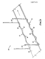
- Fig. 6 shows an alternative line for dressing strip which is supplied from a de-coiling unit, from the left hand side of the drawing, and leaves the apparatus from the right hand side of the drawing to be re-coiled.
- the strip first passes through to de-burring and guide rollers 100 before entering a flattener unit 102 which flattens the strip in the same manner as the unit 58 in Fig. 2B.
- the next station 104 comprises welding, cutting and clamping apparatus which is used each time a new coil is put in the de-coiling apparatus to weld the trailing edge of the last coil to the leading edge of the new coil.
- the cutting apparatus is used to trim the trailing and leading edges before welding.
- a similar station may be provided downstream of the apparatus, to cut out welds formed by the station 104, to ensure that welded strip is not re-coiled.
- the strip After leaving the welding station 104, the strip passes through two pairs of dressing rollers 106 arranged like the rollers 32,34 of Fig. 2A. Pinch rollers 108 provide the necessary drive, without re-working the strip surface. The strip is then further dressed by a further two pairs of dressing rollers 110 following which is a further set of pinch rollers 112.
- the strip Downstream of the pinch rollers 112, the strip passes through a heating station 114 which incorporates heating coils 116 like those shown in Fig. 5, arranged to heat the two edges of the strip to a temperature which is preferably in the region of 550 degrees centigrade to 600 degrees centigrade, although other temperatures in the range 400 degrees centigrade to 700 degrees centigrade could be used.
- a heating station 114 which incorporates heating coils 116 like those shown in Fig. 5, arranged to heat the two edges of the strip to a temperature which is preferably in the region of 550 degrees centigrade to 600 degrees centigrade, although other temperatures in the range 400 degrees centigrade to 700 degrees centigrade could be used.
- the hot edges of the strip undergo a final edge dressing operation performed by dressing rollers 118, to give the strip the final edge profile required.
- the strip Immediately downstream of the heating station 114, the strip enters a cooling tunnel 120 which is of sufficient length to allow the strip to cool down again, preferably to a temperature below 100 degrees centigrade.
- the heating station 114 and the cooling tunnel 120 are filled with an inert gas such as argon which allows the strip to cool down while annealing to reverse any work hardening which has taken place.
- the heating may cause some discolouration of the surface of steel strip and a polishing station 122 is therefore provided at the downstream of the heating station 114.
- a brushing station 124 and an oiling 126 are also desirable to preserve the condition of the re-coiled strip.
- the large number of dressing rollers ensures that a high quality edge dressing can be effected without excessive pressure being applied by the various pinch rollers and therefore without unacceptable loss of quality of the steel strip.
- the combination of cold and hot dressing further improves the quality of the finish.
- the location of the flattener 102 before the first dressing rollers further enhances the finished product by ensuring that the strip is presented accurately to the first dressing rollers 106.
Landscapes
- Engineering & Computer Science (AREA)
- Mechanical Engineering (AREA)
- Folding Of Thin Sheet-Like Materials, Special Discharging Devices, And Others (AREA)
- Treatment Of Fiber Materials (AREA)
Applications Claiming Priority (2)
| Application Number | Priority Date | Filing Date | Title |
|---|---|---|---|
| GB878709246A GB8709246D0 (en) | 1987-04-16 | 1987-04-16 | Dressing workable strip material |
| GB8709246 | 1987-04-16 |
Publications (2)
| Publication Number | Publication Date |
|---|---|
| EP0287401A2 true EP0287401A2 (de) | 1988-10-19 |
| EP0287401A3 EP0287401A3 (de) | 1990-04-25 |
Family
ID=10615998
Family Applications (1)
| Application Number | Title | Priority Date | Filing Date |
|---|---|---|---|
| EP88303458A Withdrawn EP0287401A3 (de) | 1987-04-16 | 1988-04-18 | Richten von bearbeitungsfähigem Bandmaterial |
Country Status (2)
| Country | Link |
|---|---|
| EP (1) | EP0287401A3 (de) |
| GB (1) | GB8709246D0 (de) |
Citations (6)
| Publication number | Priority date | Publication date | Assignee | Title |
|---|---|---|---|---|
| GB727112A (en) * | 1953-06-03 | 1955-03-30 | Caine Steel Company | Improvements in or relating to apparatus for making metal strip |
| US3006401A (en) * | 1957-10-23 | 1961-10-31 | Acme Steel Co | Apparatus for conditioning metal strip having non-uniform stresses therein |
| US3267252A (en) * | 1964-12-23 | 1966-08-16 | American Mach & Foundry | Edge conditioning of metal strips by high frequency resistance heating |
| US3336778A (en) * | 1964-06-08 | 1967-08-22 | Anaconda Wire & Cable Co | Edge-forming apparatus and method |
| US3479852A (en) * | 1967-04-21 | 1969-11-25 | Archer Products Inc | Rolling apparatus for rounding the edges of strip metal |
| DE2027052A1 (de) * | 1969-06-03 | 1971-02-25 | Mitsubishi Aluminium Co Ltd , Tokio | Vorrichtung zur Herstellung bandformi ger Aluminium Leiter |
-
1987
- 1987-04-16 GB GB878709246A patent/GB8709246D0/en active Pending
-
1988
- 1988-04-18 EP EP88303458A patent/EP0287401A3/de not_active Withdrawn
Patent Citations (6)
| Publication number | Priority date | Publication date | Assignee | Title |
|---|---|---|---|---|
| GB727112A (en) * | 1953-06-03 | 1955-03-30 | Caine Steel Company | Improvements in or relating to apparatus for making metal strip |
| US3006401A (en) * | 1957-10-23 | 1961-10-31 | Acme Steel Co | Apparatus for conditioning metal strip having non-uniform stresses therein |
| US3336778A (en) * | 1964-06-08 | 1967-08-22 | Anaconda Wire & Cable Co | Edge-forming apparatus and method |
| US3267252A (en) * | 1964-12-23 | 1966-08-16 | American Mach & Foundry | Edge conditioning of metal strips by high frequency resistance heating |
| US3479852A (en) * | 1967-04-21 | 1969-11-25 | Archer Products Inc | Rolling apparatus for rounding the edges of strip metal |
| DE2027052A1 (de) * | 1969-06-03 | 1971-02-25 | Mitsubishi Aluminium Co Ltd , Tokio | Vorrichtung zur Herstellung bandformi ger Aluminium Leiter |
Also Published As
| Publication number | Publication date |
|---|---|
| GB8709246D0 (en) | 1987-05-20 |
| EP0287401A3 (de) | 1990-04-25 |
Similar Documents
| Publication | Publication Date | Title |
|---|---|---|
| RU2216416C2 (ru) | Установка и способ горячей прокатки плоского проката | |
| CN105792955B (zh) | 铜铝复合材料的等温态法制备工艺与系统 | |
| US5875672A (en) | Method and apparatus for manufacturing metallic support beams for windscreen wiper blade assemblies | |
| US8287684B2 (en) | Foam welding and profile manufacturing system | |
| RU2119401C1 (ru) | Способ и устройство для изготовления металлической полосы | |
| KR950031261A (ko) | 연속주조된 1차 재료로부터 열간 압연된 강대를 제조하기 위한 방법 및 그 장치 | |
| US4377732A (en) | Method of and apparatus for the production of profile members and hollow bodies from a plurality of metal strips of constant thickness | |
| WO2015117696A1 (en) | A method of forming tailored cast blanks | |
| KR970061380A (ko) | 열간 톱니 절단식 연속압연방법 및 그 장치 | |
| JP4288552B2 (ja) | 連続圧延方法およびその設備 | |
| EP0287401A2 (de) | Richten von bearbeitungsfähigem Bandmaterial | |
| CZ284401B6 (cs) | Nečleněná, horizontálně asymetrická, ocelová železniční kolejnice, způsob její výroby a zařízení k provádění tohoto způsobu | |
| EP0505088B1 (de) | Verfahren und Vorrichtung zum Verbinden erwärmten Materials in einem Warmwalzwerk | |
| EP0561083B1 (de) | Walzverfahren und Walzvorrichtung unter Verwendung von Planeten-Schrägwalzen | |
| JPS60247485A (ja) | 金属管の連続溶接方法及び装置 | |
| US3777530A (en) | Method of weakening strip material in section rolling processes | |
| US4124415A (en) | Process for heating metal strips, in particular non-ferrous metal strips | |
| EP0575411B1 (de) | Kontinuierliche produktionslinie zur herstellung teilgehärteter produkte | |
| JP2639001B2 (ja) | 圧延設備 | |
| JPS60244401A (ja) | 熱間鋼片の連続熱間圧延方法及び装置 | |
| US2324737A (en) | Method of cutting pipe | |
| US3548141A (en) | Method and apparatus for forming tubing | |
| SU1113227A1 (ru) | Способ непрерывного изготовлени слоистой ленты из полос и устройство дл его осуществлени | |
| US5804790A (en) | Hot rolling method | |
| CA2341632C (en) | Apparatus for manufacturing metallic strips |
Legal Events
| Date | Code | Title | Description |
|---|---|---|---|
| PUAI | Public reference made under article 153(3) epc to a published international application that has entered the european phase |
Free format text: ORIGINAL CODE: 0009012 |
|
| AK | Designated contracting states |
Kind code of ref document: A2 Designated state(s): AT BE CH DE ES FR GB GR IT LI LU NL SE |
|
| PUAL | Search report despatched |
Free format text: ORIGINAL CODE: 0009013 |
|
| AK | Designated contracting states |
Kind code of ref document: A3 Designated state(s): AT BE CH DE ES FR GB GR IT LI LU NL SE |
|
| 17P | Request for examination filed |
Effective date: 19901008 |
|
| 17Q | First examination report despatched |
Effective date: 19910613 |
|
| RAP1 | Party data changed (applicant data changed or rights of an application transferred) |
Owner name: BRITISH STEEL PLC |
|
| STAA | Information on the status of an ep patent application or granted ep patent |
Free format text: STATUS: THE APPLICATION IS DEEMED TO BE WITHDRAWN |
|
| 18D | Application deemed to be withdrawn |
Effective date: 19921014 |