EP0286692A1 - Apparatus for cleaning plane surfaces - Google Patents
Apparatus for cleaning plane surfaces Download PDFInfo
- Publication number
- EP0286692A1 EP0286692A1 EP87103738A EP87103738A EP0286692A1 EP 0286692 A1 EP0286692 A1 EP 0286692A1 EP 87103738 A EP87103738 A EP 87103738A EP 87103738 A EP87103738 A EP 87103738A EP 0286692 A1 EP0286692 A1 EP 0286692A1
- Authority
- EP
- European Patent Office
- Prior art keywords
- press plate
- sponge
- guide
- cleaning body
- plates
- Prior art date
- Legal status (The legal status is an assumption and is not a legal conclusion. Google has not performed a legal analysis and makes no representation as to the accuracy of the status listed.)
- Granted
Links
Images


Classifications
-
- B—PERFORMING OPERATIONS; TRANSPORTING
- B60—VEHICLES IN GENERAL
- B60S—SERVICING, CLEANING, REPAIRING, SUPPORTING, LIFTING, OR MANOEUVRING OF VEHICLES, NOT OTHERWISE PROVIDED FOR
- B60S3/00—Vehicle cleaning apparatus not integral with vehicles
- B60S3/04—Vehicle cleaning apparatus not integral with vehicles for exteriors of land vehicles
- B60S3/045—Other hand-held cleaning arrangements, e.g. with sponges, brushes, scrapers or the like
-
- A—HUMAN NECESSITIES
- A47—FURNITURE; DOMESTIC ARTICLES OR APPLIANCES; COFFEE MILLS; SPICE MILLS; SUCTION CLEANERS IN GENERAL
- A47L—DOMESTIC WASHING OR CLEANING; SUCTION CLEANERS IN GENERAL
- A47L1/00—Cleaning windows
- A47L1/06—Hand implements
- A47L1/08—Hand implements with provision for supplying liquids, e.g. cleaning agents
Definitions
- the invention relates to a device for cleaning window panes, floors and the like surfaces according to the preamble of claim 1.
- the object of the invention is to provide a device for cleaning window panes and other flat surfaces which, using an interchangeable, sponge-like cleaning body, enables the cleaning body to be easily wrung out and ensures only a low residual moisture with easy, simple handling. It should also be prevented that the hands come into contact with the dirty water.
- the design of the sponge in different degrees of hardness makes it possible to also remove stubborn dirt and stuck flies, for example from a car window.
- the arrangement of the wiper lip in a separate insertion channel enables this wear part to be changed quickly.
- the special design of the insertion channel with recesses leaves the lower press plate fully elastic.
- the special design of the sliding guide between the two press plates ensures an even deflection and thus an even squeezing of the sponge. This is due to the special shape of the holder, which is the top in the first third of the length compared to the sliding guide Press plate stiffened, still improved. An undercut on the holder area enables the device to be securely hung in or on a cleaning bucket.
- the lower press plate has additional drainage openings.
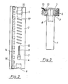
- An upper press plate 3 is held on a holder 1 via an angled holder area 2.
- This assembly holder 1, holding area 2 and upper press plate 3 can be made in one piece from an injection molded part.
- This upper press plate 3 is provided on one side with a support guide 4 and on the other side with a slide guide 5. Via the support guide 4 and the slide guide 5, the upper press plate 3 is interposed with a cleaning body 6 with a lower one Press plate 7 connected. On the lower press plate 7, a manual control 8 is provided on the side of the support guide 4, which at the same time has a locking shoulder 9. A holding hook 10 is formed on the sliding guide 5.
- the support guide 4 is additionally supported by a stiffening guide 11 which engages in an incision 12 in the lower press plate 7.
- the lower press plate 7 is further equipped with an insertion channel 13, which is provided with cutouts 1 on the sponge side. A wiper lip 15 is inserted into this insertion channel 13.
- the holding area 2 is provided with an undercut 16 for hanging the device on a bucket.
- the lower press plate 7 is further provided with water drainage openings 17 for the rapid discharge of the squeezed water.
- This water drainage openings 17 are expediently placed at a slant.
- FIG 4 the squeezing process of the device is shown.
- the upper press plate 3 and the lower press plate 7 are deflected.
- the lower press plate slides along the oblique guide 20 on the slide guide 5 and along the support guide 4 against the upper press plate 3.
- the oblique guide 20 compensates for the different length ratios when bending.
- the transition arch 21 between the holder 1 and the holding area 2 serves as a stop.
Abstract
Description
Die Erfindung bezieht sich auf ein Gerät zum Reinigen von Fensterscheiben, Fußböden und dergelichen Flächen gemäß dem Oberbegriff des Anspruchs 1.The invention relates to a device for cleaning window panes, floors and the like surfaces according to the preamble of
Nach der DE-GM 6 601 583 ist ein derartiges Gerät bekannt, bei dem die beiden Pressplatten gelenkig über Scharniere verbunden sind und sich über eine handbetätigte Stange V-förmig zusammenpressen lassen. Der auf den Pressplatten befestigte, schwammartige Reinigungskörper wird dabei allerdings ungleichmäßig stark zusammengedrückt, so daß eine sehr große Restfeuchte im Reinigungskörper verbleibt. Ein derartiges Gerät ist nur zur Grobreinigung von Fußböden geeignet. Eine Anwendung zur Reinigung von Fensterscheiben oder sonstiger ebener Flächen wie zum Beispiel Platten, Beläge in Bädern ist nur schwerlich denkbar.According to DE-GM 6 601 583, such a device is known in which the two press plates are connected in an articulated manner via hinges and can be pressed together in a V-shape by means of a manually operated rod. The sponge-like cleaning body attached to the press plates is, however, pressed together unevenly, so that a very large residual moisture remains in the cleaning body. Such a device is only suitable for rough cleaning of floors. An application for cleaning window panes or other flat surfaces such as tiles, coverings in bathrooms is hardly conceivable.
Aufgabe der Erfindung ist es, ein Gerät zum Reinigen von Fensterscheiben und sonstigen ebenen Flächen zu schaffen, das unter Verwendung eines auswechselbaren, schwammartigen Reinigungskörpers ein leichtes Auswringen des Reinigungskörpers ermöglicht und bei leichter, einfacher Handhabung eine nur geringe Restfeuchte gewährleistet. Es soll weiter verhindert werden, daß die Hände mit dem Schmutzwasser in Verbindung kommen.The object of the invention is to provide a device for cleaning window panes and other flat surfaces which, using an interchangeable, sponge-like cleaning body, enables the cleaning body to be easily wrung out and ensures only a low residual moisture with easy, simple handling. It should also be prevented that the hands come into contact with the dirty water.
Diese Aufgabe wird mit den kennzeichnenden Merkmalen des Anspruchs 1 gelöst.This object is achieved with the characterizing features of
Beim Verbiegen zweier in etwa parallel liegender Pressplatten mit dazwischen liegendem Reinigungskörper werden günstige Hebelverhältnisse erreicht, so daß eine hohe Presskraft auf den Reinigungskörper ausgeübt wird. Dennoch sind die Handkräfte gering und können in ergonomisch optimaler Haltung ausgeübt werden.When two approximately parallel pressing plates with a cleaning body lying between them are bent, favorable leverage ratios are achieved, so that a high pressing force is exerted on the cleaning body. Nevertheless, the hand forces are low and can be exercised in an ergonomically optimal posture.
Weitere Ausgestaltungen der Erfindung sind den Unteransprüchen zu entnehmen. Durch die parallele Anordnung des Schwammes mit einer Wischlippe ist es möglich, bei weniger beziehungsweise nur leicht verschmutzen Flächen diese in nur einem einzigen Arbeitsgang zu reinigen. Ein Abtropfen von Reinigungsflüssigkeit zum Beispiel beim Fensterreinigen wird zuverlässig verhindert.Further refinements of the invention can be found in the subclaims. Due to the parallel arrangement of the sponge with a wiper lip, it is possible to clean it with less or only slightly soiled surfaces in a single operation. Dripping of cleaning fluid, for example when cleaning windows, is reliably prevented.
Die Ausführung des Schwammes in unterschiedlichen Härtegrade ermöglicht es, zusätzlich auch hartnäckigen Schmutz sowie festsitzende Fliegen, zum Beispiel bei einer Autoscheibe, zu entfernen.The design of the sponge in different degrees of hardness makes it possible to also remove stubborn dirt and stuck flies, for example from a car window.
Die Anordung der Wischlippe in einem separaten Einschubkanal ermöglicht es, dieses Verschleißteil schnell zu wechseln. Die besonders Ausgestaltung des Einschubkanales mit Aussparungen beläßt der unteren Preßplatte ihre volle Elastizität.The arrangement of the wiper lip in a separate insertion channel enables this wear part to be changed quickly. The special design of the insertion channel with recesses leaves the lower press plate fully elastic.
Die besondere Ausführung der Gleitführung zwischen den beiden Pressplatten gewährleistet eine gleichmäßige Durchbiegung und somit ein gleichmäßiges Auspressen des Schwammes. Dies wird durch die spezielle Form des Halters, der im ersten Drittel der Länge gegenüber der Gleitführung die obere Pressplatte versteift, noch verbessert. Eine Hinterschneidung am Halterbereich ermöglicht das sichere Einhängen des Gerätes in, beziehungsweise an einem Reinigungseimer.The special design of the sliding guide between the two press plates ensures an even deflection and thus an even squeezing of the sponge. This is due to the special shape of the holder, which is the top in the first third of the length compared to the sliding guide Press plate stiffened, still improved. An undercut on the holder area enables the device to be securely hung in or on a cleaning bucket.
Zur guten Drainage ist die untere Pressplatte zusätzlich mit Abwasserablauföffnungen versehen.To ensure good drainage, the lower press plate has additional drainage openings.
Ein Ausführungsbeispiel der Erfindung wird im folgenden an Hand der Zeichnungen näher erläutert.An embodiment of the invention is explained below with reference to the drawings.
Es zeigen:
Figur 1 eine Ansicht eines Gerätes teilweise im Schnitt,- Figur 2 eine Ansicht gemäß der Richtung II in
Figur 1, Figur 3 eine Ansicht gemäß der Richtung III inFigur 1, undFigur 4 eine Seitenansicht des Gerätes beim Auspressvorgang.
- FIG. 1 shows a view of a device, partly in section,
- FIG. 2 shows a view in the direction II in FIG. 1,
- Figure 3 is a view in the direction III in Figure 1, and
- Figure 4 is a side view of the device during the squeezing process.
An einem Halter 1 ist über einen abgewinkelten Halterbereich 2 eine obere Pressplatte 3 gehalten. Diese Baugruppe Halter 1, Haltebereich 2 und obere Pressplatte 3 kann aus einem Spritzgußteil einstückig gefertigt sein.An
Diese obere Pressplatte 3 ist auf der einen Seite mit einer Stützführung 4 und auf der anderen Seite mit einer Gleitführung 5 versehen. Über die Stützführung 4 und die Gleitführung 5 ist die obere Pressplatte 3 unter Zwischenschaltung eines Reinigungskörpers 6 mit einer unteren Pressplatte 7 verbunden. An der unteren Pressplatte 7 ist an der Seite der Stützführung 4 eine Handbetätigung 8 vorgesehen, die gleichzeitig einen Rastabsatz 9 hat. An der Gleitführung 5 ist ein Haltehaken 10 angeformt. Die Stützführung 4 ist zusätzlich über eine Versteifungsführung 11, die in einem Einschnitt 12 in der unteren Pressplatte 7 eingreift, abgestützt.This
Die untere Pressplatte 7 ist weiter mit einem Einschubkanal 13, der auf der Schwammseite mit Aussparungen 1 versehen ist, ausgerüstet. In diesen Einschubkanal 13 ist eine Wischlippe 15 eingeschoben.The
Der Haltebereich 2 ist mit einer Hinterschneidung 16 zum Aufhängen des Gerätes an einem Eimer versehen.The holding area 2 is provided with an
Die untere Pressplatte 7 ist weiter mit Wasserablauföffnungen 17 zum schnellen Abführen des ausgepressten Wassers versehen. Dieses Wasserablauföffnungen 17 sind zweckmäßigerweise etwas schräg gestellt.The
In Figur 4 ist der Auspressvorgang des Gerätes dargestellt. Durch Halten des Gerätes mit der einen Hand am Halter 1 und Ziehen in Richtung 18 an der Handbetätigung 8 mit dem Finger 19 werden die obere Pressplatte 3 und die untere Pressplatte 7 durchgeboben. Dabei gleitet die untere Pressplatte entlang der Schrägführung 20 an der Gleitführung 5 und entlang der Stützführung 4 gegen die obere Pressplatte 3. Die Schrägführung 20 gleicht die unterschiedlichen Längenverhältnisse beim Durchbiegen aus. Der Übergangsbogen 21 zwischen Halter 1 und Haltebereich 2 dient dabei als Anschlag.In Figure 4, the squeezing process of the device is shown. By holding the device with one hand on the
Claims (12)
Priority Applications (1)
| Application Number | Priority Date | Filing Date | Title |
|---|---|---|---|
| EP19870103738 EP0286692B1 (en) | 1987-03-14 | 1987-03-14 | Apparatus for cleaning plane surfaces |
Applications Claiming Priority (1)
| Application Number | Priority Date | Filing Date | Title |
|---|---|---|---|
| EP19870103738 EP0286692B1 (en) | 1987-03-14 | 1987-03-14 | Apparatus for cleaning plane surfaces |
Publications (2)
| Publication Number | Publication Date |
|---|---|
| EP0286692A1 true EP0286692A1 (en) | 1988-10-19 |
| EP0286692B1 EP0286692B1 (en) | 1990-02-28 |
Family
ID=8196834
Family Applications (1)
| Application Number | Title | Priority Date | Filing Date |
|---|---|---|---|
| EP19870103738 Expired - Lifetime EP0286692B1 (en) | 1987-03-14 | 1987-03-14 | Apparatus for cleaning plane surfaces |
Country Status (1)
| Country | Link |
|---|---|
| EP (1) | EP0286692B1 (en) |
Cited By (2)
| Publication number | Priority date | Publication date | Assignee | Title |
|---|---|---|---|---|
| EP0356553A1 (en) * | 1988-08-31 | 1990-03-07 | Richard Banzer | Pressing device |
| WO2003061448A1 (en) * | 2002-01-22 | 2003-07-31 | Daniel Bastien | Squeegee implement |
Citations (3)
| Publication number | Priority date | Publication date | Assignee | Title |
|---|---|---|---|---|
| CH222516A (en) * | 1940-03-27 | 1942-07-31 | Weger Karl | Device for cleaning floors, walls, ceilings, windows, furniture and the like. |
| FR2106101A5 (en) * | 1970-08-28 | 1972-04-28 | Ognibene Pietro | |
| DE2715276A1 (en) * | 1977-04-05 | 1978-10-19 | Bosch Siemens Hausgeraete | Electric window cleaning device with heated contact surface - has moistened and heated outer cloth cover which provides steam cleaning |
-
1987
- 1987-03-14 EP EP19870103738 patent/EP0286692B1/en not_active Expired - Lifetime
Patent Citations (3)
| Publication number | Priority date | Publication date | Assignee | Title |
|---|---|---|---|---|
| CH222516A (en) * | 1940-03-27 | 1942-07-31 | Weger Karl | Device for cleaning floors, walls, ceilings, windows, furniture and the like. |
| FR2106101A5 (en) * | 1970-08-28 | 1972-04-28 | Ognibene Pietro | |
| DE2715276A1 (en) * | 1977-04-05 | 1978-10-19 | Bosch Siemens Hausgeraete | Electric window cleaning device with heated contact surface - has moistened and heated outer cloth cover which provides steam cleaning |
Cited By (2)
| Publication number | Priority date | Publication date | Assignee | Title |
|---|---|---|---|---|
| EP0356553A1 (en) * | 1988-08-31 | 1990-03-07 | Richard Banzer | Pressing device |
| WO2003061448A1 (en) * | 2002-01-22 | 2003-07-31 | Daniel Bastien | Squeegee implement |
Also Published As
| Publication number | Publication date |
|---|---|
| EP0286692B1 (en) | 1990-02-28 |
Similar Documents
| Publication | Publication Date | Title |
|---|---|---|
| EP1527728B1 (en) | Surface cleaning implement | |
| EP1308119B1 (en) | Plate frame for a cleaning device | |
| DE60212739T2 (en) | Improvements in or relating to Mopwringer | |
| DE102016118256B3 (en) | Cleaning system for floor cleaning | |
| DE3714178C2 (en) | Mop holder | |
| DE3136401C2 (en) | Multipurpose cleaning device | |
| EP0286692B1 (en) | Apparatus for cleaning plane surfaces | |
| DE19610160C2 (en) | Device for squeezing wet mop covers | |
| DE19601665C2 (en) | Press device for wet wipes | |
| EP1342445B1 (en) | Wiping mop | |
| EP0862888B1 (en) | Cleaning device | |
| DE202006002922U1 (en) | Mounting system for mop head with wringing system comprises longitudinal rib along top of sponge wiper and metal strip with U-shaped cross-section which fits over rib and has serrated edges which grip sponge | |
| WO2006067014A1 (en) | Mop with a flat holder | |
| DE4434065C1 (en) | Cleaning facility | |
| EP1972246A1 (en) | Device and method for cleaning mostly level surfaces | |
| DE3212274A1 (en) | RASP OF RASP | |
| EP1356757B1 (en) | Wet cleaning apparatus | |
| CH716668A2 (en) | Squeegee. | |
| EP0128225B1 (en) | Wiping mop | |
| WO2005080006A2 (en) | Device for forming joints | |
| DE8434817U1 (en) | Dust wiping holder | |
| DE4025280A1 (en) | Vehicle windscreen wiper assembly - incorporates easily assembled snap linkage to hold bows on rubber strip | |
| EP0310008A1 (en) | Spatula for kitchen use | |
| DE202006015209U1 (en) | Device for pressing a wet wiper coating placed on a wiper holder comprises a pressing plate with a lateral pressing edge protruding over the holder on the inlet side | |
| DE10301590B3 (en) | sealing knife |
Legal Events
| Date | Code | Title | Description |
|---|---|---|---|
| PUAI | Public reference made under article 153(3) epc to a published international application that has entered the european phase |
Free format text: ORIGINAL CODE: 0009012 |
|
| 17P | Request for examination filed |
Effective date: 19880309 |
|
| AK | Designated contracting states |
Kind code of ref document: A1 Designated state(s): AT BE CH DE FR GB IT LI LU NL SE |
|
| RBV | Designated contracting states (corrected) |
Designated state(s): FR GB IT NL |
|
| REG | Reference to a national code |
Ref country code: DE Ref legal event code: 8566 |
|
| 17Q | First examination report despatched |
Effective date: 19890308 |
|
| GRAA | (expected) grant |
Free format text: ORIGINAL CODE: 0009210 |
|
| AK | Designated contracting states |
Kind code of ref document: B1 Designated state(s): FR GB IT NL |
|
| ITF | It: translation for a ep patent filed |
Owner name: DE DOMINICIS & MAYER S.R.L. |
|
| GBT | Gb: translation of ep patent filed (gb section 77(6)(a)/1977) | ||
| ET | Fr: translation filed | ||
| PLBE | No opposition filed within time limit |
Free format text: ORIGINAL CODE: 0009261 |
|
| STAA | Information on the status of an ep patent application or granted ep patent |
Free format text: STATUS: NO OPPOSITION FILED WITHIN TIME LIMIT |
|
| 26N | No opposition filed | ||
| ITTA | It: last paid annual fee | ||
| PGFP | Annual fee paid to national office [announced via postgrant information from national office to epo] |
Ref country code: NL Payment date: 19950331 Year of fee payment: 9 |
|
| PG25 | Lapsed in a contracting state [announced via postgrant information from national office to epo] |
Ref country code: NL Effective date: 19961001 |
|
| NLV4 | Nl: lapsed or anulled due to non-payment of the annual fee |
Effective date: 19961001 |
|
| PGFP | Annual fee paid to national office [announced via postgrant information from national office to epo] |
Ref country code: GB Payment date: 19990205 Year of fee payment: 13 |
|
| PGFP | Annual fee paid to national office [announced via postgrant information from national office to epo] |
Ref country code: FR Payment date: 19990210 Year of fee payment: 13 |
|
| PG25 | Lapsed in a contracting state [announced via postgrant information from national office to epo] |
Ref country code: GB Free format text: LAPSE BECAUSE OF NON-PAYMENT OF DUE FEES Effective date: 20000314 |
|
| GBPC | Gb: european patent ceased through non-payment of renewal fee |
Effective date: 20000314 |
|
| PG25 | Lapsed in a contracting state [announced via postgrant information from national office to epo] |
Ref country code: FR Free format text: LAPSE BECAUSE OF NON-PAYMENT OF DUE FEES Effective date: 20001130 |
|
| REG | Reference to a national code |
Ref country code: FR Ref legal event code: ST |
|
| PG25 | Lapsed in a contracting state [announced via postgrant information from national office to epo] |
Ref country code: IT Free format text: LAPSE BECAUSE OF NON-PAYMENT OF DUE FEES;WARNING: LAPSES OF ITALIAN PATENTS WITH EFFECTIVE DATE BEFORE 2007 MAY HAVE OCCURRED AT ANY TIME BEFORE 2007. THE CORRECT EFFECTIVE DATE MAY BE DIFFERENT FROM THE ONE RECORDED. Effective date: 20050314 |
|
| PGFP | Annual fee paid to national office [announced via postgrant information from national office to epo] |
Ref country code: IT Payment date: 20060331 Year of fee payment: 20 |
|
| PGRI | Patent reinstated in contracting state [announced from national office to epo] |
Ref country code: IT Effective date: 20080301 |