EP0285424B1 - Dispositif pour réunir des matériaux comme des médicaments avec un liquide - Google Patents
Dispositif pour réunir des matériaux comme des médicaments avec un liquide Download PDFInfo
- Publication number
- EP0285424B1 EP0285424B1 EP19880302899 EP88302899A EP0285424B1 EP 0285424 B1 EP0285424 B1 EP 0285424B1 EP 19880302899 EP19880302899 EP 19880302899 EP 88302899 A EP88302899 A EP 88302899A EP 0285424 B1 EP0285424 B1 EP 0285424B1
- Authority
- EP
- European Patent Office
- Prior art keywords
- cup
- vial
- conduit
- container
- interior
- Prior art date
- Legal status (The legal status is an assumption and is not a legal conclusion. Google has not performed a legal analysis and makes no representation as to the accuracy of the status listed.)
- Expired - Lifetime
Links
Images


Classifications
-
- A—HUMAN NECESSITIES
- A61—MEDICAL OR VETERINARY SCIENCE; HYGIENE
- A61J—CONTAINERS SPECIALLY ADAPTED FOR MEDICAL OR PHARMACEUTICAL PURPOSES; DEVICES OR METHODS SPECIALLY ADAPTED FOR BRINGING PHARMACEUTICAL PRODUCTS INTO PARTICULAR PHYSICAL OR ADMINISTERING FORMS; DEVICES FOR ADMINISTERING FOOD OR MEDICINES ORALLY; BABY COMFORTERS; DEVICES FOR RECEIVING SPITTLE
- A61J1/00—Containers specially adapted for medical or pharmaceutical purposes
- A61J1/14—Details; Accessories therefor
- A61J1/20—Arrangements for transferring or mixing fluids, e.g. from vial to syringe
- A61J1/2089—Containers or vials which are to be joined to each other in order to mix their contents
-
- A—HUMAN NECESSITIES
- A61—MEDICAL OR VETERINARY SCIENCE; HYGIENE
- A61J—CONTAINERS SPECIALLY ADAPTED FOR MEDICAL OR PHARMACEUTICAL PURPOSES; DEVICES OR METHODS SPECIALLY ADAPTED FOR BRINGING PHARMACEUTICAL PRODUCTS INTO PARTICULAR PHYSICAL OR ADMINISTERING FORMS; DEVICES FOR ADMINISTERING FOOD OR MEDICINES ORALLY; BABY COMFORTERS; DEVICES FOR RECEIVING SPITTLE
- A61J1/00—Containers specially adapted for medical or pharmaceutical purposes
- A61J1/05—Containers specially adapted for medical or pharmaceutical purposes for collecting, storing or administering blood, plasma or medical fluids ; Infusion or perfusion containers
- A61J1/10—Bag-type containers
-
- A—HUMAN NECESSITIES
- A61—MEDICAL OR VETERINARY SCIENCE; HYGIENE
- A61J—CONTAINERS SPECIALLY ADAPTED FOR MEDICAL OR PHARMACEUTICAL PURPOSES; DEVICES OR METHODS SPECIALLY ADAPTED FOR BRINGING PHARMACEUTICAL PRODUCTS INTO PARTICULAR PHYSICAL OR ADMINISTERING FORMS; DEVICES FOR ADMINISTERING FOOD OR MEDICINES ORALLY; BABY COMFORTERS; DEVICES FOR RECEIVING SPITTLE
- A61J1/00—Containers specially adapted for medical or pharmaceutical purposes
- A61J1/14—Details; Accessories therefor
- A61J1/1462—Containers with provisions for hanging, e.g. integral adaptations of the container
-
- A—HUMAN NECESSITIES
- A61—MEDICAL OR VETERINARY SCIENCE; HYGIENE
- A61J—CONTAINERS SPECIALLY ADAPTED FOR MEDICAL OR PHARMACEUTICAL PURPOSES; DEVICES OR METHODS SPECIALLY ADAPTED FOR BRINGING PHARMACEUTICAL PRODUCTS INTO PARTICULAR PHYSICAL OR ADMINISTERING FORMS; DEVICES FOR ADMINISTERING FOOD OR MEDICINES ORALLY; BABY COMFORTERS; DEVICES FOR RECEIVING SPITTLE
- A61J1/00—Containers specially adapted for medical or pharmaceutical purposes
- A61J1/14—Details; Accessories therefor
- A61J1/1475—Inlet or outlet ports
-
- A—HUMAN NECESSITIES
- A61—MEDICAL OR VETERINARY SCIENCE; HYGIENE
- A61J—CONTAINERS SPECIALLY ADAPTED FOR MEDICAL OR PHARMACEUTICAL PURPOSES; DEVICES OR METHODS SPECIALLY ADAPTED FOR BRINGING PHARMACEUTICAL PRODUCTS INTO PARTICULAR PHYSICAL OR ADMINISTERING FORMS; DEVICES FOR ADMINISTERING FOOD OR MEDICINES ORALLY; BABY COMFORTERS; DEVICES FOR RECEIVING SPITTLE
- A61J1/00—Containers specially adapted for medical or pharmaceutical purposes
- A61J1/14—Details; Accessories therefor
- A61J1/20—Arrangements for transferring or mixing fluids, e.g. from vial to syringe
- A61J1/2003—Accessories used in combination with means for transfer or mixing of fluids, e.g. for activating fluid flow, separating fluids, filtering fluid or venting
- A61J1/2006—Piercing means
- A61J1/201—Piercing means having one piercing end
-
- A—HUMAN NECESSITIES
- A61—MEDICAL OR VETERINARY SCIENCE; HYGIENE
- A61J—CONTAINERS SPECIALLY ADAPTED FOR MEDICAL OR PHARMACEUTICAL PURPOSES; DEVICES OR METHODS SPECIALLY ADAPTED FOR BRINGING PHARMACEUTICAL PRODUCTS INTO PARTICULAR PHYSICAL OR ADMINISTERING FORMS; DEVICES FOR ADMINISTERING FOOD OR MEDICINES ORALLY; BABY COMFORTERS; DEVICES FOR RECEIVING SPITTLE
- A61J1/00—Containers specially adapted for medical or pharmaceutical purposes
- A61J1/14—Details; Accessories therefor
- A61J1/20—Arrangements for transferring or mixing fluids, e.g. from vial to syringe
- A61J1/2003—Accessories used in combination with means for transfer or mixing of fluids, e.g. for activating fluid flow, separating fluids, filtering fluid or venting
- A61J1/2006—Piercing means
- A61J1/2013—Piercing means having two piercing ends
Definitions
- the present invention relates to apparatus for contacting material such as a drug with a fluid. It particularly relates to apparatus by means of which material can be contacted with a fluid in a closed system.
- WO-A-8 503 432 discloses a closed drug delivery system comprising a flexible container of fluid, a cup permanently coupled to the container, and a standard glass drug vial within the cup, which is permanently closed by a cap.
- the cap is deformable to urge the vial downwardly, whereby a spike at the end of a conduit leading into the container is urged into the vial.
- liquid from the container can contact material in the vial.
- This system has some disadvantages. It is a sealed unit, including the container of fluid and the vial of drug. Thus every possible combination of fluid and drug must be manufactured and stocked. A manufacturer who produces containers of fluid may not wish to involve himself with the cup portions and vials of drugs and in any case it would be desirable for the same containers to be usable in other manners.
- a given cup is only suitable for a single size and shape of vial.
- the invention enables one to ameliorate one or more of the above drawbacks.
- the invention provides apparatus for use in establishing flow communication between the interior of a vial and the interior of a container, said apparatus comprising cup means for receiving a dispensing end portion of the vial, and a retainer means for retaining the vial with its end portion inserted in the cup means; said cup means having a mouth portion through which said end portion of the vial is insertable, a base portion opposed to said mouth portion, and conduit means communicating the interior of the cup means with the exterior, said conduit means being communicable with a container to establish said flow communication, and comprising a tubular spike projecting into the cup means from said base portion so as to confront said end portion of the vial, so that the vial is urgeable axially within the cup means against the spike whereby the interior of the vial is communicable with the interior of a container via said conduit means characterised in that said cup means and retainer means have complementary engagement formations such that the retainer means is engageable with the cup
- the retainer means is adapted to be urgeable against a vial inserted in the cup means to urge the vial against the spike, and the engagement formations are such that the retainer means is displaceable axially relative to the cup means during engagement; the locking means being arranged so that the operation of engaging them, so that the vial is retained non-removably, brings the vial interior into flow communication with the conduit means.
- the complementary engagement can take various forms.
- a simple arrangement is for the retainer means (or lid) and the cup means to have respective ones of a ratchet and detent means, arranged to be mutually engageable but not disengageable.
- the engagement means may employ a thread within the cup.
- the lid may then have an external thread or thread portions (e.g. lugs, e.g. as in a Luer lock).
- the locking means may comprise engagement means provided by the cup means for irreversibly engaging a vial.
- Cup means may be permanently connected to a container.
- a container may have connecting means for coupling with complementary means associated with the cup. These may comprise a thread and a Luer lock.
- complementary means associated with the cup may comprise a thread and a Luer lock.
- there are means for rendering their engagement irreversible e.g. a ratchet arrangement similar to that described above. Storage of fluid containers can be more efficient when they are not coupled to the cups.
- a further way of permitting this is for the cup to have an external tubular spike portion so that it can be brought into communication with a container by pushing a spike through a rubber septum or the like provided by the container.
- a rubber septum or the like provided by the container.
- Spacers may be provided so that different types of vial can be used with the same cup.
- the cup may have a cup-shaped lid into which vials can be fitted, with the interposition of spacer means as required.
- the invention provides a drug delivery system comprising apparatus according to the first aspect, and a container for liquid; the conduit means being in communication or communicable with the interior of the container.
- a sterile fluid container 10 has a conduit 12 extending from the interior to the exterior. At the interior, it is closed by a breakable seal 14. At the outer end, it has the external formations 16 of a Luer lock. A little way beneath these, there are some detents 18, which are small flexible vanes.
- the conduit 12 may be provided with a filter to trap any debris produced by breaking the seal. As shown in Figs. 1 and 2, this may comprise a filter sheath 80 about the end portion of the conduit 12. This may be provided by a flat tube of filter material, e.g. nylon mesh, sealed at its lower end region 82. The upper end region of the sheath may be sealed into the container 10 by the sealing step that forms the upper seal 74 of the container.
- a filter to trap any debris produced by breaking the seal.
- this may comprise a filter sheath 80 about the end portion of the conduit 12. This may be provided by a flat tube of filter material, e.g. nylon mesh, sealed at its lower end region 82. The upper end region of the sheath may be sealed into the container 10 by the sealing step that forms the upper seal 74 of the container.
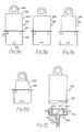
- FIG. 3 shows an alternative form of conduit 12 ⁇ .
- This has an internal breakable barrier 14 ⁇ of known type (employing axial vanes 17). Downstream of this, a widened portion 79 of the conduit houses a porous disc filter 80 ⁇ . Alternatively the filter 80 ⁇ can be housed in a separate tube portion which is attached to the end of the conduit.
- a cup assembly 20 includes a plastics cup member 22. In the base thereof there is a central opening 24, which extends outwardly through a spigot portion 26. A short conduit 28 is sealed to this, and terminates in a socket portion 30 having an internal thread 32 for engaging the Luer lock formations 16.
- the socket portion 30 has an enlarged mouth portion 34 within which there are ratchet teeth. The arrangement is such that the socket portion 30 and conduit 12 can be screwed together. Finally the detents 18 engage the ratchet teeth 36, which prevent unscrewing.
- Fig. 2 shows a variant in which the cup assembly 20 is permanently connected to the fluid container 10.
- the spigot portion 26 has been extended and made integral with the conduit 12 that is sealed into the container 10.
- the cup member 22 has an internal thread 38.
- a short cylindrical wall 40 extends axially from the base, a short distance radially within the thread 38.
- the upper mouth region of the cup 22 has an enlarged mouth portion 42, which is formed with ratchet teeth 44. Finally, there is a peripheral flange 46.
- a vial 48 is housed within a housing 50. As shown, the vial 48 fits snugly within the housing 50, abutting the end thereof such that the mouth of the vial 48 projects slightly beyond the housing 50. To enable the same housing 50 to be used with differently dimensioned vials, spacers may be employed. Fig. 4 shows a spacer 52 which is an annulus 54 with five equispaced ribs 56 dimensioned to contact the inner wall of the housing 50. For use with a short vial 48, the spacer may itself be cup-shaped to take up the excessive length.
- FIGs. 5 and 6 show a spacer assembly having a wide tolerance.
- An injection-moulded plastics blank 90 has three rectangular panels 91 hinged together in a row by thinned regions 92. Each panel has a transverse slot 93.
- a disc 94 with an annular rib 95 is connected to one panel 91 by a nib 96. For use, the disc 94 is snapped off and the array of panels is folded to define approximately a trigonal prism, within which a vial may be housed.
- the disc 94 may be omitted or mounted in the slots 93 to provide an end wall.
- the effective depth of the vial housing is variable by orienting the disc with the rib projecting upwardly or downwardly.
- a plurality of sets of slots 93 may be provided.
- the vial 48 is of conventional type, having a neck 49 leading to a mouth with an annular rim.
- the mouth is closed by a cap 58 with an aluminium collar 59 engaged over the rim, and a penetrable rubber septum 60.
- the housing 50 has lugs 62 adjacent its open lower end. These are threadedly engageable with the thread 38 within the cup member 22. At an intermediate region, the housing 50 has tangentially projecting external vanes 64. Just above them, there may be an annular flange 65. Thus, when the housing 50 is screwed into the cup member 22, this is initially reversible. However, towards the end of its travel, the vanes 64 engage the ratchet 44, and the engagement becomes irreversible. The engagement becomes still more firm and positive because a mouth region 66 of the housing becomes engaged between the outer wall of the cup 22 and the cylindrical wall 40. If the flange 65 is present, it covers the ratchet means 44,64 thus making it still more difficult for someone to force disengagement.
- the cup member contains a tubular spike 70 which passes sealingly through the aperture 24. This is dimensioned so that, when a housing 50 containing a vial 48 is screwed into the cup member 22, the spike 70 is driven through the rubber septum 60 into the interior of the vial 48. This does not occur until the vanes 64 engage the ratchet 44.
- a sheath portion 74 may initially cover the spike 70, and be ruptured by the vial.
- an appropriate vial and an appropriate receptacle 10 of fluid are selected.
- the rubber septum 60 of the vial is swabbed with a sterilising fluid.
- the cup assembly 20 is secured irreversibly to the container 10.
- the vial is engaged in the housing 50, using a spacer if necessary.
- the housing 50 is then screwed down into the cup member 22, so that the spike 70 is urged into the vial.
- the sealed end 14 of the conduit 12 can be snapped off.
- the interior of the receptacle 10 and the interior of the vial 48 are in flow communication. This has been achieved under normal aseptic handling conditions, and the arrangement is tamper-proof. Fluid can be pumped from the receptacle 10 into the vial 48 and back again by squeezing the receptacle 10, in generally known fashion.
- Particulate contamination produced by breaking the seal (14 or 14 ⁇ ) or particulate material from the cup member 22, e.g. undissolved drug particles, will be filtered out by the filter (80 or 80 ⁇ ).
- FIGs. 9 A-D show housings 190 formed in two parts: a standard lower portion 192, providing the ratchet vanes 64 and the screw lugs 62; and an upper portion 194 which provides the base 196 and a suspension loop 198.
- a flange 65 can be provided at the zone of connection.
- the different upper portions 194 are adapted to different lengths and diameters of vials.
- the cup assembly may be sealed for storage under sterile conditions. Thus there may be a peelable diaphragm across the cup mouth, and a similar or different seal across the lower mouth 34.
- a conventional peelable diaphragm across the cup mouth may give rise to problems, e.g. if paper tear brings a risk of particulate contamination of the cup interior.
- a diaphragm assembly 160 which provides a clean tear.
- a suitable assembly is shown in Fig. 7. It may be injection moulded from pvc optionally blended with a nitrile rubber.
- An annular outer portion 161 may be welded to the flange 46 to close the open mouth of the cup member 22.
- the illustrated assembly 160 has a circular disc having a central depressed portion 162 and an outer flange 164. In an intermediate region the flange 164 has an annular "thinned" region 166 which forms a tear line.
- a finger pull tab 168 may be formed on the flange inwardly of the thinned region 166. In use, this is pulled to tear away the assemble within the thinned region 166, leaving a cleanly exposed cup member 22. It has been found that, during autoclaving, the external pressure may force the central portion 162 down into the cup so far that it may be damaged by the spike 70. It may be shaped to minimise this risk, e.g. being connected to the flange 164 via an annulus that extends upwardly from the flange 164. Alternatively or additionally, the diaphragm may have a porous region for preventing the formation of large pressure differences across it. This may be provided as shown in Fig. 12. An aperture 400 is provided in the central portion 162.
- a filter membrane 402 is laid over it, and a plastics annular washer 404 is placed on the membrane.
- the washer may have a flat flange portion 408 with a raised rib 406 surrounding the aperture.
- the flange portion 408 of the washer is sealed to the central portion 162 of the diaphragm through the membrane 402 by a suitable technique, e.g. RF, heat or ultrasonic welding, depending on the materials involved.
- the filter membrane 402 is selected to provide sufficient porosity while still serving as a barrier to microorganisms.
- it may be a filter medium of nylon-6,6 (e.g. as available under the trademarks Ultipor and Posidyne from Pall Process Filtration Ltd.), e.g. with a pore size of 2 ⁇ m.
- Fig. 8 shows a modified cup assembly 20 ⁇ , differing from that shown in Fig. 1 in that the spigot portion 26 ⁇ terminates in a conduit portion 98 carrying a tubular spike 99.
- the cup assembly 20′ when containing a vial
- a fluid container shown schematically at 10 ⁇
- an administration port 12 ⁇ generally having a penetrable septum 14 ⁇
- Fig. 10 shows another embodiment.
- the cup assembly 120 includes a plastics cup member 122 of smaller axial extent. Its central opening 124, spigot portions 126 etc. may be as previously described, and are open to similar modifications.
- the housing can be pushed into the cup member 122, and its rib 162 clips behind one or more ribs 138 of the cup member 122 and is, for practical purposes, unreleasable.
- This is achieved more simply than in the Fig. 1 embodiment which requires not only threaded engagement means 62,38 but also the relatively elaborate ratchet means 64,44.
- this form of detent means is not restricted to this embodiment. Ribs (162 and/or 138) could be replaced by projections.
- Fig. 11 shows fluid container 210 and cup assembly 220 of a further embodiment of the invention.
- the container 210 has a conduit 212 extending into its interior. Initially the exterior of the conduit 212 opens in an expansion chamber 300. This is provided by an end portion 302 of the container delimited by a tear line 304 so it can be torn away to expose the end of the conduit 212.
- An insert 306 of polycarbonate plastics material projects from the inner end of the conduit 212. It is initially just a push-fit within the conduit, its degree of insertion delimited by a flange 307, but becomes bonded during heat sterilisation.
- the insert 306 provides (from the outer end) an internally threaded portion 308, a location taper 310 (of standard Luer type), and a breakable barrier 217 which closes the conduit 212.
- a lower conduit portion 312 is pushed over the projecting lower part of the insert 306 to retain the broken off part of the barrier 217 when it is snapped.
- the lower conduit portion 312 may have apertures to facilitate flow once the barrier 217 is broken.
- the cup assembly 220 comprises a cup member 222 (possibly of K resin) which may be generally as any previously described. Its base has a central spigot 226. This has an external thread 314 complementary to the threaded portion 308 of the insert in the container 210. (They may be two-stage threads to give rapid engagement.) An end portion 316 of the spigot 226 has an external taper complementary to the location taper 310. The spigot 226 may initially be protected by a disposable cover 318.
- the conduit 212 and spigot 226 are exposed by removal of the expansion chamber 300 and cover 318.
- the spigot 226 is screwed into the insert within the conduit until the tapered portions 310,316 engage. Locking means prevent disengagement.
- Apparatus embodying the invention is also useful in the field of blood products.
- an unfilled fluid container 10 coupled with a cup assembly (e.g. 20), with a housing (e.g. 50) inserted partially (and therefore removably) into the cup member; the whole assembly being sealed in a pouch and sterilised, suitably by gamma irradiation or steam sterilisation.
- Use of steam sterilisation under pressure may tend to cause the housing 50 to become deformed. This can be avoided by providing the housing 50 or cup member 22 with controlled gas permeability.
- the housing 50 is provided with a porous region as described above with reference to Fig. 12 for the cup diaphragm 160.
- Such a filter membrane 402 allows steam to gain access to the interior of the housing, even if its open end is closed by insertion into the cup member 22. For use it is removed from the pouch and the container is filled with (e.g.) blood plasma. The housing is removed to enable a vial of medicament to be selected, inserted, and brought into contact with the plasma by means of the assembly.
- one or more apertures 500 are provided in the base of the cup member 22, in the region between the side wall of the cup and the inner cylindrical wall 40.
- gases e.g. air and steam
- the apertures 500 are closed by the leading edge of the housing 50.
Claims (15)
- Dispositif destiné à être utilisé pour établir une communication d'écoulement entre l'intérieur d'un flacon (48) et l'intérieur d'un conteneur (10), ledit dispositif comprenant des moyens formant gobelet (22, 122; 222), destiné à recevoir une partie d'extrémité de distribution (58) du flacon (48), et un moyen de retenue (50; 150; 190) pour retenir le flacon (48) dont la partie d'extrémité est insérée dans le moyen formant gobelet; lesdits moyens formant gobelet (22; 122; 222) possédant une partie d'embouchure (42) à travers laquelle ladite partie d'extrémité du flacon (48) peut être insérée, une partie d'embase opposée à ladite partie d'embouchure, et des moyens de conduit (26; 126; 226) faisant communiquer l'intérieur du moyen formant gobelet avec l'extérieur, ledit moyen de conduit (26; 126; 226) pouvant être mis en communication avec un conteneur (10) pour établir ladite communication d'écoulement, et comprenant une broche tubulaire (70; 170) en saillie dans le moyen formant gobelet (22; 122) depuis ladite partie d'embase de manière à confronter ladite partie extrême du flacon (48); de façon que le flacon (48) puisse être sollicité dans le sens axial à l'intérieur du moyen formant gobelet à l'encontre de la pointe par quoi l'intérieur du flacon (48) peut communiquer avec l'intérieur du conteneur (10) via ledit moyen de conduit (26;126 ; 226);
caractérisé en ce que ledit moyen de gobelet (22; 122; 222) et les moyens de retenue (50; 150; 190) possèdent des formations d'engagement complémentaires (62,38; 162, 138) de sorte que le moyen de retenue (50; 150, 190) puisse venir en prise avec le moyen formant gobelet (22; 122), lesdites formations d'engagement comprenant des moyens de verrouillage (44, 64, 141) pouvant venir en prise pour verrouiller le moyen de retenue aux moyens formant gobelet, lesdits moyens formant gobelet et lesdits moyens de retenue étant séparés ou séparables initialement pour permettre l'insertion d'un flacon, et ensuite verrouillables par engagement du moyen de verrouillage, de sorte que le flacon est immobilisé dans celui-ci. - Dispositif selon la revendication 1, dans lequel le moyen de retenue (50;150;190) est destiné à pouvoir être sollicité contre un flacon (48) inséré dans le moyen de gobelet (22;122) pour solliciter le gobelet (48) contre la broche (70;170), et les formations d'engagement (62,38;162,138) sont telles que les moyens de retenue (50;150;190) peuvent être déplacés dans le sens axial par rapport aux moyens formant gobelet (22;122) pendant l'engagement; les moyens de verrouillage (44,64,141) étant agencés de façon que l'opération de leur mise en prise, de façon que le flacon soit retenu de manière non-mobile, amène l'intérieur du flacon en communication d'écoulement avec le moyen de conduit.
- Dispositif selon la revendication 1 ou 2, dans lequel lesdites formations d'engagement complémentaires comprennent des moyens d'engagement filetés (62,38) et des moyens à cliquet (44,64) de sorte qu'une prise filetée est permise, mais qu'un dégagement fileté est empêché.
- Dispositif selon la revendication 1 ou 2, dans lequel lesdits moyens d'engagement complémentaires comprennent des nervures annulaires (138) de section transversale en dents de scie sur un élément et au moins une nervure ou saillie complémentaire (162) sur l'autre.
- Dispositif selon l'une des revendications précédentes, dans lequel ledit moyen de retenue (50;150;190) comprend un manchon cylindrique pour entourer le flacon et ledit moyen de gobelet comprend une paroi annulaire de gobelet et une paroi annulaire interne coaxiale (40;140); la disposition étant telle que le moyen de retenue (50;150;190) peut être déplacé vers une configuration dans laquelle son manchon est en saillie de manière bien adaptée entre la paroi annulaire de gobelet et la paroi annulaire interne coaxiale (40;140).
- Dispositif selon la revendication 5, dans lequel ladite paroi annulaire interne (140) possède un bourrelet de détente (141) en saillie vers l'intérieur dimensionné et positionné de sorte que le flacon (48) possédant un couvercle (58,59) est sollicité axialement à l'intérieur du moyen formant gobelet (122), le couvercle (58,59) est contraint devant le bourrelet de détente (141) et résiste ensuite à son enlèvement.
- Dispositif selon la revendication 5 ou 6, comprenant une pluralité de moyens de retenue (190) pouvant être mis en prise sélectivement avec le moyen de gobelet, et fournissant des manchons cylindriques aptes à entourer des flacons de dimensions différentes respectives.
- Dispositif selon l'une des revendications précédentes, comprenant en outre au moins une pièce d'écartement (52;90) dimensionnée pour s'adapter de manière bien ajustée à l'intérieur du moyen de gobelet (22;122;222) et destinée à maintenir le flacon (48) qui serait autrement maintenue lâchement à l'intérieur du moyen formant gobelet.
- Dispositif selon l'une des revendications précédentes, dans lequel ledit moyen de conduit (26;226) possède une partie d'extrémité extérieure (30;314) apte à être couplée audit second moyen de conduit (12;212) associé à un conteneur (10;210) avec l'intérieur duquel la communication doit être établie.
- Dispositif selon l'une des revendications précédentes, comprenant un diaphragme (160) par lequel la partie d'embouchure du moyen formant gobelet (22) est fermée, ledit diaphragme (160) possédant une partie adaptée (166) à être enlevée pour permettre la venue en prise dudit moyen de retenue et du flacon.
- Dispositif selon l'une des revendications précédentes, dans lequel ledit moyen de conduit (26') se termine à l'extérieur du moyen formant gobelet dans une pointe tubulaire (99).
- Système de distribution de médicaments comprenant un dispositif selon l'une des revendications précédentes et un conteneur pour un liquide (10;210); ledit moyen de conduit (26;126;226) étant en communication ou pouvant communiquer avec l'intérieur du conteneur.
- Système de distribution de médicaments selon la revendication 12, dans lequel le moyen de conduit comprend un premier moyen de conduit (26;226) communiquant avec l'intérieur du moyen formant gobelet et un second moyen de conduit (12;212) communiquant avec l'intérieur du conteneur; lesdits premier et second moyens de conduit possédant des formations complémentaires (16,32;314,308), par lesquelles ils peuvent être accouplés ensemble; lesdites formations complémentaires étant destinées (18,36; 320,322) pour permettre l'accouplement et pour empêcher le désaccouplement.
- Système de distribution de médicaments selon la revendication 12 ou 13, dans lequel le conteneur présente une partie de conduit pour ladite communication d'écoulement; ladite partie de conduit de conteneur possédant des moyens formant frange (14;14') qui empêchent ladite communication d'écoulement jusqu'à ce qu'ils soient cassés.
- Système de distribution de médicaments selon la revendication 14, comprenant un élément de retenue de matière particulaire (80;81') disposé pour immobiliser de la matière particulaire produite par la rupture desdits moyens formant frange.
Priority Applications (1)
| Application Number | Priority Date | Filing Date | Title |
|---|---|---|---|
| AT88302899T ATE79249T1 (de) | 1987-04-02 | 1988-03-31 | Vorrichtung zum zusammenbringen von stoffen, wie arzneimitteln, mit einer fluessigkeit. |
Applications Claiming Priority (4)
| Application Number | Priority Date | Filing Date | Title |
|---|---|---|---|
| GB8707917 | 1987-04-02 | ||
| GB878707917A GB8707917D0 (en) | 1987-04-02 | 1987-04-02 | Contacting material |
| GB888803324A GB8803324D0 (en) | 1987-04-02 | 1988-02-12 | Apparatus for contacting material such as drug with fluid |
| GB8803324 | 1988-02-12 |
Publications (2)
| Publication Number | Publication Date |
|---|---|
| EP0285424A1 EP0285424A1 (fr) | 1988-10-05 |
| EP0285424B1 true EP0285424B1 (fr) | 1992-08-12 |
Family
ID=26292090
Family Applications (1)
| Application Number | Title | Priority Date | Filing Date |
|---|---|---|---|
| EP19880302899 Expired - Lifetime EP0285424B1 (fr) | 1987-04-02 | 1988-03-31 | Dispositif pour réunir des matériaux comme des médicaments avec un liquide |
Country Status (12)
| Country | Link |
|---|---|
| US (1) | US5061264A (fr) |
| EP (1) | EP0285424B1 (fr) |
| JP (1) | JPH02503272A (fr) |
| AU (1) | AU623076B2 (fr) |
| CA (1) | CA1302837C (fr) |
| DE (1) | DE3873579T2 (fr) |
| DK (1) | DK160738C (fr) |
| ES (1) | ES2035277T3 (fr) |
| FI (1) | FI894655A0 (fr) |
| GB (1) | GB2230001B (fr) |
| IE (1) | IE62230B1 (fr) |
| WO (1) | WO1988007358A1 (fr) |
Cited By (21)
| Publication number | Priority date | Publication date | Assignee | Title |
|---|---|---|---|---|
| US6582415B1 (en) | 1998-09-15 | 2003-06-24 | Thomas A. Fowles | Sliding reconstitution device for a diluent container |
| US6610040B1 (en) | 1997-12-04 | 2003-08-26 | Baxter International Inc. | Sliding reconstitution device with seal |
| US7867215B2 (en) | 2002-04-17 | 2011-01-11 | Carmel Pharma Ab | Method and device for fluid transfer in an infusion system |
| USD637713S1 (en) | 2009-11-20 | 2011-05-10 | Carmel Pharma Ab | Medical device adaptor |
| US7942860B2 (en) | 2007-03-16 | 2011-05-17 | Carmel Pharma Ab | Piercing member protection device |
| US7975733B2 (en) | 2007-05-08 | 2011-07-12 | Carmel Pharma Ab | Fluid transfer device |
| US8029747B2 (en) | 2007-06-13 | 2011-10-04 | Carmel Pharma Ab | Pressure equalizing device, receptacle and method |
| US8075550B2 (en) | 2008-07-01 | 2011-12-13 | Carmel Pharma Ab | Piercing member protection device |
| US8162013B2 (en) | 2010-05-21 | 2012-04-24 | Tobias Rosenquist | Connectors for fluid containers |
| US8287513B2 (en) | 2007-09-11 | 2012-10-16 | Carmel Pharma Ab | Piercing member protection device |
| US8328772B2 (en) | 2003-01-21 | 2012-12-11 | Carmel Pharma Ab | Needle for penetrating a membrane |
| US8480646B2 (en) | 2009-11-20 | 2013-07-09 | Carmel Pharma Ab | Medical device connector |
| US8523838B2 (en) | 2008-12-15 | 2013-09-03 | Carmel Pharma Ab | Connector device |
| US8545475B2 (en) | 2002-07-09 | 2013-10-01 | Carmel Pharma Ab | Coupling component for transmitting medical substances |
| US8562583B2 (en) | 2002-03-26 | 2013-10-22 | Carmel Pharma Ab | Method and assembly for fluid transfer and drug containment in an infusion system |
| US8622985B2 (en) | 2007-06-13 | 2014-01-07 | Carmel Pharma Ab | Arrangement for use with a medical device |
| US8657803B2 (en) | 2007-06-13 | 2014-02-25 | Carmel Pharma Ab | Device for providing fluid to a receptacle |
| US8790330B2 (en) | 2008-12-15 | 2014-07-29 | Carmel Pharma Ab | Connection arrangement and method for connecting a medical device to the improved connection arrangement |
| US8827978B2 (en) | 2007-09-17 | 2014-09-09 | Carmel Pharma Ab | Bag connector |
| US9168203B2 (en) | 2010-05-21 | 2015-10-27 | Carmel Pharma Ab | Connectors for fluid containers |
| US11071818B2 (en) | 2007-08-30 | 2021-07-27 | Carmel Pharma Ab | Device, sealing member and fluid container |
Families Citing this family (22)
| Publication number | Priority date | Publication date | Assignee | Title |
|---|---|---|---|---|
| IL88667A (en) * | 1987-12-28 | 1992-02-16 | Abbott Lab | Container with improved ratchet teeth interlock |
| EP0503867B1 (fr) * | 1991-03-08 | 1997-02-05 | Material Engineering Technology Laboratory, Inc. | dispositif de stockage et de mélange |
| JPH05212090A (ja) * | 1992-02-04 | 1993-08-24 | Material Eng Tech Lab Inc | 輸液容器 |
| GB9211912D0 (en) * | 1992-06-04 | 1992-07-15 | Drg Flexpak Ltd | Vial connector system |
| WO1995001133A1 (fr) * | 1993-06-30 | 1995-01-12 | Baxter International Inc. | Adaptateur pour flacons |
| GB2339773A (en) | 1998-07-17 | 2000-02-09 | Galen Ltd | Vial connector system |
| US6022339A (en) | 1998-09-15 | 2000-02-08 | Baxter International Inc. | Sliding reconstitution device for a diluent container |
| US7425209B2 (en) | 1998-09-15 | 2008-09-16 | Baxter International Inc. | Sliding reconstitution device for a diluent container |
| IL143883A0 (en) * | 2001-06-20 | 2002-04-21 | Cyclo Fil Ltd | Safety dispensing system and method |
| FR2828802A1 (fr) * | 2001-08-22 | 2003-02-28 | Map France | Conditionnement de securite pour flacon a usage medical |
| ATE389427T1 (de) * | 2002-07-09 | 2008-04-15 | Carmel Pharma Ab | Kupplungsmittel zur übertragung von medizinischen substanzen |
| US7641851B2 (en) | 2003-12-23 | 2010-01-05 | Baxter International Inc. | Method and apparatus for validation of sterilization process |
| KR100569223B1 (ko) * | 2005-06-28 | 2006-04-10 | 오기범 | 일체형 수액용기 |
| WO2008009288A1 (fr) * | 2006-07-21 | 2008-01-24 | Polimoon Medical Packaging A/S | Dispositif de raccordement et procédé permettant un mélange stérile |
| JP5509097B2 (ja) * | 2008-02-18 | 2014-06-04 | アイシーユー・メディカル・インコーポレーテッド | バイアルアダプタ |
| US8512309B2 (en) * | 2009-01-15 | 2013-08-20 | Teva Medical Ltd. | Vial adapter element |
| EP3527190A1 (fr) * | 2013-07-17 | 2019-08-21 | Bayer Healthcare, LLC | Dispositif de perfusion dans un trou basé sur une cartouche |
| DE102014104281B3 (de) * | 2014-03-27 | 2015-09-10 | Medac Gesellschaft für klinische Spezialpräparate mbH | Transfervorrichtung |
| US10065785B2 (en) * | 2015-04-21 | 2018-09-04 | Mihail Genchev | Dual compartment mixing fluid bottle |
| WO2016205687A1 (fr) | 2015-06-19 | 2016-12-22 | Baxalta Incorporated | Dispositif de regroupement pour récipient unique ou de multiples récipients |
| AU2019351791A1 (en) | 2018-10-03 | 2021-05-06 | Takeda Pharmaceutical Company Limited | Packaging for multiple containers |
| DE102020202939A1 (de) | 2020-03-06 | 2021-09-09 | B. Braun Melsungen Aktiengesellschaft | Kupplungselement für ein geschlossenes Fluidtransfersystem, Gegenkupplungselement für ein solches Kupplungselement sowie Kupplungssystem |
Family Cites Families (11)
| Publication number | Priority date | Publication date | Assignee | Title |
|---|---|---|---|---|
| US2585938A (en) * | 1949-05-11 | 1952-02-19 | Lawrence W Jordan | Bottle seal and filter |
| US4614267A (en) * | 1983-02-28 | 1986-09-30 | Abbott Laboratories | Dual compartmented container |
| FR2552404B1 (fr) * | 1983-09-26 | 1987-12-24 | Merck Sharp & Dohme | Ensemble de preparation et de delivrance d'une solution, bouchon obturateur pour cet ensemble et procede de fabrication de ce bouchon |
| US4583971A (en) * | 1984-02-10 | 1986-04-22 | Travenol European Research And Development Centre (Teradec) | Closed drug delivery system |
| US4606734A (en) * | 1984-02-22 | 1986-08-19 | Abbott Laboratories | Container mixing system with externally mounted drug container |
| IE57676B1 (en) * | 1984-03-19 | 1993-02-24 | Abbott Lab | Drug delivery system |
| US4675020A (en) * | 1985-10-09 | 1987-06-23 | Kendall Mcgaw Laboratories, Inc. | Connector |
| US4735608A (en) * | 1986-05-14 | 1988-04-05 | Del F. Kahan | Apparatus for storing and reconstituting antibiotics with intravenous fluids |
| IT207944Z2 (it) * | 1986-07-25 | 1988-03-14 | Erba Farmitalia | Dispositivo di bloccaggio di una siringa su di un corpo al quale la siringa deve essere accoppiata. |
| EP0273015A3 (fr) * | 1986-12-24 | 1988-10-05 | Vifor S.A. | Récipient avec dispositif récepteur d'une fioline |
| US4784658A (en) * | 1987-01-30 | 1988-11-15 | Abbott Laboratories | Container construction with helical threaded extractor |
-
1988
- 1988-03-31 IE IE97988A patent/IE62230B1/en not_active IP Right Cessation
- 1988-03-31 DE DE19883873579 patent/DE3873579T2/de not_active Expired - Fee Related
- 1988-03-31 ES ES88302899T patent/ES2035277T3/es not_active Expired - Lifetime
- 1988-03-31 EP EP19880302899 patent/EP0285424B1/fr not_active Expired - Lifetime
- 1988-03-31 AU AU14929/88A patent/AU623076B2/en not_active Ceased
- 1988-03-31 JP JP63502843A patent/JPH02503272A/ja active Pending
- 1988-03-31 CA CA 563052 patent/CA1302837C/fr not_active Expired - Fee Related
- 1988-03-31 US US07/340,676 patent/US5061264A/en not_active Expired - Fee Related
- 1988-03-31 WO PCT/GB1988/000256 patent/WO1988007358A1/fr active Application Filing
- 1988-03-31 GB GB8921873A patent/GB2230001B/en not_active Expired - Lifetime
-
1989
- 1989-09-29 DK DK480289A patent/DK160738C/da not_active IP Right Cessation
- 1989-10-02 FI FI894655A patent/FI894655A0/fi not_active Application Discontinuation
Cited By (27)
| Publication number | Priority date | Publication date | Assignee | Title |
|---|---|---|---|---|
| US6610040B1 (en) | 1997-12-04 | 2003-08-26 | Baxter International Inc. | Sliding reconstitution device with seal |
| US6582415B1 (en) | 1998-09-15 | 2003-06-24 | Thomas A. Fowles | Sliding reconstitution device for a diluent container |
| US8562583B2 (en) | 2002-03-26 | 2013-10-22 | Carmel Pharma Ab | Method and assembly for fluid transfer and drug containment in an infusion system |
| US7867215B2 (en) | 2002-04-17 | 2011-01-11 | Carmel Pharma Ab | Method and device for fluid transfer in an infusion system |
| US9039672B2 (en) | 2002-07-09 | 2015-05-26 | Carmel Pharma Ab | Coupling component for transmitting medical substances |
| US8545475B2 (en) | 2002-07-09 | 2013-10-01 | Carmel Pharma Ab | Coupling component for transmitting medical substances |
| US8328772B2 (en) | 2003-01-21 | 2012-12-11 | Carmel Pharma Ab | Needle for penetrating a membrane |
| US7942860B2 (en) | 2007-03-16 | 2011-05-17 | Carmel Pharma Ab | Piercing member protection device |
| US8381776B2 (en) | 2007-03-16 | 2013-02-26 | Carmel Pharma Ab | Piercing member protection device |
| US7975733B2 (en) | 2007-05-08 | 2011-07-12 | Carmel Pharma Ab | Fluid transfer device |
| US8225826B2 (en) | 2007-05-08 | 2012-07-24 | Carmel Pharma Ab | Fluid transfer device |
| US8622985B2 (en) | 2007-06-13 | 2014-01-07 | Carmel Pharma Ab | Arrangement for use with a medical device |
| US8029747B2 (en) | 2007-06-13 | 2011-10-04 | Carmel Pharma Ab | Pressure equalizing device, receptacle and method |
| US9309020B2 (en) | 2007-06-13 | 2016-04-12 | Carmel Pharma Ab | Device for providing fluid to a receptacle |
| US8657803B2 (en) | 2007-06-13 | 2014-02-25 | Carmel Pharma Ab | Device for providing fluid to a receptacle |
| US11071818B2 (en) | 2007-08-30 | 2021-07-27 | Carmel Pharma Ab | Device, sealing member and fluid container |
| US8287513B2 (en) | 2007-09-11 | 2012-10-16 | Carmel Pharma Ab | Piercing member protection device |
| US8926583B2 (en) | 2007-09-11 | 2015-01-06 | Carmel Pharma Ab | Piercing member protection device |
| US8827978B2 (en) | 2007-09-17 | 2014-09-09 | Carmel Pharma Ab | Bag connector |
| US8075550B2 (en) | 2008-07-01 | 2011-12-13 | Carmel Pharma Ab | Piercing member protection device |
| US8790330B2 (en) | 2008-12-15 | 2014-07-29 | Carmel Pharma Ab | Connection arrangement and method for connecting a medical device to the improved connection arrangement |
| US8523838B2 (en) | 2008-12-15 | 2013-09-03 | Carmel Pharma Ab | Connector device |
| USD637713S1 (en) | 2009-11-20 | 2011-05-10 | Carmel Pharma Ab | Medical device adaptor |
| US8480646B2 (en) | 2009-11-20 | 2013-07-09 | Carmel Pharma Ab | Medical device connector |
| US8336587B2 (en) | 2010-05-21 | 2012-12-25 | Carmel Pharma Ab | Connectors for fluid containers |
| US8162013B2 (en) | 2010-05-21 | 2012-04-24 | Tobias Rosenquist | Connectors for fluid containers |
| US9168203B2 (en) | 2010-05-21 | 2015-10-27 | Carmel Pharma Ab | Connectors for fluid containers |
Also Published As
| Publication number | Publication date |
|---|---|
| IE880979L (en) | 1988-10-02 |
| DK160738C (da) | 1991-09-30 |
| IE62230B1 (en) | 1995-01-11 |
| DE3873579T2 (de) | 1993-03-18 |
| ES2035277T3 (es) | 1993-04-16 |
| DK480289A (da) | 1989-11-29 |
| EP0285424A1 (fr) | 1988-10-05 |
| WO1988007358A1 (fr) | 1988-10-06 |
| CA1302837C (fr) | 1992-06-09 |
| DK480289D0 (da) | 1989-09-29 |
| AU623076B2 (en) | 1992-05-07 |
| GB8921873D0 (en) | 1989-12-06 |
| DK160738B (da) | 1991-04-15 |
| DE3873579D1 (de) | 1992-09-17 |
| FI894655A (fi) | 1989-10-02 |
| AU1492988A (en) | 1988-11-02 |
| JPH02503272A (ja) | 1990-10-11 |
| US5061264A (en) | 1991-10-29 |
| GB2230001B (en) | 1991-10-30 |
| FI894655A0 (fi) | 1989-10-02 |
| GB2230001A (en) | 1990-10-10 |
Similar Documents
| Publication | Publication Date | Title |
|---|---|---|
| EP0285424B1 (fr) | Dispositif pour réunir des matériaux comme des médicaments avec un liquide | |
| US4392850A (en) | In-line transfer unit | |
| US5971181A (en) | Multiple use universal stopper | |
| AU720748B2 (en) | Container closure system | |
| US4392851A (en) | In-line transfer unit | |
| US5902298A (en) | Medicament container stopper with integral spike access means | |
| US5451374A (en) | Medicine vessel stopper | |
| EP0960616B1 (fr) | Bouchon universel à utilisations multiples | |
| EP0614653B1 (fr) | Système d'administration de fluide | |
| JP2726035B2 (ja) | 膜及びプッシャを持つコネクタアッセンブリを備えた再シール可能なバイアル | |
| EP0897708B1 (fr) | Flacon pour délivrer des médicaments comportant un filtre de type luer | |
| US11224555B2 (en) | Access and vapor containment system for a drug vial and method of making and using same | |
| US20060217679A1 (en) | Intravenous drug access system | |
| US5257986A (en) | Container for the separate sterile storage of at least two substances and for mixing said substances | |
| CA2076773C (fr) | Contenant pour medicament et systeme a double contenant pour une therapie par les liquides | |
| AU2011217306B2 (en) | Closure cap for a receptacle for receiving medical liquids, and receptacle | |
| CA2071280A1 (fr) | Adaptateurs de transfert | |
| CN107920954B (zh) | 连接及容器系统 | |
| CN114366659A (zh) | 连接及容器系统 | |
| JPH0975425A (ja) | 医療用容器 | |
| US20020104817A1 (en) | Pull cap for a port of an administration assembly | |
| JPH05176972A (ja) | 医療用容器 | |
| MXPA00004752A (en) | Sliding reconstitution device for a diluent container | |
| MXPA97007012A (es) | Un ensamble de transferencia para un recipiente de medicamento que tiene una valvula sin salpicadura |
Legal Events
| Date | Code | Title | Description |
|---|---|---|---|
| PUAI | Public reference made under article 153(3) epc to a published international application that has entered the european phase |
Free format text: ORIGINAL CODE: 0009012 |
|
| AK | Designated contracting states |
Kind code of ref document: A1 Designated state(s): AT BE CH DE ES FR GB GR IT LI NL SE |
|
| 17P | Request for examination filed |
Effective date: 19890225 |
|
| 17Q | First examination report despatched |
Effective date: 19901005 |
|
| GRAA | (expected) grant |
Free format text: ORIGINAL CODE: 0009210 |
|
| AK | Designated contracting states |
Kind code of ref document: B1 Designated state(s): AT BE CH DE ES FR GB GR IT LI NL SE |
|
| PG25 | Lapsed in a contracting state [announced via postgrant information from national office to epo] |
Ref country code: IT Free format text: LAPSE BECAUSE OF FAILURE TO SUBMIT A TRANSLATION OF THE DESCRIPTION OR TO PAY THE FEE WITHIN THE PRE;WARNING: LAPSES OF ITALIAN PATENTS WITH EFFECTIVE DATE BEFORE 2007 MAY HAVE OCCURRED AT ANY TIME BEFORE 2007. THE CORRECT EFFECTIVE DATE MAY BE DIFFERENT FROM THE ONE RECORDED.SCRIBED TIME-LIMIT Effective date: 19920812 Ref country code: SE Free format text: THE PATENT HAS BEEN ANNULLED BY A DECISION OF A NATIONAL AUTHORITY Effective date: 19920812 Ref country code: GR Free format text: LAPSE BECAUSE OF FAILURE TO SUBMIT A TRANSLATION OF THE DESCRIPTION OR TO PAY THE FEE WITHIN THE PRESCRIBED TIME-LIMIT Effective date: 19920812 Ref country code: NL Effective date: 19920812 |
|
| REF | Corresponds to: |
Ref document number: 79249 Country of ref document: AT Date of ref document: 19920815 Kind code of ref document: T |
|
| REF | Corresponds to: |
Ref document number: 3873579 Country of ref document: DE Date of ref document: 19920917 |
|
| RAP2 | Party data changed (patent owner data changed or rights of a patent transferred) |
Owner name: DRG FLEXPAK LIMITED |
|
| REG | Reference to a national code |
Ref country code: CH Ref legal event code: PUE Owner name: DRG FLEXPAK LIMITED |
|
| ET | Fr: translation filed | ||
| NLV1 | Nl: lapsed or annulled due to failure to fulfill the requirements of art. 29p and 29m of the patents act | ||
| REG | Reference to a national code |
Ref country code: ES Ref legal event code: FG2A Ref document number: 2035277 Country of ref document: ES Kind code of ref document: T3 |
|
| PLBE | No opposition filed within time limit |
Free format text: ORIGINAL CODE: 0009261 |
|
| STAA | Information on the status of an ep patent application or granted ep patent |
Free format text: STATUS: NO OPPOSITION FILED WITHIN TIME LIMIT |
|
| 26N | No opposition filed | ||
| PGFP | Annual fee paid to national office [announced via postgrant information from national office to epo] |
Ref country code: GB Payment date: 19940524 Year of fee payment: 7 |
|
| PGFP | Annual fee paid to national office [announced via postgrant information from national office to epo] |
Ref country code: ES Payment date: 19940525 Year of fee payment: 7 |
|
| PGFP | Annual fee paid to national office [announced via postgrant information from national office to epo] |
Ref country code: FR Payment date: 19940617 Year of fee payment: 7 |
|
| PGFP | Annual fee paid to national office [announced via postgrant information from national office to epo] |
Ref country code: DE Payment date: 19940621 Year of fee payment: 7 |
|
| PGFP | Annual fee paid to national office [announced via postgrant information from national office to epo] |
Ref country code: BE Payment date: 19940622 Year of fee payment: 7 |
|
| PGFP | Annual fee paid to national office [announced via postgrant information from national office to epo] |
Ref country code: CH Payment date: 19940623 Year of fee payment: 7 |
|
| PGFP | Annual fee paid to national office [announced via postgrant information from national office to epo] |
Ref country code: AT Payment date: 19940701 Year of fee payment: 7 |
|
| PG25 | Lapsed in a contracting state [announced via postgrant information from national office to epo] |
Ref country code: GB Effective date: 19950331 Ref country code: AT Effective date: 19950331 Ref country code: BE Effective date: 19950331 Ref country code: CH Effective date: 19950331 Ref country code: LI Effective date: 19950331 |
|
| PG25 | Lapsed in a contracting state [announced via postgrant information from national office to epo] |
Ref country code: ES Free format text: LAPSE BECAUSE OF NON-PAYMENT OF DUE FEES Effective date: 19950401 |
|
| BERE | Be: lapsed |
Owner name: DRG FLEXPAK LTD Effective date: 19950331 |
|
| GBPC | Gb: european patent ceased through non-payment of renewal fee |
Effective date: 19950331 |
|
| PG25 | Lapsed in a contracting state [announced via postgrant information from national office to epo] |
Ref country code: FR Free format text: LAPSE BECAUSE OF NON-PAYMENT OF DUE FEES Effective date: 19951130 |
|
| REG | Reference to a national code |
Ref country code: CH Ref legal event code: PL |
|
| PG25 | Lapsed in a contracting state [announced via postgrant information from national office to epo] |
Ref country code: DE Effective date: 19951201 |
|
| REG | Reference to a national code |
Ref country code: FR Ref legal event code: ST |
|
| REG | Reference to a national code |
Ref country code: ES Ref legal event code: FD2A Effective date: 19990201 |