EP0285390B1 - Machine à affranchir - Google Patents
Machine à affranchir Download PDFInfo
- Publication number
- EP0285390B1 EP0285390B1 EP19880302823 EP88302823A EP0285390B1 EP 0285390 B1 EP0285390 B1 EP 0285390B1 EP 19880302823 EP19880302823 EP 19880302823 EP 88302823 A EP88302823 A EP 88302823A EP 0285390 B1 EP0285390 B1 EP 0285390B1
- Authority
- EP
- European Patent Office
- Prior art keywords
- signals
- electronic means
- franking machine
- contacts
- franking
- Prior art date
- Legal status (The legal status is an assumption and is not a legal conclusion. Google has not performed a legal analysis and makes no representation as to the accuracy of the status listed.)
- Expired - Lifetime
Links
Images


Classifications
-
- G—PHYSICS
- G06—COMPUTING; CALCULATING OR COUNTING
- G06F—ELECTRIC DIGITAL DATA PROCESSING
- G06F13/00—Interconnection of, or transfer of information or other signals between, memories, input/output devices or central processing units
- G06F13/38—Information transfer, e.g. on bus
- G06F13/382—Information transfer, e.g. on bus using universal interface adapter
- G06F13/385—Information transfer, e.g. on bus using universal interface adapter for adaptation of a particular data processing system to different peripheral devices
-
- G—PHYSICS
- G07—CHECKING-DEVICES
- G07B—TICKET-ISSUING APPARATUS; FARE-REGISTERING APPARATUS; FRANKING APPARATUS
- G07B17/00—Franking apparatus
- G07B17/00185—Details internally of apparatus in a franking system, e.g. franking machine at customer or apparatus at post office
- G07B17/00193—Constructional details of apparatus in a franking system
-
- G—PHYSICS
- G07—CHECKING-DEVICES
- G07B—TICKET-ISSUING APPARATUS; FARE-REGISTERING APPARATUS; FRANKING APPARATUS
- G07B17/00—Franking apparatus
- G07B17/00733—Cryptography or similar special procedures in a franking system
-
- G—PHYSICS
- G07—CHECKING-DEVICES
- G07B—TICKET-ISSUING APPARATUS; FARE-REGISTERING APPARATUS; FRANKING APPARATUS
- G07B17/00—Franking apparatus
- G07B17/00185—Details internally of apparatus in a franking system, e.g. franking machine at customer or apparatus at post office
- G07B17/00193—Constructional details of apparatus in a franking system
- G07B2017/00201—Open franking system, i.e. the printer is not dedicated to franking only, e.g. PC (Personal Computer)
-
- G—PHYSICS
- G07—CHECKING-DEVICES
- G07B—TICKET-ISSUING APPARATUS; FARE-REGISTERING APPARATUS; FRANKING APPARATUS
- G07B17/00—Franking apparatus
- G07B17/00185—Details internally of apparatus in a franking system, e.g. franking machine at customer or apparatus at post office
- G07B17/00314—Communication within apparatus, personal computer [PC] system, or server, e.g. between printhead and central unit in a franking machine
- G07B2017/00322—Communication between components/modules/parts, e.g. printer, printhead, keyboard, conveyor or central unit
Definitions
- This invention relates to franking machines and in particular to the provision of facilities to enable communication between such machines and other devices for the transfer of data.
- the electronic circuits for carrying out accounting functions and for registering data relating to transactions carried out by the machine are housed within a secure casing to prevent unauthorised access to the circuits.
- means are provided to prevent unauthorised transactions which, in the event of attempted fraudulent use, render the franking machine inoperative.
- the machine then has to be returned to a service depot for validation of the data stored in the electronic circuits and to be rendered operative for franking operations once again.
- the franking machine For use with postal authorities which require prepayment for franking, the franking machine is provided with means to receive a value of credit available for franking which, in the course of subsequent franking operations, is decremented by the value of franking effected.
- the franking machine or at least that part containing the accounting and register circuits needs to be taken to the postal authority for the entry of further credit.
- the machine In order to permit this authorised entry of credit, the machine is provided with means such as a switch located behind a sealed access for operation by the postal authority to place the accounting and control circuits in a state to accept and register the credit. After updating the credit the access is re-sealed by the postal authority to prevent unauthorised credit updating.
- the data is stored in a portable member which has an electronic storage device contained in it and the franking machine is provided with an electrical connector which allows a user to connect the portable member to the internal circuits of the franking machine.
- the data is stored in encrypted form which may use a code unique to that franking machine.
- the internal circuits of the franking machine include decoding algorithms and circuits responsive only to correctly encrypted data to allow updating of credit data in the registers of the franking machine.
- the encryption of the data also prevents fraudulent entry of data by the application of electrical signals directly to the contacts of the connector of the franking machine.
- the transfer of data as described hereinbefore is concerned with secure data such as data relating to credit held in a descending register. Furthermore transfer of other encrypted data such as the accumulated value of franking held in an ascending register and transaction code data may be transferred from the franking machine by reading such encrypted data out into the storage device of the portable member.
- non-secure data may be transferred to and from the franking machine. For example it may be desired to connect a weighscale to permit the input of signals from the weighscale indicating the value of franking, dependent upon the weight of a mail item, to the accounting circuit. Another example is the output of signals from the franking machine to a printer to maintain a hard copy tally of franking transactions.
- the devices which it is desired to connect to the franking machine may operate to communicate data using different interface standards.
- some devices may operate to the so-called RS232 standard, other devices may operate to the so-called RS422 standard and other devices may operate to other standards such as current loop or even in the future may be designed to operate to standards which have not yet been devised.
- RS232 so-called RS232 standard
- RS422 so-called RS422
- other devices may operate to other standards such as current loop or even in the future may be designed to operate to standards which have not yet been devised.
- US patent specification 4,466,079 discloses a mailing system in which a system processor is connectable to selected peripheral devices including electronic postage meters. Connection of the system processor to the peripheral devices is by means of a peripheral interface controller which is external both to the system processor and to the postage meters. Accordingly external communication with the postage meters takes place with a communication protocol determined by the postage meters. This protocol is not changeable and hence any communication with the postage meters in a different communication protocol requires the provision of the external interface controller. For a user of a postage meter the requirement for an interface controller external to the postage meter is inconvenient and furthermore as disclosed in this US patent specification the postage meter is not able to control the interface controller, any control of the controller being performed by the system processor.
- a franking machine for franking items of mail including electronic means to carry out accounting functions in relation to usage of the machine in franking operations; storage registers connected to said electronic means to store account records; said electronic means being responsive to command signals to carry out functions indicated by said command signals; a secure housing securely containing said electronic means and said storage registers; a communications port extending through a wall of said housing to which a peripheral device external to the franking machine may be connected to communicate with said electronic means; is characterised in that the communications port is a general purpose port to which any of a plurality of peripheral devices may be connected, in that a plurality of electrical connections connect a plurality of contacts of the connector to the electronic means, a group of said contacts having signal carrying functions determined by said electronic means; said electronic means being operative in response to a command signal indicating a function to be carried out to determine whether the indicated function requires transmission of signals by way of the general purpose port and a specific one of said plurality of peripheral devices with which communication is to be effected and in
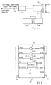
- a secure housing indicated by outline 10 contains electronic circuits 11 including a microprocessor for carrying out accounting functions on data held in registers 28 and data input by means of a keyboard 24.
- a display 27 is provided for the display of data input on the keyboard and for providing operational and instruction data to a user.
- Such circuitry is known in the art of franking machines.
- the registers include a descending register for available credit and an ascending register for the total accumulated usage of franking. These registers are duplicated to provide assurance that the data stored therein is error free and in addition further duplication of the registers may be provided to ensure correct data storage in the event of mal-function of any register.
- the registers also include a register for storing a transaction code.
- the circuitry 11 also carries out control functions and provides print element setting signals to set printing elements of a printer unit (not shown) of the franking machine to the value of franking keyed into the keyboard.
- the circuit generates a print initiation signal to cause operation of the printing elements when a franking operation has been validated.
- a multi-way connector 12 is provided in a wall of the housing 10.
- the connector 12 has a plurality of contacts to provide connections for input signals and output signals.
- the connector may provide a first set of three contacts for lines I1, I2, I3 for input signals and a second set of three contacts for lines O1, O2, O3 for output signals.
- Additional contacts VCC, VDD and GND are used to provide supply potentials of, say, 5 volts and ground potential.
- the contacts of the connector 12 are connected to the circuits 11 of the franking machine by means of interface circuits 13. Connections to all the contacts, apart from that connected to ground potential, include high voltage protection circuits 14. These protection circuits prevent unauthorised or inadvertent application of damaging voltages to the internal circuits of the franking machine from the contacts of the connector 12.
- the protection circuits may include a spark gap and a "Tranzorb" each connected between the contact and ground to protect the franking machine from voltages in excess of 12 volts and a zener diode to provide protection against lower voltages in the range of 5.6 volts to 12 volts. Protection against excessive current flow in the connection is provided by means of a fuse.
- the 5 volt potential is provided from the internal power supply of the franking machine via a semiconductor switch 15 controlled to connect the 5 volt potential to the contact of the connector 12 only when an external device connected to the connector is enabled by control signals from the franking machine circuits 11.
- an independent source of potential may be provided which, if the current demand is low, may be a battery.
- the interface circuits 13 include signal buffering 16 for data and control signals to and from and clock signals from the circuitry 11 of the franking machine. This buffering is achieved by means of open collector gates. In a practical implementation, these signals share a bus to the microcontroller in the circuits 11 with signals for the display and control functions. Therefore the signals to and from the interface circuits 13 time share the bus with the internal signals of the franking machine. Accordingly the signal buffering 16 is enabled for the allocated time share period.
- each of the lines I1, I2, I3 and the lines O1, O2, O3 during a communication with another device is configured by operation of an internal control system of the franking machine in dependence upon the communication standard utilised by the other device. If the device connected to the franking machine operates to the RS232 standard, the input and output lines are configured to conform to that standard. For example, the line O1 will be allocated the function of "transmit data" (TXD), I1 will be allocated the function of "receive data” (RXD), the line O2 will be allocated the function of "data terminal ready” (DTR) and if desired the line I2 will be allocated the function "ready to send” (RTS).
- TXD transmit data
- RXD receiveive data
- DTR data terminal ready
- RTS ready to send
- the lines are allocated functions appropriate to the required standard.
- the configuration of the general purpose port also defines the data speed and characteristics of the lines.
- the operation of the internal control system is controlled by a user of the franking machine by input on the keyboard 24.
- the control circuitry 11 includes a non-volatile memory 25 which has stored therein data for configuring the lines of the communication port to each of a number of selectable communication standards.
- the input on the keyboard by the user of a desired mode of operation or function of the franking machine causes the accounting and control circuitry to access the memory 25 to effect configuration of the general purpose port to the communication standard associated with that selected operation or function of the machine.
- the memory 25 may be utilised to store variable codes related to different modes of operation of the franking machine and the configuration of the port required for those modes of operation.
- a modem 17 to enable communication of data via the telephone network 18 may be connected as shown in Figure 2.
- the modem may be connected by a multi-way cable to the connector 12 or the modem may be constructed integrally with a connector for direct connection to the connector 12.
- Commonly available modems utilise a so-called RS232 interface standard for connection to other devices.
- a converter 19 such as that shown in Figure 3 would be provided for conversion to and from the signal levels of RS232.
- the RS232 standard utilises a 25 way D-type connector 31 of which pin number 2 carries transmitted data (TXD) to a peripheral device, pin number 3 carries received data (RXD) from the peripheral device and pin number 20 carries a data terminal ready signal (DTR) to the peripheral device. Pin number 7 is connected to ground.
- TXD transmitted data
- RXD received data
- DTR data terminal ready signal
- a suitable semi-conductor device which is available on the market and includes the required buffer devices requires power supplies of +10 volts and -10 volts whereas the potential available from the franking machine is only +5 volts.
- the converter 19 includes a DC to DC converter 22 operating from the +5 volt supply to provide the required +10 and -10 volt supplies.
- the modem may be constructed to provide the required signals for direct connection to the signal input and output connections of the franking machine.
- RS422 interface standards
- TXD transmitted data
- RXD received data
- RXD received data
- RXD received data
- Signal buffers 23 are provided to convert the signals on pins 9 and 11 to a data input signal for the franking machine and to convert the data output signal from the franking machine to the transmitted data (TXD) and its inverse ( TXD ) on pins 2 and 4.
- a converter which connects directly to the connector 12 may be provided with a number of interfaces for conversion between the different standards respectively and the signal input and output of the franking machine.
- a further form of converter which may be utilised for connection to the connector 12 is one which receives and transmits optical signals along optical fibres and contains electro-optic converters to convert the optical signals to electrical signals and vice versa.
- the data When secure data is to be received on one of the signal input lines of the connector 12, the data is received in encrypted form and the accounting and control circuit 11 is caused by an instruction input on the keyboard or from an external device via the connector 12 to operate under the steps of a stored program to decrypt the input code, validate the data and then carry out an operation such as adding the new credit represented by the received data to the credit currently registered in the descending register.
- data may be read from a register and after encryption be transmitted via one of the signal output lines of connector 12.
- the contacts of the connector 12 may be connected to any remote device by connecting an appropriate converter or modem to the connector 12. Alternatively the contacts may be connected to the storage device of a portable member if such a member is plugged into the connector 12. Clock signals and, if required, control signals may be output on others of the output lines to control the reading and writing of data in the portable member.
- the accounting and control circuit 11 When non-secure data is to be received or transmitted by way of the connector 12, the accounting and control circuit 11 is instructed by keying an appropriate instruction on the keyboard or by an instruction received via the connector 12 from an external device to cause the accounting and control circuit to operate under the steps of a stored program to, for example, receive signals from a weighscale and input these as a franking value instead of values input by the keyboard. Similarly other input instructions will cause the accounting and control device to transmit selected data to other devices connected to the connector 12.
- the connector 12 may have further contacts providing connections for a current loop data transmission.
- the interface circuits 13 include an electro-optic coupler energised by received data on the loop to generate a data input signal to the circuits 11. Data output from the circuits 11 is transmitted to the loop by means of a switching transistor.
- the input and output lines respectively from and to the connector 12 for input and output signals such as data and clock and/or control signals may be enabled by appropriate enabling of the gates of the signal buffering 16 of the interface circuits 13 by means of control signals.
Landscapes
- Physics & Mathematics (AREA)
- General Physics & Mathematics (AREA)
- Engineering & Computer Science (AREA)
- Theoretical Computer Science (AREA)
- General Engineering & Computer Science (AREA)
- Communication Control (AREA)
- Devices For Checking Fares Or Tickets At Control Points (AREA)
Claims (6)
- Machine à affranchir pour l'affranchissement d'articles de courrier, comprenant des moyens électroniques (11) pour effectuer des fonctions de comptabilité relatives à l'utilisation de la machine dans les opérations d'affranchissement ; des registres de stockage (28) branchés aux moyens électroniques pour stocker des enregistrements de compte ; les moyens électroniques répondant à des signaux de commande pour effectuer des fonctions indiquées par ces signaux de commande ; un boîtier de sécurité (10) contenant de façon sécurisée les moyens électroniques (11) et les registres de stockage (28) ; une prise de communications (12) traversant une paroi du boîtier, à laquelle on peut brancher un dispositif périphérique extérieur à la machine à affranchir, pour assurer les communications avec les moyens électroniques ; caractérisée en ce que la prise de communication (12) est une prise à application générale à laquelle on peut brancher n'importe lequel d'une pluralité de dispositifs périphériques (19, 29) ; en ce qu'une pluralité de connexions électriques (I, O, VCC, VDD) branchent une pluralité de contacts du connecteur (12) aux moyens électroniques (11), un groupe de ces contacts (I, O) présentant des fonctions de transport de signaux déterminées par les moyens électroniques (11) ; ces moyens électroniques fonctionnant en réponse à un signal de commande indiquant une fonction à effectuer, pour déterminer si la fonction indiquée nécessite la transmission des signaux par la prise à application générale et par l'un, spécifique, de la pluralité des dispositifs périphériques avec lesquels la communication doit être effectuée et, en réponse à la détermination que la fonction indiquée nécessite la transmission des signaux par la prise à application générale avec l'un, spécifié, de la pluralité de dispositifs périphériques, pour régler la fonction de transport de signaux des contacts (I, O) du groupe, de manière à déclencher la transmission des signaux par la prise à application générale (12) afin que ces signaux aillent vers le dispositif périphérique spécifié (19, 29) et reviennent de celui-ci.
- Machine à affranchir selon la revendication 1, caractérisée en outre par des moyens de mémoire (25) pour stocker les fonctions de transport de signaux des contacts (I,O) nécessaires pour la communication avec au moins un dispositif périphérique, et en ce que les moyens électroniques (11) accèdent aux moyens de mémoire (25) pour déterminer les fonctions de transport de signaux requises des contacts.
- Machine à affranchir selon l'une des revendications 1 ou 2, caractérisée en outre en ce que les contacts d'un premier sous-groupe (O) du groupe de contacts, sont affectés au transport des signaux sortant des moyens électroniques (11), et en ce que les contacts d'un second sous-groupe (I) des contacts, sont affectés au transport des signaux entrant dans les moyens électroniques (11), ces moyens électroniques fonctionnant en réponse au signal de commande pour déterminer la fonction de transport de signal de chaque contact dans chacun des sous-groupes.
- Machine à affranchir selon l'une des revendications 1, 2 ou 3, caractérisée en outre par des moyens de conversion de signaux (19) branchés de manière amovible au connecteur.
- Machine à affranchir selon la revendication 4, caractérisée en outre en ce que les signaux d'entrée et de sortie des lignes d'entrée et de sortie (I,O) de la prise à application générale (12) présentent un premier niveau qui diffère d'un second niveau de signaux suivant le standard de communication dans lequel la prise à application générale est configurée, et en ce que les moyens de conversion de signaux (19) comprennent des moyens de conversion de niveau de signal (21, 23) fonctionnant pour convertir les signaux à l'un des premier et second niveaux, en signaux présentant l'autre des premier et second niveaux.
- Machine à affranchir selon l'une quelconque des revendications précédentes, caractérisée en outre par une source de puissance et par des moyens de commutation (15) manoeuvrables sélectivement pour brancher la source à l'un des contacts (VCC, VDD) du connecteur (12) de la prise à application générale, et en ce que les moyens électroniques (11) fonctionnent en réponse à la détermination de la communication avec un dispositif périphérique nécessitant de la puissance de la source, pour faire fonctionner les moyens de commutation (15) de manière à appliquer la puissance à ce contact.
Applications Claiming Priority (2)
| Application Number | Priority Date | Filing Date | Title |
|---|---|---|---|
| GB8708031 | 1987-04-03 | ||
| GB878708031A GB8708031D0 (en) | 1987-04-03 | 1987-04-03 | Franking machine |
Publications (3)
| Publication Number | Publication Date |
|---|---|
| EP0285390A2 EP0285390A2 (fr) | 1988-10-05 |
| EP0285390A3 EP0285390A3 (en) | 1989-09-06 |
| EP0285390B1 true EP0285390B1 (fr) | 1994-06-08 |
Family
ID=10615200
Family Applications (1)
| Application Number | Title | Priority Date | Filing Date |
|---|---|---|---|
| EP19880302823 Expired - Lifetime EP0285390B1 (fr) | 1987-04-03 | 1988-03-30 | Machine à affranchir |
Country Status (3)
| Country | Link |
|---|---|
| EP (1) | EP0285390B1 (fr) |
| DE (1) | DE3889965T2 (fr) |
| GB (1) | GB8708031D0 (fr) |
Cited By (6)
| Publication number | Priority date | Publication date | Assignee | Title |
|---|---|---|---|---|
| EP0367284A2 (fr) * | 1988-11-04 | 1990-05-09 | Tektronix Inc. | Porte de sortie reconfigurable |
| WO1993015465A1 (fr) * | 1992-01-31 | 1993-08-05 | Cabletron Systems, Inc. | Interface de supports d'information, configurable par l'utilisateur, pour produits informatiques de reseau |
| US5664123A (en) * | 1994-09-06 | 1997-09-02 | Pitney Bowes Inc. | Digital communication I/O port |
| US5726894A (en) * | 1995-12-21 | 1998-03-10 | Pitney Bowes Inc. | Postage metering system including means for selecting postal processing services for a sheet and digitally printing thereon postal information pertaining to each selected postal processing service |
| US5737426A (en) * | 1994-12-13 | 1998-04-07 | Pitney Bowes Inc. | Remote and secure feature enabling for an electronic postage meter |
| US5926506A (en) * | 1995-11-13 | 1999-07-20 | Francotyp-Postalia Ag & Co. | Method and apparatus for automatically recognizing a modem type of a modem connected to terminal equipment and for automatically adapting the terminal equipment to the recognized modem type |
Family Cites Families (6)
| Publication number | Priority date | Publication date | Assignee | Title |
|---|---|---|---|---|
| US4466079A (en) * | 1981-02-17 | 1984-08-14 | Pitney Bowes Inc. | Mailing system peripheral interface with communications formatting memory |
| JPS5876938A (ja) * | 1981-10-15 | 1983-05-10 | コンバ−ジエント・テクノロジ−ズ・インコ−ポレ−テツド | 異なる入出力プロトコル間の入出力デイジタル回路を構成するための装置と方法 |
| US4506329A (en) * | 1982-03-08 | 1985-03-19 | Pitney Bowes Inc. | Non-volatile memory serial number lock for electronic postage meter |
| US4524426A (en) * | 1983-04-19 | 1985-06-18 | Pitney Bowes Inc. | Electronic postage meter controllable by mailing machine |
| US4642791A (en) * | 1983-09-15 | 1987-02-10 | Pitney Bowes Inc. | Interface for mailing system peripheral devices |
| GB2173741B (en) * | 1985-04-17 | 1989-07-05 | Pitney Bowes Inc | Unsecured postage applying system and method |
-
1987
- 1987-04-03 GB GB878708031A patent/GB8708031D0/en active Pending
-
1988
- 1988-03-30 DE DE19883889965 patent/DE3889965T2/de not_active Expired - Fee Related
- 1988-03-30 EP EP19880302823 patent/EP0285390B1/fr not_active Expired - Lifetime
Cited By (7)
| Publication number | Priority date | Publication date | Assignee | Title |
|---|---|---|---|---|
| EP0367284A2 (fr) * | 1988-11-04 | 1990-05-09 | Tektronix Inc. | Porte de sortie reconfigurable |
| EP0367284A3 (fr) * | 1988-11-04 | 1990-12-05 | Tektronix Inc. | Porte de sortie reconfigurable |
| WO1993015465A1 (fr) * | 1992-01-31 | 1993-08-05 | Cabletron Systems, Inc. | Interface de supports d'information, configurable par l'utilisateur, pour produits informatiques de reseau |
| US5664123A (en) * | 1994-09-06 | 1997-09-02 | Pitney Bowes Inc. | Digital communication I/O port |
| US5737426A (en) * | 1994-12-13 | 1998-04-07 | Pitney Bowes Inc. | Remote and secure feature enabling for an electronic postage meter |
| US5926506A (en) * | 1995-11-13 | 1999-07-20 | Francotyp-Postalia Ag & Co. | Method and apparatus for automatically recognizing a modem type of a modem connected to terminal equipment and for automatically adapting the terminal equipment to the recognized modem type |
| US5726894A (en) * | 1995-12-21 | 1998-03-10 | Pitney Bowes Inc. | Postage metering system including means for selecting postal processing services for a sheet and digitally printing thereon postal information pertaining to each selected postal processing service |
Also Published As
| Publication number | Publication date |
|---|---|
| DE3889965D1 (de) | 1994-07-14 |
| DE3889965T2 (de) | 1994-12-15 |
| GB8708031D0 (en) | 1987-05-07 |
| EP0285390A2 (fr) | 1988-10-05 |
| EP0285390A3 (en) | 1989-09-06 |
Similar Documents
| Publication | Publication Date | Title |
|---|---|---|
| US5206812A (en) | Franking machine | |
| CA1258916A (fr) | Dispositif de detection des impressions falsifiees dans un systeme d'impression d'affranchissement | |
| US5323323A (en) | Franking machine system | |
| US4301507A (en) | Electronic postage meter having plural computing systems | |
| US5688056A (en) | Method for controlling a printer in order to obtain postages | |
| US5490077A (en) | Method for data input into a postage meter machine, arrangement for franking postal matter and for producing an advert mark respectively allocated to a cost allocation account | |
| US5243654A (en) | Metering system with remotely resettable time lockout | |
| US5920850A (en) | Metering system with automatic resettable time lockout | |
| JPS6258388A (ja) | 値印刷装置及びその方法 | |
| US5526271A (en) | Franking machine | |
| CA1223361A (fr) | Compteur electronique d'affranchissement commande par machine de traitement de plis postaux | |
| CA1180120A (fr) | Machine a affranchir electronique avec indicateur de faiblesse de memoire | |
| GB2063163A (en) | Electronic postage meter having field resettable control values | |
| EP0099571B1 (fr) | Boîte pour dispositif électronique tel qu'une machine à affranchir | |
| US4422148A (en) | Electronic postage meter having plural computing systems | |
| US4636975A (en) | Controlling firmware branch points in an electronic postage meter | |
| US4549281A (en) | Electronic postage meter having keyboard entered combination for recharging | |
| EP0285390B1 (fr) | Machine à affranchir | |
| EP0298776B1 (fr) | Système de machine à affranchir | |
| US4584647A (en) | Electronic postage meter with a ring counter | |
| CA1150840A (fr) | Machine d'affranchissement postal pouvant effectuer des operations arithmetiques | |
| US4498187A (en) | Electronic postage meter having plural computing systems | |
| US4525786A (en) | Electronic postage meter having a one time actuable operating program to enable setting of critical accounting registers to predetermined values | |
| EP0356052B1 (fr) | Machine à affranchir | |
| US5613007A (en) | Portable thermal printing apparatus including a security device for detecting attempted unauthorized access |
Legal Events
| Date | Code | Title | Description |
|---|---|---|---|
| PUAI | Public reference made under article 153(3) epc to a published international application that has entered the european phase |
Free format text: ORIGINAL CODE: 0009012 |
|
| AK | Designated contracting states |
Kind code of ref document: A2 Designated state(s): DE FR GB |
|
| PUAL | Search report despatched |
Free format text: ORIGINAL CODE: 0009013 |
|
| AK | Designated contracting states |
Kind code of ref document: A3 Designated state(s): DE FR GB |
|
| 17P | Request for examination filed |
Effective date: 19900220 |
|
| 17Q | First examination report despatched |
Effective date: 19920117 |
|
| RAP1 | Party data changed (applicant data changed or rights of an application transferred) |
Owner name: NEOPOST LIMITED |
|
| GRAA | (expected) grant |
Free format text: ORIGINAL CODE: 0009210 |
|
| AK | Designated contracting states |
Kind code of ref document: B1 Designated state(s): DE FR GB |
|
| ET | Fr: translation filed | ||
| REF | Corresponds to: |
Ref document number: 3889965 Country of ref document: DE Date of ref document: 19940714 |
|
| PLBE | No opposition filed within time limit |
Free format text: ORIGINAL CODE: 0009261 |
|
| STAA | Information on the status of an ep patent application or granted ep patent |
Free format text: STATUS: NO OPPOSITION FILED WITHIN TIME LIMIT |
|
| 26N | No opposition filed | ||
| REG | Reference to a national code |
Ref country code: GB Ref legal event code: IF02 |
|
| PGFP | Annual fee paid to national office [announced via postgrant information from national office to epo] |
Ref country code: FR Payment date: 20060313 Year of fee payment: 19 |
|
| PGFP | Annual fee paid to national office [announced via postgrant information from national office to epo] |
Ref country code: DE Payment date: 20060314 Year of fee payment: 19 |
|
| PGFP | Annual fee paid to national office [announced via postgrant information from national office to epo] |
Ref country code: GB Payment date: 20060322 Year of fee payment: 19 |
|
| GBPC | Gb: european patent ceased through non-payment of renewal fee |
Effective date: 20070330 |
|
| REG | Reference to a national code |
Ref country code: FR Ref legal event code: ST Effective date: 20071130 |
|
| PG25 | Lapsed in a contracting state [announced via postgrant information from national office to epo] |
Ref country code: DE Free format text: LAPSE BECAUSE OF NON-PAYMENT OF DUE FEES Effective date: 20071002 |
|
| PG25 | Lapsed in a contracting state [announced via postgrant information from national office to epo] |
Ref country code: GB Free format text: LAPSE BECAUSE OF NON-PAYMENT OF DUE FEES Effective date: 20070330 |
|
| PG25 | Lapsed in a contracting state [announced via postgrant information from national office to epo] |
Ref country code: FR Free format text: LAPSE BECAUSE OF NON-PAYMENT OF DUE FEES Effective date: 20070402 |