EP0285307A1 - Système pour mesurer le contenu corpusculaire d'un liquide, par exemple le sang - Google Patents
Système pour mesurer le contenu corpusculaire d'un liquide, par exemple le sang Download PDFInfo
- Publication number
- EP0285307A1 EP0285307A1 EP88302511A EP88302511A EP0285307A1 EP 0285307 A1 EP0285307 A1 EP 0285307A1 EP 88302511 A EP88302511 A EP 88302511A EP 88302511 A EP88302511 A EP 88302511A EP 0285307 A1 EP0285307 A1 EP 0285307A1
- Authority
- EP
- European Patent Office
- Prior art keywords
- light
- fluid
- optical
- fiber
- remote
- Prior art date
- Legal status (The legal status is an assumption and is not a legal conclusion. Google has not performed a legal analysis and makes no representation as to the accuracy of the status listed.)
- Granted
Links
Images


Classifications
-
- A—HUMAN NECESSITIES
- A61—MEDICAL OR VETERINARY SCIENCE; HYGIENE
- A61B—DIAGNOSIS; SURGERY; IDENTIFICATION
- A61B5/00—Measuring for diagnostic purposes; Identification of persons
- A61B5/145—Measuring characteristics of blood in vivo, e.g. gas concentration, pH value; Measuring characteristics of body fluids or tissues, e.g. interstitial fluid, cerebral tissue
- A61B5/14535—Measuring characteristics of blood in vivo, e.g. gas concentration, pH value; Measuring characteristics of body fluids or tissues, e.g. interstitial fluid, cerebral tissue for measuring haematocrit
-
- A—HUMAN NECESSITIES
- A61—MEDICAL OR VETERINARY SCIENCE; HYGIENE
- A61B—DIAGNOSIS; SURGERY; IDENTIFICATION
- A61B5/00—Measuring for diagnostic purposes; Identification of persons
- A61B5/145—Measuring characteristics of blood in vivo, e.g. gas concentration, pH value; Measuring characteristics of body fluids or tissues, e.g. interstitial fluid, cerebral tissue
- A61B5/1455—Measuring characteristics of blood in vivo, e.g. gas concentration, pH value; Measuring characteristics of body fluids or tissues, e.g. interstitial fluid, cerebral tissue using optical sensors, e.g. spectral photometrical oximeters
- A61B5/1459—Measuring characteristics of blood in vivo, e.g. gas concentration, pH value; Measuring characteristics of body fluids or tissues, e.g. interstitial fluid, cerebral tissue using optical sensors, e.g. spectral photometrical oximeters invasive, e.g. introduced into the body by a catheter
-
- G—PHYSICS
- G01—MEASURING; TESTING
- G01N—INVESTIGATING OR ANALYSING MATERIALS BY DETERMINING THEIR CHEMICAL OR PHYSICAL PROPERTIES
- G01N21/00—Investigating or analysing materials by the use of optical means, i.e. using sub-millimetre waves, infrared, visible or ultraviolet light
- G01N21/84—Systems specially adapted for particular applications
- G01N21/85—Investigating moving fluids or granular solids
- G01N21/8507—Probe photometers, i.e. with optical measuring part dipped into fluid sample
Definitions
- This invention relates generally to optical catheter systems used for measuring properties of materials in suspension in fluids. It relates more particularly to diagnostic cardiovascular catheters which are used for short-term diagnoses, and which include optic fibers -- whose polished tips are immersed in a patient's bloodstream -- for reflectometric assays of blood characteristics.
- the tips of the optic fibers are usually positioned in the patient's right ventricle or pulmonary artery. At those locations nearly all the blood circulating in the body is collected and well mixed for return to the lungs. Consequently the conditions (such as oxygen-saturation level) there represent by definition a good average of venous conditions for the whole body.
- short term we mean brief periods such as minutes or hours. Much longer usages, such as months or years, characterize a very different type of device -- a so-called “permanent” implant, often part of a pacemaker system.
- Cardiovascular catheters that include optic fibers are well known for short-term measurement of blood-oxygen saturation. Notable United States patents in this area are 4,295,470, 4,114,604 and 3,847,483 to Shaw et al. , and 4,523,279 and 4,453,218 to Sperinde et al. These systems generally project light of two or three different wavelengths into the blood.
- the blood differentially reflects the light components of different wavelengths, and the difference -- or preferably the ratio -- of reflectances varies with the level of oxygen saturation in the blood. Consequently the reflectance ratio can be used as a measure of oxygen saturation.
- Shaw resolves this and other uncontrolled influences by introducing and detecting light of a third wavelength: this technique provides enough information to correct the oxygen measurement for the unknown effects. Such a refinement is of course very useful, but relatively cumbersome in requiring three different light sources.
- the Schmitt et al. system incorporates implantable transducers positioned directly at the measurement site, within the patient's body. There is no optic fiber; rather, any necessary light source(s) and detector(s) are exposed directly to the patient's bloodstream. The system does measure both oxygen concentration and hematocrit.
- the paper also suggests that the ratio of intensities detected at two different source/detector distances might be used to determine hematocrit, independent of oxygen saturation.
- the paper discloses no particular configuration for doing so.
- the Schmitt system has the disadvantages of very extreme costliness and fragility. Production and assembly techniques for such devices, as described by Schmitt et al. , are extremely awkward and difficult.
- the Schmitt group found it necessary to assemble the various elements of their device (including an integrated-circuit controller) on a silicon wafer, and then to encapsulate it. As will readily be appreciated by those skilled in the art, such procedures are among the most demanding and expensive of all industrial techniques.
- the finished Schmitt device is an elaborate wafer-mounted transducer array, hermetically sealed with solder connections and so forth.
- Each optical transducer made by the Schmitt approach accordingly runs into the hundreds of dollars, at the present (1986) monetary scale.
- cardiovascular catheters or, indeed, catheters of any type, or for that matter any other device that is immersed in blood, or cardiovascular expeditions by any technique.
- Their invention is, however, an optical device for determining blood-oxygen saturation -- and a parameter that is analogous to hematocrit as well.
- the Donahoe system is a reflectance oximeter that is applied to external surfaces of the patient's body. It includes a light source that, in use, is positioned directly against the patient's body tissue, so that light from the source passes directly into the tissue.
- the system receives light that is backscattered by the tissue itself and also by whatever blood is present within the tissue.
- the device receives the scattered light at two separated detectors, both also positioned directly against the patient's body tissue -- so that light passes directly from the tissue into the detectors.
- tissue hematocrit volume of blood corpuscles per unit volume of body tissue .
- the 1984 Schmitt system provides such measurements, but at prohibitive cost.
- the 1985 Donahoe system provides only analogous measurements, for the periphery of the body.
- the Schmitt group reports measurement variation of "about 19%" (root-mean-square deviation). That value is an order of magnitude too large for state-of-the-art medical practice.
- Schmitt's optical-sensor package was six millimeters long, two millimeters wide and one millimeter thick. Although the authors believed it "possible" to reduce the width to about one millimeter, even with such a reduction the package would be much too large to fit on the tip of a cardiovascular catheter for use in human beings.
- Our invention is a system for determining the corpuscular content of a fluid that contains a varying quantity of corpuscles. It includes some means for emitting light, and some means for detecting light.
- Both the light-emitting and the light-detecting means are remote from the fluid of interest.
- the fluid may be blood in a patient's pulmonary artery, and the emitting and detecting means may be in an equipment module that is just outside the patient's body.
- Our invention is amenable, however, to implementation over considerably longer distances in other applications.
- Our invention also requires some means for transmitting light from the remote light-emitting means by way of the fluid under test to the remote light-detecting means. It is quite important to our invention that this light transmission occurs along two paths -- usually parallel paths. In accordance with our invention, these means for transmitting light must include one or more optical fibers; hence we shall call these means the "optical-fiber means.”
- Each of the two paths provided by the optical-fiber means includes three segments. There is a first optical-fiber-means segment for directing light from the remote emitting means to the fluid. This first segment terminates in light-projecting means that are disposed adjacent to the fluid.
- each of the two paths there is a second optical-fiber-means segment for directing light from the fluid to the remote detecting means.
- This second segment commences in light-receiving means that are disposed adjacent to the fluid.
- each path there is also a third segment, between the light-projecting and light-receiving means, that includes scattering by the fluid and by any corpuscles that are within that fluid.
- at least part of each third segment passes at least shallowly through the fluid.
- the first segment and its light-projecting means for one of the two paths have a first fixed, known geometrical relationship to the second segment and its light-receiving means for that one path.
- first segment and its light-projecting means for the other of the two paths have a second fixed, known geometrical relationship to the second segment and its light-receiving means for that other path. It is particularly important that the second geometrical relationship be different from the first.
- the third segments that is, the segments that include scattering within the fluid -- are made different for the two paths.
- This difference between the third segments offers a means of measuring corpuscular concentrations of the fluid.
- our invention includes some means for comparing the light respectively transmitted along the two paths to determine the quantity of corpuscles. These means, which we will call the “interpretation means,” are responsive to the light-detecting means; and in their operation they take into consideration the two known, different geometrical relationships.
- optical-fiber-means path segments may be distinct, discrete subpaths; or one of the optical-fiber-means segments may be used by both paths in common.
- the other variant is the reverse -- two sources, and two "first segments” directing light into the fluid; and a single "second segment” with corresponding detector used in common for the return.
- the distinct optical-fiber-means segments use a common source or detector, but the effects of propagation along different paths are separated from one another in time or in frequency by -- for example -- alternate chopping or other modulation schemes.
- the common source or detector in effect serves as two distinct sources or detectors.
- the three or four physically discrete optical-fiber-means path segments may be separated from one another by being in discrete fibers; or it is also possible that two or more may share a single fiber.
- any of these several forms of our invention may be greatly enhanced by provision of additional elements enabling the system to measure also the chemical content of the fluid.
- spectral effects can be used to determine oxygen saturation of the blood, using either one of the two paths from source to detector.
- Our invention has broad utility. Its embodiments of greatest current interest to us, however, are all in the area of cardiovascular diagnostic systems.
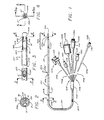
- the preferred embodiment of our invention makes use of a fiver-lumen catheter 101. It will be understood that our present invention can instead be implemented in a catheter having more or fewer lumens, or even only one lumen, but we believe that the full potential of the invention is best realized in a multiple-function catheter generally as described below.
- the catheter diameter is preferably 7.5 French or less.
- a manifold connector 105 Fixed at the proximal end of the catheter 101 are a manifold connector 105 and five individual single-lumen tubes 106. These individual tubes respectively communicate at their distal ends with the five lumens T/F, P, B, D, and P/M of the catheter 101 -- through the manifold connector 105 -- and at their proximal ends with five termination devices 107.
- a molded tip 102 and an annular balloon 104 Fixed at the distal end of the catheter 101 are a molded tip 102 and an annular balloon 104.
- a port of aperture D ⁇ (Fig. 4).
- This distal aperture D ⁇ effectively constitutes the distal end of one of the lumens D (Fig. 2) in the catheter 101.
- the remaining space in the orifice of the tip is occupied with epoxy or like inert potting material 136.
- a catheter of this sort is inserted through the patient's vena cava into the right atrium and ventricle, with the tip 103 and its distal aperture D ⁇ extending onward into the pulmonary artery.
- the tip 103 generally is held in that artery for pressure measurements and optical measurements.
- the arrangement of the polished ends of the optic fibers at F ⁇ appears in Figs. 4, 5 and particularly 5a. As there suggested, the optic fibers are mutually aligned side-by-side and parallel in a linear array.
- Fig. 5 The longitudinal section of Fig. 5 is taken through the spacer rr shown in Fig. 5a. This configuration is preferred for reasons to be set forth.
- one fiber nn to transmit light from a single source to the fluid under test
- two other fibers oo and pp to transmit backscattered light from the fluid to two separate detectors.
- the ends of the two other fibers oo and pp are differentially spaced -- by an optically inactive fiber piece rr -- from the end of the first fiber nn .
- the spacer rr could be of entirely different size and cross-sectional shape -- e. g. , square, rectangular, or in any of a great variety of elaborate forms.
- the space 533 below the spacer rr may be filled with a suitable adhesive material.
- the bottom end of the spacer rr may be tapered to minimize the amount of space to be so filled.
- Figs. 5 and 5a, and particularly Fig. 4 can also be taken as representing yet another above-discussed system in which two fibers nn and oo transmit light from separate sources, and two fibers pp and qq (not visible, implicitly out of the plane of the paper behind or in front of pp ) return backscattered light from those separate sources to corresponding separate detectors.
- Light from the separate sources can be distinguished as by time multiplexing.
- Our invention uses the hematocrit dependence to develop a hematocrit measurement signal.
- a hematocrit measurement signal is subject to variations due to source fluctuations, variations in the transmissive quality of optic fibers and particularly the condition of their tips, and also in optical qualities of the blood itself.
- one detector fiber pp (and its associated detector) may be regarded as the primary signal path, while a reference signal is in effect obtained from the other detector fiber oo (and its detector).
- either fiber could be regarded as the reference detector. Since, however, the optical signal in the fiber pp that is farther from the source fiber nn is more strongly dependent on hematocrit than the optical signal in the nearer fiber oo , we prefer the nomenclature established in the preceding paragraph.
- the hematocrit measurement obtained with our invention requires light at only one wavelength -- and, in particular, light at the isobestic wavelength that is generally used to compute oxygen saturation of blood.
- our invention can be used without any additional light source to obtain and read out an independent measurement of hematocrit -- and then to correct oxygen-saturation measurements for the hematocrit level.
- the independent hematocrit readout is of value to the practicing clinician.
- the prior art only corrects oxygen saturation for hematocrit without independently determining and reading out the hematocrit value.
- the balloon 104 is formed as a short length of latex tubing, positioned over a necked-down end section 131 of the catheter 101.
- the distal end of the balloon tubing 104 is doubled under and is held by adhesive 501 to the neck portion 103 of the tip 102.
- the proximal end of the balloon tubing 104 is held by adhesive 135 to the proximal end of the necked-down end section 131, and the tapered annular space just proximal to the balloon is filled with epoxy or like cement 503.
- a very small balloon-inflation aperture B ⁇ is defined in the necked-down end section 131 of the catheter 101, communicating with the dedicated balloon lumen B (Fig. 2).
- an aperture T/F ⁇ (Fig. 1) is formed in the catheter wall, communicating with the lumen T/F (Fig. 2).
- This aperture is occupied principally by a thermistor bead T ⁇ (Fig. 3), functionally connected at the distal end of the thermistor leads T (Fig. 2).
- the remainder of the aperture T/F ⁇ is filled with urethane or like potting compound 137.
- the balloon 104 and thermistor T ⁇ are generally passed with the tip 103 into the patient's pulmonary artery. Temperature information developed with this part of our system thus relates to the blood in that artery. As is well known in the field, such information can be used to monitor passage through that artery of a cold bolus of liquid injected at a known point upstream -- as, for example, in the right atrium.
- the instrumentation can develop data on the pumping capacity of pump flow rate of the heart, usually called “cardiac output.” Accuracy of these data is enhanced by comparing the measure blood temperature with the preinjection temperature of the injectate alone.
- the latter temperature (correspondingly designated T i ) is measured using a separate thermistor, not illustrated.
- the thermistor leads T share the lumen T/F with the optic fibers F.
- the thermistor leads T and optic fibers F should be drawn together through the thermistor-and-fiber lumen T/F. Doing so may have another advantage -- namely, minimizing the risk of damage to both the leads T and the fibers F.
- another aperture P/M ⁇ is formed in the wall of the catheter 101, this one in communication with the lumen P/M.
- This lumen P/M and aperture P/M ⁇ can be left unobstructed, for measurement of pressure in the right ventricle through a fluid column in the lumen; or when desired can be used for heart pacing, as described below.
- a coaxial wire 139 Within the lumen P/M, extending outward from the catheter 101 through the aperture P/M ⁇ is a coaxial wire 139. In use, it is typically positioned in the patient's right ventricle, lying against the myocardium or heart muscle.
- the central conductor of this wire 139 is exposed so that the outer and inner conductors form an electrode pair for application of pacing voltage pulses to the myocardium.
- Unused clearance space within the lumen P/M and its aperture P/M ⁇ can be used for drip administration of medication -- including, for example, dilute heparin solution or other anticoagulant to help maintain the lumen P/M and its aperture P/M ⁇ (Fig. 1) free of blood clots.
- a very short length of stainless-steel spring wire (not shown) is inserted into the lumen P/M. This wire serves to plug the unused, distal portion of this lumen, and also to form a radiopaque marker that can be helpful in positioning the catheter with the aperture P/M ⁇ in the patient's right ventricle for proper pacing.
- this proximal aperture P ⁇ is typically positioned within the patient's right atrium, and is used for injection of a cold bolus in the thermodilution method of cardiac output (flow rate) measurement. This same aperture P ⁇ can also be used to measure pressures.
- a very short rod of solid polyvinyl chloride or the like is inserted into the corresponding lumen P, to block off the unused, distal portion of this lumen.
- markers are advantageously imprinted along the outside of the catheter at suitable intervals.
- indicium 121 may be placed at ten centimeters from the tip 102, indicium 122 at twenty centimeters, and indicium 123 at thirty centimeters.
- Each of these indicia may be a simple narrow band or group of narrow bands, each band representing a cumulative ten centimeters. More than four bands being hard to count quickly, however, it is helpful to use a single broader band for the fifty-centimeter indicium, and then a broad band next to a narrow band to represent fifty-plus-ten or sixty centimeters, etc. Thus the one-hundred centimeter indicium 124 appears as a pair of broad bands.
- Individual termination devices 107 at the proximal end of the catheter include a stopcock 111, communicating with the balloon lumen B, and a first hub or extension port 112 communicating with the distal-aperture lumen D.
- the stopcock 111 is for inflating (or deflating) the balloon 104.
- the port 112 is used for measuring pulmonary-artery pressures or injecting medication into that artery -- or, on a drip basis (as with anticoagulant heparin, at three to six milliliters per hour), both simultaneously.
- the termination devices also include a fiber optic connector 113, connected with the optic fibers F in the thermistor/fiber lumen T/F.
- the polished proximal ends 144 of the fibers F are presented at the proximal side of the connector cap 143 for connection to a mating device (not illustrated) that provides the necessary light sources, detection and interpretation.
- termination devices 107 include an electrical connector 114, which provides connection points for the thermistor leads T.
- a threaded section 146 is advantageously provided at the proximal side of the connector cap 145 to securely engage a mating connector of an electronics module that provides excitation and interpretation for the thermistor T ⁇ .
- the termination devices 107 are two other hubs 115 and 116.
- one port 115 communicates with the proximal lumen P, for injection of a cold bolus in thermodilution cardiac-capacity tests.
- the other port 116 connects with the pacing-and-medication lumen P/M to guide the coaxial pacing wire 139 (and drip medication) to the right ventricle.
- a Touy-Borst connector allows both electrical hookup to the wire and injection of medicine. (If preferred, the pacing wire 139 can be omitted, and instead a fluid column can be established in the lumen P/M for right-ventricle pressure measurement at the port 116.)
- the stopcock 111 and the hub or extension ports 112, 115 and 116 all end in respective liquid-transfer fittings 141, 142, 147 and 148 -- which are adapted for pressurized attachment of hypodermic-style injecting apparatus.
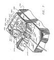
- Fig. 6 Additional details of the termination device 113 for the optic fibers appear in Fig. 6. That drawing also presents added details of the termination device 114 for the thermistor leads. The other intermediate tubulations 106 are drawn broken off at 524.
- the optic-fiber connector 113 As shown in the drawing, we prefer to configure the optic-fiber connector 113 as a formed housing 113a that has three integral sides and an integral distal end, and that also has a cover 113b along a fourth side.
- a stress-relief fitting 523 is provided to minimize the potential for damage to the optic fibers within the fiber bundle 106c.
- the proximal end of the housing 113a is covered by a cap 113c in which are formed three precisely positioned ferrules 521a, 521b and 521c. Firmly secured within these ferrules are proximal optic-fiber tips 522a, 522b and 522c respectively.
- the ferrules 521a, b, c and corresponding fiber tips 522a, b, c may be ground and polished together, to provide good mechanical and optical mating with detection and interpretation apparatus to be described below.
- the ferrules assure adequate lateral alignment of the fiber tips with the detection apparatus.
- these three proximal optic-fiber tips 522a, 522b and 522c are respectively continuous with the three distal optic-fiber ends nn , oo and pp of Figs. 5 and 5a.
- Fig. 7 illustrates generally the mechanical arrangements for optical linkage of the fiber tips 144a, b, c to the emitters and detectors. That drawing illustrates generally a small electronics cabinet 201, for placement beside a patient who is to be catheterized. The interior 259 of the cabinet 201 houses various signal-generating and -processing circuits to be described.
- An auxiliary compartment 22 (drawn broken away at 206) is secured atop one end of the cabinet 201.
- the top panel of the cabinet 201 is apertured at 207 for free access as between the interior 259 of the cabinet and the interior of the auxiliary compartment 202.
- a bulkhead 209 at one end of the auxiliary compartment 202 is apertured at 241 to provide limited access to the interior of the auxiliary compartment.
- An optical-connector receptacle 211 (drawn broken away at 212) is mounted in the aperture 241).
- a formed cover 203 (drawn broken away at 204), hinged to the same bulkhead, protects the receptacle 211 and the area just in front of that receptacle.
- the connector 113 at the proximal end of the optic-fiber termination 106c is mated with the receptacle 211.
- the cover 203 is then lowered to protect the connection --- while a notch 205 in the cover 203 permits the passage of the optical termination 106c.
- receiver segments 244a, 244b and 244c are disposed for alignment with the respective fiber tips 144a, 144b and 144c when the connector 113 is present.
- the receiver segments 244a, b and c have polished distal ends spring-loaded as at 245 toward engagement with the respective fiber tips.
- optical signals pass outward from light emitters toward the catheter through one fiber 246a, and inward from the catheter toward the detectors through the other two fibers 246b and 246c.
- Red and infrared signals in the "outbound" fiber 246a originate in light-emitting diodes DS1 and DS2, respectively excited through electrical-signal leads 255 and 256 from pulse-generating circuitry within the cabinet 201. These optical signals pass from the diodes DS1 and DS2 through respective optic fibers 252 and 253 to a "mixer" section 251a, which combines the signals and passes them on into the fiber 246a.
- the light-emitting diodes DS1 and DS2, the mixer unit 251a, and the combination detector-amplifier-buffer units 251b and 251c are all drawn in combination with their respectively associated optical connectors. All or some of these units may be allowed to "float" ( i. e. , to be suspended by their attached optic fibers and electrical leads) as illustrated.
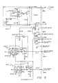
- Fig. 8 represents the active portions of an electrical module to be housed within the cabinet 201.
- the cabinet optionally may also provide through-connections to the thermistor wires, not shown in Fig. 8 -- or if preferred the temperature-signal cabling may be provided separately.
- This module 303 receives regulated positive and negative supply voltage through respective leads 331a and 331b of a shielded cable, for distribution by respective leads 314a and 314b within the patient-side module to a thermal-control unit 313 and to respective ripple filters R13-C1 and R14-C2. From these filters the supply voltages pass to the integrated detector-amplifier units 251b and 251c.
- emitter-excitation signals Passing through the cable 304 in addition to the supply voltages are emitter-excitation signals, in two leads 332 and 333. Within the patient-side module 303 these signals proceed directly via respective leads 315 and 316 to the light-emitting diodes DS1 and DS2. These diodes respectively project the red and infrared signals into optic fibers 252 and 253. These both lead to a common optical mixer 250.
- the thermal-control unit 313 is included to stabilize the temperature of the light-emitting diodes DS1 and DS2. It accordingly stabilizes the intensity and spectral distribution of their emission, which can be significant in achieving adequate photometric accuracy for hematocrit determination -- and very important in achieving adequate spectrometric accuracy for oxygen determination.
- an operational amplifier U1 compares a reference voltage (produced at a temperature-sensitive reference diode U2) with a voltage developed by the resistive divider R5-R6-R7.
- the divider includes the first-stage feedback resistor R5, which directly affects the first-stage gain, and bias resistance consisting of R6 and a sensitive trimming resistor R7.
- the amplifier U1 produces a difference signal which controls the current level in a power transistor Q3.
- This transistor (as well as its load resistor R10) serves as a heater, controlling the temperature of the temperature reference diode U2 and thereby shifting the operating point of the amplifier U1.
- the sense of the shift is such as to oppose changes in the temperature of the resistor string R5-R6-R7.
- the heater also controls and stabilizes the temperature of the diodes DS1 and DS2.
- ripple-filtered power is applied to integrated detector-amplifiers 251b and 251c.
- Each of these units includes an integrated-circuit detector-amplifier Q1 or Q2, each with its own respective light-sensitive diode D1 or D2, a corresponding load resistor R11 or R12, and an amplifier A1 or A2.
- Optical signals in the associated optic fiber 246b or 246c cause conduction in the diode, drawing down slightly the input voltage to the amplifier A1 or A2.
- An amplified version of the diode voltage accordingly appears at the output terminal of the integrated-circuit detector-amplifier Q1 or Q2.
- This amplified Q1 or Q2 output is applied to one stage Q4A or Q4B of an operational amplifier, which is also part of the combination detector-amplifier 251b or 251c.
- Each operational-amplifier stage O4A or O4B is wired in its respective circuit as a cathode follower.
- Each combination detector-amplifier-buffer 251b or 251c thus provides an amplified and buffered "near fiber” or “far fiber” electrical signal on its output lead 317 or 318, for conduction to the main electronics unit by a corresponding conductor 334 or 335 in the cable 304.
- Fig. 9 The functions of the patient-side module 303 also appear more schematically in Fig. 9 in conjunction with the remainder of the circuitry, which is primarily in the main electronics unit 305.
- Other modules such as a printer 306 may be incorporated into the system as appropriate.
- Fig. 9 also shows the optical connector 113-213, and the catheter optical terminations 144a, b and c, which were previously discussed in connection with Fig. 7. Further, Fig. 9 illustrates that the patient-side module 303 may include through-connections 321 and 322 for the thermistor signals; alternatively, we may prefer to provide separate temperature-signal cabling directly from the main electronics unit 305, for one or both of the thermistors.
- through-connections 321 and 322 are wired at one end to an electrical connector 146-346 for the catheter electrical terminations 302. As seen in Fig. 9, the through-connections 321 and 322 are wired at their other end to the previously mentioned connector 323-324, which serves the cable 304 to the main electronics unit 305.
- Fig. 9 is devoted to showing the main electronics unit 305. That unit generates the necessary electrical excitation for production of the optical probe signals -- and interprets the electrical signals returned as a result of the interaction of those probe signals with the blood (or other fluid under test).
- a power supply 352 within the main electronics unit 305 develops positive and negative supply voltages as at 426. These voltages are for distribution to generally all the power-consuming modules within the main electronics unit 305 proper.
- the power supply 352 also provides positive and negative voltages at leads 401 for certain uses that are individually illustrated. These uses include supply of the patient-side module 303, as previously mentioned, via certain leads 331 of its cable 304.
- the individually illustrated use points also include two current switches 353 and 354, and the primaries 421 and 422 of two power-isolation transformers 383 and 385 respectively.
- the current switches 353 and 354 are actuated by control signals at 422 and 423 from an electrical controller 365.
- the switches 353, 354 Under direction of the controller 365, the switches 353, 354 "chop” or time-modulate the excitation signals 402-332-315 and 403-333-316 to the red and infrared light-emitting diodes DS1 and DS2 respectively.
- the switches 353, 354 conduct in alternation, separated by time intervals in which neither switch makes contact.
- the diodes DS1 and DS2 emit alternately, separated by "dark" intervals.
- This modulation pattern thus imposed upon the discrete optical signals through the optic fibers 252 and 253 to the optical mixer 250, of course persists in the composite optical signal through the outbound fibers 246a in the patient-side module 303 and 144a in the catheter 101.
- the modulation enables the signal-interpreting part of the circuitry to sort out the red-absorption data from the infrared-absorption data, and both from the background noise occurring during the "dark" intervals, in the returned signals. That part of the circuit will be discussed shortly.
- controller 265 directs the operation of the current switches 353 and 354, the controller in turn receives "address" information (via part of an address bus 452 ⁇ ) from a microprocessor or "central-processing unit” (CPU) 391, through an address-and-data bus 451 and an address-and-data decoder 392.
- CPU central-processing unit
- the controller 365 is thus in effect an interface between the analog and digital modules or sections of the main electronics unit 305. Analogous specific functions of the controller 365 will be noted below.
- the supply of power at 401 through isolating transformers 383 and 385 is part of a guarding system. This system permits the blood-temperature interface 357 and injectate-temperature module 358 to be electrically isolated or "floating" relative to all the voltages in the entire system.
- the two temperature interface modules are electrically connected to thermistors which in use are disposed within a patient's body, and more particularly within the patient's heart.
- the blood-temperature and injectate-temperature interfaces receive signals from, respectively, a thermistor in the catheter and a thermistor that is in thermal contact with the injectate. As previously outlined, these signals are used in determining cardiac output by the thermal-dilution method.
- the interfaces 357 and 358 receive the thermistor signals via catheter electrical terminations 302 (drawn broken away at 311, 312 in Fig. 9); and via leads 321, 322 in the patient-side module and leads 336, 336 in the cable 304.
- the thermistor signals then enter the isolated interface sections 357 and 358 along leads 409 and 415, passing to respective buffers 381, 386 and thence by signal leads 411, 417 to V/F units 382, 387. These units are powered from the secondaries 406, 413 of the respective isolation transformers 383, 385.
- control signals 424, 425 are supplied by the controller 365, again under direction of the CPU 391 and the address-and-data decoder 392.
- control signals before entering the isolated interface sections 357, 358 are converted to optical signals by electrically energized light sources. Within the isolated sections these optical signals are then reconverted to electrical signals by photodetectors.
- Another source-and-detector pair connected for signal flow in the opposite direction carries the V/F outputs 412, 418 with electrical isolation into the main electronics unit proper. There they are transmitted at 442, 436 to respective amplifiers 366, 367.
- the amplified signals 443, 437 -- with an additional filtering 368 of the injectate signal, to band-limit the signal and thereby prevent "aliasing" during later sampling for analog-to-digital conversion -- are then applied at 443, 441 to a multiplexer 371.
- the multiplexer is synchronized by a signal 435 from the controller, which as for the earlier-mentioned functions is directed by the CPU 391 through the decoder 392.
- the multiplexer 371 produces a single analog output signal 444 that is in effect a composite of the two temperature signals.
- This composite signal 444 proceeds to an analog-to-digital converter (“ADC") 372, which under direct control 446 of the CPU 391 generates a corresponding digital stream.
- ADC digital output passes by an input bus 445 to the CPU 391.
- modulated excitation signals 402, 403 produce modulated red and infrared optical signals in the outbound optic-fiber termination 144a. (Depending on the spectral character of the phenomena to be analyzed in the fluid under test, some other two-wavelength pair of signals may be substituted.)
- the differential scattering produces, in effect, differential attenuation of the red and infrared optical signals by the test fluid.
- Some of the differentially attenuated light within the fluid reaches and enters the distal tips pp , oo (Fig. 5a) of the return fibers.
- optical signals reach the detector-amplifiers 251b and 251c and produce corresponding electrical signals 317 and 318. Still the spectral effects in the optical signals are separable in each of the electrical signals by virtue of the modulation previously imposed on the excitation signals.
- the optical signals also contain differential geometric information. As will be recalled, the latter is used to assess the blood hematocrit -- or, more generally, analogous corpuscular phenomena within any test fluid.
- Hematocrit or analogous particulate properties interact with the differential spatial separation (at the distal end of the catheter) of the receiving-fiber tips pp and oo from the emitting tip nn .
- the interaction permits calculation of hematocrit or the like from a comparison of the optical signals returned from the distal tips.
- the electrical signals 317 and 318 from the patient-side module are kept separate. Respectively, they are identified as a “near-fiber signal” 317 (arising as an optical signal in the distal tip oo , and in the proximal termination 144b) and a “far-fiber signal” 318 (arising in the distal tip pp and the proximal termination 144c).
- the amplified signals are applied to respective "sample and hold" circuits 361 and 362, which are actuated by control signals 431 and 432 from the controller 365.
- the controller 365 is directed by the CPU 391, through the address-and-data decoder 392 as before, to generate the control signals 431, 432, 433. Since the single output signal 434 from the multiplexer 363 contains all the spectral and geometric data, the CPU must time the control signals to preserve all the spectral and geometric data in the electrical signals 404, 405.
- the composite signal 434 from the multiplexer enters an analog-to-digital converter ("ADC") 438, which projects a corresponding digital signal into the data bus 453. This digital signal is directed via the data bus 453 to the CPU 391.
- ADC analog-to-digital converter
- the digital signal from the ADC 438 is also available on the data bus 453 to various other elements of the system. These elements include the display 393, random-access memory (“RAM”) 395, digital-to-analog converter (“DAC”) 396, and printer interface 398.
- RAM random-access memory
- DAC digital-to-analog converter
- the RAM 395 provides temporary storage of any information on the data bus 453. It also reads such data back into the bus on command, for later use.
- the DAC 396 provides an analog equivalent 455 of any signal on the data bus 453 for passage to an auxiliary-output interface 397.
- This interface may be a serial output port for a telemetry connection, or any other appropriate external use.
- the output signal from the printer interface 398 is naturally directed through a connector 343, 344 to an external-printer data bus 454. It is there used for generation of a permanent record by an external printer 306.
- the ADC 438 output can be displayed, stored, telemetered or printed.
- the digital signal from the ADC 438 is not suitable for direct display, storage, printout or other use.
- the ADC 438 output is a composite of both spectral and geometric information -- that is to say, of both oxygenation and hematocrit information, in the case of blood.
- the ADC digital output generally is unintelligible in its "raw” form, and requires further processing in the form of calculations within the CPU 391. It is the results of these calculations are displayed, printed, or stored.
- the system also includes a keyboard 351, a programmable read-only memory (“ROM”) 394, the address-and-data decoder 392, and an address bus 452.
- ROM read-only memory
- An operator uses the keyboard 351 to enter various instrument settings, sample identifications, data-handling directions, and so on. From the keyboard 351 these various kinds of information generally proceed along the data bus 453 to the CPU 391 and in some cases also directly to the display 393 or the RAM 395.
- Permanently stored in the PROM 394 are programs for sequencing of the controller 365 and of the various digital modules 351, 391-398. These programs include, in particular, instructions for internal operation of the CPU 391 to perform the necessary data separation and calculations.
- the decoder 392 and the address bus 452 function in conventional fashion for digital control and computation devices.
- the decoder translates addresses and data as specified by the CPU 391 into a form usable by the other system elements 351, 393-398 and 306.
- the address bus 452 carries the decoded addresses from the decoder 392 to the other system elements. In effect it parallels the data bus 453, identifying the particular memory, display, or other location where each data bit is to be "written” or "read.”
- the program uses the ratios x and r to calculate both hematocrit Hct and oxygen saturation, in the case of blood -- or analogous corpuscular and chemical characteristics in the case of other test fluids.
- a so-called “isobestic" wavelength is a wavelength at which there is no difference between the scattering by oxygenated blood and the scattering by nonoxygenated blood.
- the positive and negative voltage supplies 401 for the patient-side module and to the current switches are advantageously ⁇ 8 volts.
- the supplies 426 are preferably ⁇ 8 and +5 volts.
- the supply 401 to the isolation transformers 383 and 385 preferably includes a four-ampere-hour battery backup, and should be capable of supplying 800 mA through a chopper to the primary windings 421 and 422. Within the isolated sections, if desired the supply voltage may be boosted slightly (by the isolation transformers) to ⁇ 9 volts.
- the CPU 391 is preferably an eight-bit C-MOS type available commercially from the NSC under the model number 800-1.
- the PROM 394 is preferably a 256 k unit, the RAM 395 preferably a 32 k unit, and the optical-channel ADC 438 is preferably a twelve-bit high-speed unit available under the designator ADC 1205.
- the DAC 396 may be an eight-bit unit.
- the auxiliary-output interface is one of the type commercially identified as RS 232, and the display 393 is advantageously a four-line, fourteen-character liquid-crystal device.
- the keyboard 351 should have twenty keys, and the printer 306 may be a thirteen-column, five-by-seven-dot matrix type.
- the red light-emitting diode should provide light at 660 millimicrons, and the infrared diode at 805 millimicrons.
- the patient-side-module cable is advantageously about three meters (ten feet) long.
Applications Claiming Priority (2)
| Application Number | Priority Date | Filing Date | Title |
|---|---|---|---|
| US07/028,756 US4776340A (en) | 1987-03-23 | 1987-03-23 | Hematocrit measurement by differential optical geometry in a short-term diagnostic cardiovascular catheter, and application to correction of blood-oxygen measurement |
| US28756 | 1987-03-23 |
Publications (2)
| Publication Number | Publication Date |
|---|---|
| EP0285307A1 true EP0285307A1 (fr) | 1988-10-05 |
| EP0285307B1 EP0285307B1 (fr) | 1995-03-01 |
Family
ID=21845249
Family Applications (1)
| Application Number | Title | Priority Date | Filing Date |
|---|---|---|---|
| EP88302511A Expired - Lifetime EP0285307B1 (fr) | 1987-03-23 | 1988-03-22 | Système pour mesurer le contenu corpusculaire d'un liquide, par exemple le sang |
Country Status (6)
| Country | Link |
|---|---|
| US (1) | US4776340A (fr) |
| EP (1) | EP0285307B1 (fr) |
| JP (1) | JPS63283627A (fr) |
| AT (1) | ATE119005T1 (fr) |
| DE (1) | DE3853173T2 (fr) |
| ES (1) | ES2068198T3 (fr) |
Cited By (7)
| Publication number | Priority date | Publication date | Assignee | Title |
|---|---|---|---|---|
| EP0471898A1 (fr) * | 1990-08-22 | 1992-02-26 | Nellcor Incorporated | Appareil d'oximètre à impulsion d'un foetus et méthode d'utilisation |
| US5099842A (en) * | 1988-10-28 | 1992-03-31 | Nellcor Incorporated | Perinatal pulse oximetry probe |
| US5109849A (en) * | 1983-08-30 | 1992-05-05 | Nellcor, Inc. | Perinatal pulse oximetry sensor |
| EP0494524A2 (fr) * | 1991-01-10 | 1992-07-15 | Imperial Chemical Industries Plc | Dispositif de surveillance |
| EP0720013A2 (fr) | 1994-12-28 | 1996-07-03 | Coretech Medical Technologies Corporation | L'analyse spectrophotométrique du sang |
| US5551424A (en) * | 1990-05-29 | 1996-09-03 | Phox Medical Optics, Inc. | Fetal probe apparatus |
| EP1125126A1 (fr) * | 1998-11-06 | 2001-08-22 | Medtronic Avecor Cardiovascular, Inc. | Appareil et procede permettant de determiner des parametres sanguins |
Families Citing this family (45)
| Publication number | Priority date | Publication date | Assignee | Title |
|---|---|---|---|---|
| JPH07108284B2 (ja) * | 1986-12-26 | 1995-11-22 | オリンパス光学工業株式会社 | 体外観察装置 |
| EP0311295A3 (fr) * | 1987-10-07 | 1990-02-28 | University College London | Appareils chirurgicaux |
| US5201317A (en) * | 1988-06-06 | 1993-04-13 | Sumitomo Electric Industries, Ltd. | Diagnostic and therapeutic catheter |
| US5048524A (en) * | 1989-03-03 | 1991-09-17 | Camino Laboratories, Inc. | Blood parameter measurement |
| US5168873A (en) * | 1990-04-30 | 1992-12-08 | Medtronic, Inc. | Method and apparatus for fiber optic sensor insertion |
| US5066859A (en) * | 1990-05-18 | 1991-11-19 | Karkar Maurice N | Hematocrit and oxygen saturation blood analyzer |
| US5249584A (en) * | 1990-05-18 | 1993-10-05 | Karkar Maurice N | Syringe for hematocrit and oxygen saturation blood analyzer |
| US5124130A (en) * | 1990-05-22 | 1992-06-23 | Optex Biomedical, Inc. | Optical probe |
| US5553622A (en) * | 1991-01-29 | 1996-09-10 | Mckown; Russell C. | System and method for controlling the temperature of a catheter-mounted heater |
| US6387052B1 (en) * | 1991-01-29 | 2002-05-14 | Edwards Lifesciences Corporation | Thermodilution catheter having a safe, flexible heating element |
| US5291884A (en) * | 1991-02-07 | 1994-03-08 | Minnesota Mining And Manufacturing Company | Apparatus for measuring a blood parameter |
| AU2800892A (en) * | 1991-10-03 | 1993-05-03 | Medtronic, Inc. | Method and apparatus for determining oxygen saturation |
| US5282466A (en) * | 1991-10-03 | 1994-02-01 | Medtronic, Inc. | System for disabling oximeter in presence of ambient light |
| US5280786A (en) * | 1992-01-21 | 1994-01-25 | Fiberoptic Sensor Technologies, Inc. | Fiberoptic blood pressure and oxygenation sensor |
| US5331958A (en) * | 1992-03-31 | 1994-07-26 | University Of Manitoba | Spectrophotometric blood analysis |
| US5385539A (en) * | 1992-06-30 | 1995-01-31 | Advanced Haemotechnologies | Apparatus for monitoring hematocrit levels of blood |
| US5672875A (en) * | 1992-07-15 | 1997-09-30 | Optix Lp | Methods of minimizing scattering and improving tissue sampling in non-invasive testing and imaging |
| US6420709B1 (en) | 1992-07-15 | 2002-07-16 | Optix Lp | Methods of minimizing scattering and improving tissue sampling in non-invasive testing and imaging |
| US5435308A (en) * | 1992-07-16 | 1995-07-25 | Abbott Laboratories | Multi-purpose multi-parameter cardiac catheter |
| US5347990A (en) * | 1992-10-08 | 1994-09-20 | Wendell V. Ebling | Endoscope with sterile sleeve |
| US5569161A (en) * | 1992-10-08 | 1996-10-29 | Wendell V. Ebling | Endoscope with sterile sleeve |
| DE4325529C2 (de) * | 1993-07-29 | 1996-11-28 | Pulsion Verwaltungs Gmbh & Co | Vorrichtung zum Bestimmen der Konzentration von Stoffen im Blut |
| US5443057A (en) * | 1993-10-12 | 1995-08-22 | International Bioview, Inc. | Sterilizable endoscope and method for constructing the same |
| US5417688A (en) * | 1993-12-22 | 1995-05-23 | Elstrom; John A. | Optical distal targeting system for an intramedullary nail |
| US5553615A (en) * | 1994-01-31 | 1996-09-10 | Minnesota Mining And Manufacturing Company | Method and apparatus for noninvasive prediction of hematocrit |
| US6036654A (en) * | 1994-09-23 | 2000-03-14 | Baxter International Inc. | Multi-lumen, multi-parameter catheter |
| US5810790A (en) * | 1996-11-19 | 1998-09-22 | Ebling; Wendell V. | Catheter with viewing system and port connector |
| US6718190B2 (en) * | 1997-10-14 | 2004-04-06 | Transonic Systems, Inc. | Sensor calibration and blood volume determination |
| US6041246A (en) | 1997-10-14 | 2000-03-21 | Transonic Systems, Inc. | Single light sensor optical probe for monitoring blood parameters and cardiovascular measurements |
| US5954050A (en) * | 1997-10-20 | 1999-09-21 | Christopher; Kent L. | System for monitoring and treating sleep disorders using a transtracheal catheter |
| AU4634799A (en) | 1998-07-04 | 2000-01-24 | Whitland Research Limited | Non-invasive measurement of blood analytes |
| US7029628B2 (en) | 2000-12-28 | 2006-04-18 | Stat-Chem Inc. | Portable co-oximeter |
| US6999809B2 (en) * | 2002-07-16 | 2006-02-14 | Edwards Lifesciences Corporation | Central venous catheter having a soft tip and fiber optics |
| US7029467B2 (en) * | 2002-07-16 | 2006-04-18 | Edwards Lifesciences Corporation | Multiple lumen catheter having a soft tip |
| US7426407B2 (en) | 2005-09-13 | 2008-09-16 | Edwards Lifesciences Corp | Continuous spectroscopic measurement of total hemoglobin |
| US8092386B1 (en) * | 2006-12-22 | 2012-01-10 | Pacesetter, Inc. | Method and implantable system for blood-glucose concentration monitoring |
| US8200308B2 (en) * | 2007-07-18 | 2012-06-12 | Siemens Medical Solutions Usa, Inc. | Continuous measurement and mapping of physiological data |
| US8412296B2 (en) * | 2007-07-20 | 2013-04-02 | General Electric Company | Non-invasive determination of the concentration of a blood substance |
| US8175668B1 (en) | 2007-10-23 | 2012-05-08 | Pacesetter, Inc. | Implantable multi-wavelength venous oxygen saturation and hematocrit sensor and method |
| US20090156916A1 (en) * | 2007-12-18 | 2009-06-18 | Huisun Wang | Catheter systems with blood measurement device and methods |
| US8385999B1 (en) | 2008-02-08 | 2013-02-26 | Pacesetter, Inc. | Processing venous oxygen saturation and hematocrit information in an implantable sensor |
| US8630692B2 (en) | 2009-04-30 | 2014-01-14 | Pacesetter, Inc. | Method and implantable system for blood-glucose concentration monitoring using parallel methodologies |
| US8674218B2 (en) | 2010-12-15 | 2014-03-18 | General Electric Company | Restraint system for an energy storage device |
| JP6833371B2 (ja) * | 2016-07-12 | 2021-02-24 | 浜松ホトニクス株式会社 | 光出力モニタ装置、光出力モニタ方法、保護キャップおよびアダプタ |
| US10994076B1 (en) | 2019-07-25 | 2021-05-04 | Circulatech, Llc | Methods and devices to prevent obstructions in medical tubes |
Citations (4)
| Publication number | Priority date | Publication date | Assignee | Title |
|---|---|---|---|---|
| US4295470A (en) * | 1976-10-18 | 1981-10-20 | Oximetrix, Inc. | Optical catheters and method for making same |
| US4485820A (en) * | 1982-05-10 | 1984-12-04 | The Johns Hopkins University | Method and apparatus for the continuous monitoring of hemoglobin saturation in the blood of premature infants |
| EP0156066A2 (fr) * | 1983-10-28 | 1985-10-02 | BAXTER INTERNATIONAL INC. (a Delaware corporation) | Oximètre |
| US4623248A (en) * | 1983-02-16 | 1986-11-18 | Abbott Laboratories | Apparatus and method for determining oxygen saturation levels with increased accuracy |
-
1987
- 1987-03-23 US US07/028,756 patent/US4776340A/en not_active Expired - Lifetime
-
1988
- 1988-03-22 ES ES88302511T patent/ES2068198T3/es not_active Expired - Lifetime
- 1988-03-22 EP EP88302511A patent/EP0285307B1/fr not_active Expired - Lifetime
- 1988-03-22 AT AT88302511T patent/ATE119005T1/de not_active IP Right Cessation
- 1988-03-22 DE DE3853173T patent/DE3853173T2/de not_active Expired - Lifetime
- 1988-03-23 JP JP63070842A patent/JPS63283627A/ja active Pending
Patent Citations (4)
| Publication number | Priority date | Publication date | Assignee | Title |
|---|---|---|---|---|
| US4295470A (en) * | 1976-10-18 | 1981-10-20 | Oximetrix, Inc. | Optical catheters and method for making same |
| US4485820A (en) * | 1982-05-10 | 1984-12-04 | The Johns Hopkins University | Method and apparatus for the continuous monitoring of hemoglobin saturation in the blood of premature infants |
| US4623248A (en) * | 1983-02-16 | 1986-11-18 | Abbott Laboratories | Apparatus and method for determining oxygen saturation levels with increased accuracy |
| EP0156066A2 (fr) * | 1983-10-28 | 1985-10-02 | BAXTER INTERNATIONAL INC. (a Delaware corporation) | Oximètre |
Cited By (9)
| Publication number | Priority date | Publication date | Assignee | Title |
|---|---|---|---|---|
| US5109849A (en) * | 1983-08-30 | 1992-05-05 | Nellcor, Inc. | Perinatal pulse oximetry sensor |
| US5099842A (en) * | 1988-10-28 | 1992-03-31 | Nellcor Incorporated | Perinatal pulse oximetry probe |
| US5551424A (en) * | 1990-05-29 | 1996-09-03 | Phox Medical Optics, Inc. | Fetal probe apparatus |
| EP0471898A1 (fr) * | 1990-08-22 | 1992-02-26 | Nellcor Incorporated | Appareil d'oximètre à impulsion d'un foetus et méthode d'utilisation |
| EP0494524A2 (fr) * | 1991-01-10 | 1992-07-15 | Imperial Chemical Industries Plc | Dispositif de surveillance |
| EP0494524A3 (en) * | 1991-01-10 | 1993-03-17 | Imperial Chemical Industries Plc | Monitoring device |
| EP0720013A2 (fr) | 1994-12-28 | 1996-07-03 | Coretech Medical Technologies Corporation | L'analyse spectrophotométrique du sang |
| EP1125126A1 (fr) * | 1998-11-06 | 2001-08-22 | Medtronic Avecor Cardiovascular, Inc. | Appareil et procede permettant de determiner des parametres sanguins |
| EP1125126A4 (fr) * | 1998-11-06 | 2004-12-29 | Medtronic Avecor Cardiovascula | Appareil et procede permettant de determiner des parametres sanguins |
Also Published As
| Publication number | Publication date |
|---|---|
| JPS63283627A (ja) | 1988-11-21 |
| EP0285307B1 (fr) | 1995-03-01 |
| US4776340A (en) | 1988-10-11 |
| ATE119005T1 (de) | 1995-03-15 |
| DE3853173D1 (de) | 1995-04-06 |
| ES2068198T3 (es) | 1995-04-16 |
| DE3853173T2 (de) | 1995-06-22 |
Similar Documents
| Publication | Publication Date | Title |
|---|---|---|
| EP0285307B1 (fr) | Système pour mesurer le contenu corpusculaire d'un liquide, par exemple le sang | |
| US3847483A (en) | Optical oximeter apparatus and method | |
| US5411023A (en) | Optical sensor system | |
| US8066681B1 (en) | Intracranial pressure monitor and drainage catheter assembly | |
| US5601080A (en) | Spectrophotometric blood analysis | |
| EP0224571B1 (fr) | Procede et appareil de determination de la saturation d'oxygene in vivo | |
| US6571113B1 (en) | Oximeter sensor adapter with coding element | |
| US4718423A (en) | Multiple-function cardiovascular catheter system with very high lumenal efficiency and no crossovers | |
| US4447150A (en) | Apparatus and method for measuring blood oxygen saturation | |
| EP0210417B1 (fr) | Méthode et dispositif pour la détermination des composants du sang | |
| US4050450A (en) | Reflection standard for fiber optic probe | |
| US6144444A (en) | Apparatus and method to determine blood parameters | |
| EP0617913B1 (fr) | Moniteur de pression intracranienne et cathéter de drainage | |
| US4114604A (en) | Catheter oximeter apparatus and method | |
| US4444498A (en) | Apparatus and method for measuring blood oxygen saturation | |
| KR100294294B1 (ko) | 혈액내생물학적구성분의농도를측정하는장치 | |
| EP0104772A2 (fr) | Capteur optique étalonné pour oxymétrie | |
| US5282466A (en) | System for disabling oximeter in presence of ambient light | |
| JPH0712355B2 (ja) | カテ−テル・オキシメ−タ−用エレクトロ・オプチカル・モジユ−ル | |
| EP0329196B1 (fr) | Dispositif de mesure d'oxygène avec sonde | |
| Brown et al. | A technique to continuously measure arteriovenous oxygen content difference and P50 in vivo | |
| WO1993006775A1 (fr) | Procede et appareil de determination de la saturation en oxygene | |
| Lumsden et al. | The PB3300 intraarterial blood gas monitoring system | |
| McCarthy et al. | Fiberoptic monitoring of cardiac output and hepatic dye clearance in dogs. | |
| Abraham et al. | Continuous measurement of intravascular pH with a fiberoptic sensor |
Legal Events
| Date | Code | Title | Description |
|---|---|---|---|
| PUAI | Public reference made under article 153(3) epc to a published international application that has entered the european phase |
Free format text: ORIGINAL CODE: 0009012 |
|
| AK | Designated contracting states |
Kind code of ref document: A1 Designated state(s): AT BE CH DE ES FR GB GR IT LI LU NL SE |
|
| 17P | Request for examination filed |
Effective date: 19890331 |
|
| 17Q | First examination report despatched |
Effective date: 19911119 |
|
| RAP1 | Party data changed (applicant data changed or rights of an application transferred) |
Owner name: OHMEDA, INC. |
|
| GRAA | (expected) grant |
Free format text: ORIGINAL CODE: 0009210 |
|
| ITF | It: translation for a ep patent filed |
Owner name: BARZANO' E ZANARDO MILANO S.P.A. |
|
| AK | Designated contracting states |
Kind code of ref document: B1 Designated state(s): AT BE CH DE ES FR GB GR IT LI LU NL SE |
|
| PG25 | Lapsed in a contracting state [announced via postgrant information from national office to epo] |
Ref country code: BE Effective date: 19950301 Ref country code: AT Effective date: 19950301 Ref country code: GR Free format text: LAPSE BECAUSE OF FAILURE TO SUBMIT A TRANSLATION OF THE DESCRIPTION OR TO PAY THE FEE WITHIN THE PRESCRIBED TIME-LIMIT Effective date: 19950301 Ref country code: CH Effective date: 19950301 Ref country code: LI Effective date: 19950301 |
|
| PGFP | Annual fee paid to national office [announced via postgrant information from national office to epo] |
Ref country code: LU Payment date: 19950301 Year of fee payment: 8 |
|
| REF | Corresponds to: |
Ref document number: 119005 Country of ref document: AT Date of ref document: 19950315 Kind code of ref document: T |
|
| PGFP | Annual fee paid to national office [announced via postgrant information from national office to epo] |
Ref country code: CH Payment date: 19950313 Year of fee payment: 8 |
|
| PGFP | Annual fee paid to national office [announced via postgrant information from national office to epo] |
Ref country code: AT Payment date: 19950314 Year of fee payment: 8 |
|
| PGFP | Annual fee paid to national office [announced via postgrant information from national office to epo] |
Ref country code: BE Payment date: 19950316 Year of fee payment: 8 |
|
| REF | Corresponds to: |
Ref document number: 3853173 Country of ref document: DE Date of ref document: 19950406 |
|
| REG | Reference to a national code |
Ref country code: ES Ref legal event code: FG2A Ref document number: 2068198 Country of ref document: ES Kind code of ref document: T3 |
|
| ET | Fr: translation filed | ||
| REG | Reference to a national code |
Ref country code: CH Ref legal event code: PL |
|
| PLBE | No opposition filed within time limit |
Free format text: ORIGINAL CODE: 0009261 |
|
| STAA | Information on the status of an ep patent application or granted ep patent |
Free format text: STATUS: NO OPPOSITION FILED WITHIN TIME LIMIT |
|
| 26N | No opposition filed | ||
| PG25 | Lapsed in a contracting state [announced via postgrant information from national office to epo] |
Ref country code: LU Free format text: LAPSE BECAUSE OF NON-PAYMENT OF DUE FEES Effective date: 19960322 |
|
| PGFP | Annual fee paid to national office [announced via postgrant information from national office to epo] |
Ref country code: SE Payment date: 19980219 Year of fee payment: 11 |
|
| PGFP | Annual fee paid to national office [announced via postgrant information from national office to epo] |
Ref country code: NL Payment date: 19980223 Year of fee payment: 11 |
|
| PGFP | Annual fee paid to national office [announced via postgrant information from national office to epo] |
Ref country code: FR Payment date: 19990309 Year of fee payment: 12 |
|
| PG25 | Lapsed in a contracting state [announced via postgrant information from national office to epo] |
Ref country code: SE Free format text: LAPSE BECAUSE OF NON-PAYMENT OF DUE FEES Effective date: 19990323 |
|
| PGFP | Annual fee paid to national office [announced via postgrant information from national office to epo] |
Ref country code: ES Payment date: 19990323 Year of fee payment: 12 |
|
| PG25 | Lapsed in a contracting state [announced via postgrant information from national office to epo] |
Ref country code: NL Free format text: LAPSE BECAUSE OF NON-PAYMENT OF DUE FEES Effective date: 19991001 |
|
| EUG | Se: european patent has lapsed |
Ref document number: 88302511.6 |
|
| NLV4 | Nl: lapsed or anulled due to non-payment of the annual fee |
Effective date: 19991001 |
|
| EUG | Se: european patent has lapsed |
Ref document number: 88302511.6 |
|
| PG25 | Lapsed in a contracting state [announced via postgrant information from national office to epo] |
Ref country code: ES Free format text: LAPSE BECAUSE OF NON-PAYMENT OF DUE FEES Effective date: 20000323 |
|
| PG25 | Lapsed in a contracting state [announced via postgrant information from national office to epo] |
Ref country code: FR Free format text: LAPSE BECAUSE OF NON-PAYMENT OF DUE FEES Effective date: 20001130 |
|
| REG | Reference to a national code |
Ref country code: FR Ref legal event code: ST |
|
| REG | Reference to a national code |
Ref country code: ES Ref legal event code: FD2A Effective date: 20010910 |
|
| REG | Reference to a national code |
Ref country code: GB Ref legal event code: IF02 |
|
| PG25 | Lapsed in a contracting state [announced via postgrant information from national office to epo] |
Ref country code: IT Free format text: LAPSE BECAUSE OF NON-PAYMENT OF DUE FEES;WARNING: LAPSES OF ITALIAN PATENTS WITH EFFECTIVE DATE BEFORE 2007 MAY HAVE OCCURRED AT ANY TIME BEFORE 2007. THE CORRECT EFFECTIVE DATE MAY BE DIFFERENT FROM THE ONE RECORDED. Effective date: 20050322 |
|
| PGFP | Annual fee paid to national office [announced via postgrant information from national office to epo] |
Ref country code: GB Payment date: 20070327 Year of fee payment: 20 |
|
| PGFP | Annual fee paid to national office [announced via postgrant information from national office to epo] |
Ref country code: DE Payment date: 20070430 Year of fee payment: 20 |
|
| PG25 | Lapsed in a contracting state [announced via postgrant information from national office to epo] |
Ref country code: GB Free format text: LAPSE BECAUSE OF EXPIRATION OF PROTECTION Effective date: 20080321 |