EP0284866B1 - Zufuhr für Zentralschmiersystem - Google Patents
Zufuhr für Zentralschmiersystem Download PDFInfo
- Publication number
- EP0284866B1 EP0284866B1 EP88104003A EP88104003A EP0284866B1 EP 0284866 B1 EP0284866 B1 EP 0284866B1 EP 88104003 A EP88104003 A EP 88104003A EP 88104003 A EP88104003 A EP 88104003A EP 0284866 B1 EP0284866 B1 EP 0284866B1
- Authority
- EP
- European Patent Office
- Prior art keywords
- valve
- pump
- compressed air
- cycle
- supply
- Prior art date
- Legal status (The legal status is an assumption and is not a legal conclusion. Google has not performed a legal analysis and makes no representation as to the accuracy of the status listed.)
- Expired - Lifetime
Links
- 238000005461 lubrication Methods 0.000 title claims description 22
- 239000000314 lubricant Substances 0.000 claims description 9
- 238000011144 upstream manufacturing Methods 0.000 claims description 4
- 238000009434 installation Methods 0.000 description 6
- 230000006837 decompression Effects 0.000 description 2
- 230000000903 blocking effect Effects 0.000 description 1
- 238000010276 construction Methods 0.000 description 1
- 230000001934 delay Effects 0.000 description 1
- 230000005284 excitation Effects 0.000 description 1
- 238000012986 modification Methods 0.000 description 1
- 230000004048 modification Effects 0.000 description 1
- 238000010926 purge Methods 0.000 description 1
Images

Classifications
-
- F—MECHANICAL ENGINEERING; LIGHTING; HEATING; WEAPONS; BLASTING
- F16—ENGINEERING ELEMENTS AND UNITS; GENERAL MEASURES FOR PRODUCING AND MAINTAINING EFFECTIVE FUNCTIONING OF MACHINES OR INSTALLATIONS; THERMAL INSULATION IN GENERAL
- F16N—LUBRICATING
- F16N7/00—Arrangements for supplying oil or unspecified lubricant from a stationary reservoir or the equivalent in or on the machine or member to be lubricated
- F16N7/38—Arrangements for supplying oil or unspecified lubricant from a stationary reservoir or the equivalent in or on the machine or member to be lubricated with a separate pump; Central lubrication systems
- F16N7/385—Central lubrication systems
-
- F—MECHANICAL ENGINEERING; LIGHTING; HEATING; WEAPONS; BLASTING
- F16—ENGINEERING ELEMENTS AND UNITS; GENERAL MEASURES FOR PRODUCING AND MAINTAINING EFFECTIVE FUNCTIONING OF MACHINES OR INSTALLATIONS; THERMAL INSULATION IN GENERAL
- F16N—LUBRICATING
- F16N13/00—Lubricating-pumps
- F16N13/02—Lubricating-pumps with reciprocating piston
- F16N13/06—Actuation of lubricating-pumps
- F16N13/16—Actuation of lubricating-pumps with fluid drive
Definitions
- the invention relates to central lubrication in installations actuated by compressed air, in particular on heavy goods vehicles.
- An installation of this type known from US Pat. No. 2,498,407 further comprises a relief valve controlled by the pressure of compressed air mounted as a bypass on the lubrication line from the pump.
- the pump is however of relatively complex structure.
- the object of the invention is to avoid the above drawbacks, by providing a sufficient flow reserve without having to modify or increase the volume of the pump.
- the supply according to the invention comprises, associated with a lubricant pump at a single stroke, two two-way solenoid valves and three orifices connected in series by their high pressure path between the source of compressed air and the pump. lubricant, so as to control the air supply line of the pump, each solenoid valve having two positions in one of which said supply line is connected to the source of compressed air and in the other said line d power is connected to the discharge (atmosphere).
- the relief valve is controlled by the compressed air pressure taken between the two solenoid valves.
- the timing control is arranged to produce periodically according to a long cycle, the permanent opening of the high pressure path of the most upstream solenoid valve during the whole time of the lubrication cycle, and to produce alternately according to a short cycle l opening and closing of the high pressure path of the most downstream solenoid valve several times in succession during this same time, the two solenoid valves being open to the discharge path to the atmosphere at the end of each cycle.
- this compressed air is supplied at 4, from the compressed air source of the vehicle connected at 5, by means of two solenoid valves 6 and 7 which are both of the two-way, three-way type. orifices.
- the valve 6, for example, puts its downstream outlet 8 in communication via its high pressure path with the supply 5 when it is energized, and in communication through its discharge path with the exhaust 9 to the atmosphere when she is not excited.
- the solenoid valve 7 puts its downstream outlet 4 in communication by its high pressure path with the upstream connection 8 when it is energized, and by its discharge path with the exhaust 10 to the atmosphere when it is not excited.
- valves 6 and 7 are connected in series by their high pressure path 5-8 and 8-4, the valve 6 being located furthest upstream in this path and the valve 7 furthest downstream.
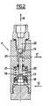
- the device is completed by the air-controlled relief valve and designated as a whole by 11 in FIG. 1.
- the pilot air arrives by the connection 12 coming from the connection 8 located between the two valves 6 and 7, and it acts on a piston 13, which controls by a rod 14 the closing of a valve 15 constituted by a ball blocking the arrival of a hydraulic connection 16 connected to the lubrication line 3 downstream of the pump 1.
- this valve 15 authorizes the discharge of the lubricant through 17 which ensures the return to the reserve.
- a long cycle timer periodically triggers the lubrication cycles, for example every hour.
- the duration of the lubrication cycle can be fixed, either by an intermediate value time delay, for example one or more tens of seconds, or even by a lubrication line end switch when using metering distributors with successive operations.
- a short cycle delay for example of one or more seconds, alternately produces excitation and quotation of the solenoid valve 7 during the entire lubrication cycle, that is to say during the entire period of time during which the solenoid valve 6 is itself energized.
- the long cycle timer When the long cycle timer triggers a lubrication cycle, it produces the supply of the solenoid valve 6 throughout the duration of this cycle, so that the pipes 8 and 12 are supplied with compressed air, thereby closing the valve 15 and supplying valve 7, which is alternately energized and then de-energized by the short cycle time delay several times during the lubrication cycle, thus producing several round trips of the pressure multiplier piston of pump 1, the flow rate sent into the line lubrication 3 is therefore a function of this number of strokes and can be determined at will.
- everything returns to the rest state indicated above, a state in which the relief valve 15 produced by 16 and 17 discharges the lubricant pressure in the lubrication line 3.
- timer is electronic, with binary counting over several decades from a time base, as is most often the case, long cycle and short cycle, or even intermediate, time delays place, can consist of simple outings taken from appropriate decades.
- the invention allows the use of a pump of smaller dimensions and of a simpler type, with two simple valves d 'suction and discharge without further complications, which compensates from the cost point of view the addition of the additional solenoid valve and the piloted valve as well as the electronic modification.
Landscapes
- Engineering & Computer Science (AREA)
- General Engineering & Computer Science (AREA)
- Mechanical Engineering (AREA)
- Compressors, Vaccum Pumps And Other Relevant Systems (AREA)
- Reciprocating Pumps (AREA)
- Details Of Reciprocating Pumps (AREA)
- General Details Of Gearings (AREA)
Claims (2)
dadurch gekennzeichnet, dass sie zwei der als Einhubpumpe ausgebildeten Schmiermittelpumpe (1) zugeordnete Zweiwege-Elektroventile (6, 7) mit jeweils drei Anschlüssen aufweist, die mit ihren Hochdruckwegen hintereinanderliegend zwischen der Druckluftquelle (5) und der Pumpe (1) in einer die Druckluftzufuhrleitung (4) der Pumpe steuernden Weise angeordnet sind, wobei jedes Elektroventil zwei Stellungen aufweist, von denen in einer die Zufuhrleitung (4) mit der Druckluftquelle (5) und in der anderen die Zufuhrleitung (4) mit der Entlüftung (der Atmosphär) verbunden ist, dass der Steuerluftdruck für das Entlastungsventil (11) zwischen den beiden Elektriventilen (6, 7) abgenommen (8) ist und dass die Zeitsteuerung derart ausgebildet ist, dass periodisch jeweils in einem langen Zyklus die dauernde Öffnung des am weitesten stromaufwärts liegenden Ventiles (6) während der ganzen Zeit des Schmierzyklus und während dieser Zeit mit einem jeweils kurzen Zyklus abwechselnd das mehrere Male aufeinanderfolgende Öffnen und Schliessen des am weitesten stromabwärts liegenden Elektroventiles (7) bewirkt werden, wobei die beiden Elektroventile (6, 7) am Ende jedes Zyklus in der Entlüftungsstellung gelassen werden.
Applications Claiming Priority (2)
| Application Number | Priority Date | Filing Date | Title |
|---|---|---|---|
| FR8704175 | 1987-03-25 | ||
| FR8704175A FR2613033B1 (fr) | 1987-03-25 | 1987-03-25 | Alimentation pour graissage centralise |
Publications (2)
| Publication Number | Publication Date |
|---|---|
| EP0284866A1 EP0284866A1 (de) | 1988-10-05 |
| EP0284866B1 true EP0284866B1 (de) | 1990-11-14 |
Family
ID=9349428
Family Applications (1)
| Application Number | Title | Priority Date | Filing Date |
|---|---|---|---|
| EP88104003A Expired - Lifetime EP0284866B1 (de) | 1987-03-25 | 1988-03-14 | Zufuhr für Zentralschmiersystem |
Country Status (3)
| Country | Link |
|---|---|
| EP (1) | EP0284866B1 (de) |
| DE (1) | DE3861038D1 (de) |
| FR (1) | FR2613033B1 (de) |
Families Citing this family (2)
| Publication number | Priority date | Publication date | Assignee | Title |
|---|---|---|---|---|
| ATE91008T1 (de) * | 1989-09-28 | 1993-07-15 | Hydac Technology Gmbh | Schmiermittelfoerdereinrichtung. |
| US5042618A (en) * | 1990-08-09 | 1991-08-27 | Trico Mfg. Corp. | Liquid/gas delivery system |
Citations (1)
| Publication number | Priority date | Publication date | Assignee | Title |
|---|---|---|---|---|
| EP0247398A1 (de) * | 1986-05-29 | 1987-12-02 | Consortium De Recherches Pour L'application Des Fluides, Craf | Elektronische Steuerung für eine Zentralschmiereinrichtung, insbesondere für Kraftwagen |
Family Cites Families (7)
| Publication number | Priority date | Publication date | Assignee | Title |
|---|---|---|---|---|
| FR8944E (fr) * | 1907-09-23 | 1908-07-24 | Gustave Frederic Dorian | Distributeur-compte-gouttes à liquide unique refoulé à basse ou haute pression |
| US1970591A (en) * | 1931-05-07 | 1934-08-21 | Lincoln Eng Co | Lubricating apparatus |
| US2206335A (en) * | 1938-02-23 | 1940-07-02 | Lincoln Eng Co | Lubricating apparatus |
| US2328812A (en) * | 1942-03-16 | 1943-09-07 | Lincoln Eng Co | Venting apparatus |
| US2498407A (en) * | 1943-10-30 | 1950-02-21 | Charles A Fine | Means of metering and delivering lubricants and the like |
| US3985205A (en) * | 1975-01-08 | 1976-10-12 | Ab Assa | Lubricating system |
| US4674030A (en) * | 1984-01-24 | 1987-06-16 | Bijur Lubricating Corp. | Lubricating system control circuit |
-
1987
- 1987-03-25 FR FR8704175A patent/FR2613033B1/fr not_active Expired
-
1988
- 1988-03-14 DE DE8888104003T patent/DE3861038D1/de not_active Expired - Fee Related
- 1988-03-14 EP EP88104003A patent/EP0284866B1/de not_active Expired - Lifetime
Patent Citations (1)
| Publication number | Priority date | Publication date | Assignee | Title |
|---|---|---|---|---|
| EP0247398A1 (de) * | 1986-05-29 | 1987-12-02 | Consortium De Recherches Pour L'application Des Fluides, Craf | Elektronische Steuerung für eine Zentralschmiereinrichtung, insbesondere für Kraftwagen |
Also Published As
| Publication number | Publication date |
|---|---|
| FR2613033A1 (fr) | 1988-09-30 |
| EP0284866A1 (de) | 1988-10-05 |
| FR2613033B1 (fr) | 1989-06-23 |
| DE3861038D1 (de) | 1990-12-20 |
Similar Documents
| Publication | Publication Date | Title |
|---|---|---|
| EP0077230B1 (de) | Einrichtung zur Gasströmungsmodulation im Abgasschalldämpfer von Brennkraftmaschinen | |
| FR2604219A1 (fr) | Procede et dispositif d'injection de carburant pour moteurs a combustion interne. | |
| EP2006587B1 (de) | Dichtungsventilsystem | |
| EP0284866B1 (de) | Zufuhr für Zentralschmiersystem | |
| FR2635573A1 (fr) | Vanne de commande pour chasse d'eau | |
| FR2656061A1 (fr) | Vanne a tiroir et quatre voies. | |
| CA1162130A (fr) | Convertisseur de couple hydrodynamique muni de moyens de pontage | |
| FR2466650A1 (fr) | Dispositif de commande actionne par pression | |
| FR2759736A1 (fr) | Unite de commande d'un systeme d'injection pour un moteur a combustion interne a plusieurs cylindres | |
| FR2514848A1 (fr) | Circuit hydraulique de commande pour boite de vitesses automatique de vehicule a moteur a combustion interne | |
| FR2461114A1 (fr) | Pompe a injection d'alimentation de moteur a combustion interne | |
| FR2551139A1 (fr) | Demarreur a commande par air comprime, notamment pour moteurs a combustion interne | |
| FR2509829A1 (fr) | Regulateur de pression a commande par solenoide | |
| WO1987007352A1 (fr) | Vanne de distribution de liquide | |
| FR2638982A1 (de) | ||
| FR2711433A1 (fr) | Régulateur coaxial de débit. | |
| FR2787831A1 (fr) | Installation d'injection de carburant | |
| EP0006770B1 (de) | Elektromagnetisches Ventil, insbesondere für einen Vergaser | |
| EP0564363B1 (de) | Universelle Steuereinrichtung für den Verbraucher eines automatischen Getriebes | |
| EP0368691A1 (de) | Steuervorrichtung eines Kraftverstärkers, insbesondere für Kraftfahrzeugbremsanlagen | |
| FR2534631A1 (fr) | Injecteur de carburant | |
| FR2552322A1 (fr) | Ensemble a valves pour dispositif de lavage des parties intimes du corps humain | |
| FR2729184A1 (fr) | Dispositif a soupape, notamment pour une soupape de reinjection de gaz d'echappement d'un moteur a combustion interne | |
| FR2563312A1 (fr) | Soupape de reduction de pression | |
| FR2482670A1 (fr) | Injecteur de combustible |
Legal Events
| Date | Code | Title | Description |
|---|---|---|---|
| PUAI | Public reference made under article 153(3) epc to a published international application that has entered the european phase |
Free format text: ORIGINAL CODE: 0009012 |
|
| AK | Designated contracting states |
Kind code of ref document: A1 Designated state(s): BE CH DE ES FR GB IT LI LU NL SE |
|
| 17P | Request for examination filed |
Effective date: 19890222 |
|
| 17Q | First examination report despatched |
Effective date: 19890825 |
|
| GRAA | (expected) grant |
Free format text: ORIGINAL CODE: 0009210 |
|
| AK | Designated contracting states |
Kind code of ref document: B1 Designated state(s): BE CH DE ES FR GB IT LI LU NL SE |
|
| PG25 | Lapsed in a contracting state [announced via postgrant information from national office to epo] |
Ref country code: IT Free format text: LAPSE BECAUSE OF FAILURE TO SUBMIT A TRANSLATION OF THE DESCRIPTION OR TO PAY THE FEE WITHIN THE PRE;WARNING: LAPSES OF ITALIAN PATENTS WITH EFFECTIVE DATE BEFORE 2007 MAY HAVE OCCURRED AT ANY TIME BEFORE 2007. THE CORRECT EFFECTIVE DATE MAY BE DIFFERENT FROM THE ONE RECORDED.SCRIBED TIME-LIMIT Effective date: 19901114 Ref country code: ES Free format text: THE PATENT HAS BEEN ANNULLED BY A DECISION OF A NATIONAL AUTHORITY Effective date: 19901114 |
|
| GBT | Gb: translation of ep patent filed (gb section 77(6)(a)/1977) | ||
| REF | Corresponds to: |
Ref document number: 3861038 Country of ref document: DE Date of ref document: 19901220 |
|
| PLBE | No opposition filed within time limit |
Free format text: ORIGINAL CODE: 0009261 |
|
| STAA | Information on the status of an ep patent application or granted ep patent |
Free format text: STATUS: NO OPPOSITION FILED WITHIN TIME LIMIT |
|
| 26N | No opposition filed | ||
| PGFP | Annual fee paid to national office [announced via postgrant information from national office to epo] |
Ref country code: GB Payment date: 19920306 Year of fee payment: 5 |
|
| PGFP | Annual fee paid to national office [announced via postgrant information from national office to epo] |
Ref country code: SE Payment date: 19920311 Year of fee payment: 5 |
|
| PGFP | Annual fee paid to national office [announced via postgrant information from national office to epo] |
Ref country code: LU Payment date: 19920312 Year of fee payment: 5 |
|
| PGFP | Annual fee paid to national office [announced via postgrant information from national office to epo] |
Ref country code: CH Payment date: 19920319 Year of fee payment: 5 |
|
| PGFP | Annual fee paid to national office [announced via postgrant information from national office to epo] |
Ref country code: NL Payment date: 19920331 Year of fee payment: 5 |
|
| EPTA | Lu: last paid annual fee | ||
| PG25 | Lapsed in a contracting state [announced via postgrant information from national office to epo] |
Ref country code: LU Free format text: LAPSE BECAUSE OF NON-PAYMENT OF DUE FEES Effective date: 19930314 Ref country code: GB Effective date: 19930314 |
|
| PG25 | Lapsed in a contracting state [announced via postgrant information from national office to epo] |
Ref country code: SE Effective date: 19930315 |
|
| PG25 | Lapsed in a contracting state [announced via postgrant information from national office to epo] |
Ref country code: LI Effective date: 19930331 Ref country code: CH Effective date: 19930331 |
|
| PGFP | Annual fee paid to national office [announced via postgrant information from national office to epo] |
Ref country code: BE Payment date: 19930406 Year of fee payment: 6 |
|
| PG25 | Lapsed in a contracting state [announced via postgrant information from national office to epo] |
Ref country code: NL Effective date: 19931001 |
|
| GBPC | Gb: european patent ceased through non-payment of renewal fee |
Effective date: 19930314 |
|
| NLV4 | Nl: lapsed or anulled due to non-payment of the annual fee | ||
| REG | Reference to a national code |
Ref country code: CH Ref legal event code: PL |
|
| PG25 | Lapsed in a contracting state [announced via postgrant information from national office to epo] |
Ref country code: BE Effective date: 19940331 |
|
| BERE | Be: lapsed |
Owner name: CONSORTIUM DE RECHERCHES POUR L'APPLICATION DES FL Effective date: 19940331 |
|
| EUG | Se: european patent has lapsed |
Ref document number: 88104003.4 Effective date: 19931008 |
|
| PGFP | Annual fee paid to national office [announced via postgrant information from national office to epo] |
Ref country code: DE Payment date: 19960318 Year of fee payment: 9 |
|
| PG25 | Lapsed in a contracting state [announced via postgrant information from national office to epo] |
Ref country code: DE Effective date: 19971202 |
|
| PGFP | Annual fee paid to national office [announced via postgrant information from national office to epo] |
Ref country code: FR Payment date: 19980310 Year of fee payment: 11 |
|
| PG25 | Lapsed in a contracting state [announced via postgrant information from national office to epo] |
Ref country code: FR Free format text: LAPSE BECAUSE OF NON-PAYMENT OF DUE FEES Effective date: 19991130 |
|
| REG | Reference to a national code |
Ref country code: FR Ref legal event code: ST |