EP0284535B1 - Fahrrad, dessen Räder nur an einer Seite des Rahmens befestigt sind - Google Patents
Fahrrad, dessen Räder nur an einer Seite des Rahmens befestigt sind Download PDFInfo
- Publication number
- EP0284535B1 EP0284535B1 EP88470003A EP88470003A EP0284535B1 EP 0284535 B1 EP0284535 B1 EP 0284535B1 EP 88470003 A EP88470003 A EP 88470003A EP 88470003 A EP88470003 A EP 88470003A EP 0284535 B1 EP0284535 B1 EP 0284535B1
- Authority
- EP
- European Patent Office
- Prior art keywords
- wheel
- frame
- brake
- fixed
- bicycle
- Prior art date
- Legal status (The legal status is an assumption and is not a legal conclusion. Google has not performed a legal analysis and makes no representation as to the accuracy of the status listed.)
- Expired - Lifetime
Links
- 238000004873 anchoring Methods 0.000 claims description 5
- 238000003466 welding Methods 0.000 claims description 3
- 238000005476 soldering Methods 0.000 claims 1
- 241001417494 Sciaenidae Species 0.000 description 4
- 238000005516 engineering process Methods 0.000 description 3
- 238000005219 brazing Methods 0.000 description 2
- 238000002788 crimping Methods 0.000 description 2
- 230000006978 adaptation Effects 0.000 description 1
- 230000005540 biological transmission Effects 0.000 description 1
- 238000012423 maintenance Methods 0.000 description 1
- 230000007257 malfunction Effects 0.000 description 1
- 238000004519 manufacturing process Methods 0.000 description 1
- 238000000034 method Methods 0.000 description 1
- 230000010355 oscillation Effects 0.000 description 1
Images


Classifications
-
- B—PERFORMING OPERATIONS; TRANSPORTING
- B62—LAND VEHICLES FOR TRAVELLING OTHERWISE THAN ON RAILS
- B62K—CYCLES; CYCLE FRAMES; CYCLE STEERING DEVICES; RIDER-OPERATED TERMINAL CONTROLS SPECIALLY ADAPTED FOR CYCLES; CYCLE AXLE SUSPENSIONS; CYCLE SIDE-CARS, FORECARS, OR THE LIKE
- B62K21/00—Steering devices
- B62K21/02—Front wheel forks or equivalent, e.g. single tine
-
- B—PERFORMING OPERATIONS; TRANSPORTING
- B62—LAND VEHICLES FOR TRAVELLING OTHERWISE THAN ON RAILS
- B62K—CYCLES; CYCLE FRAMES; CYCLE STEERING DEVICES; RIDER-OPERATED TERMINAL CONTROLS SPECIALLY ADAPTED FOR CYCLES; CYCLE AXLE SUSPENSIONS; CYCLE SIDE-CARS, FORECARS, OR THE LIKE
- B62K25/00—Axle suspensions
- B62K25/005—Axle suspensions characterised by the axle being supported at one end only
-
- B—PERFORMING OPERATIONS; TRANSPORTING
- B62—LAND VEHICLES FOR TRAVELLING OTHERWISE THAN ON RAILS
- B62K—CYCLES; CYCLE FRAMES; CYCLE STEERING DEVICES; RIDER-OPERATED TERMINAL CONTROLS SPECIALLY ADAPTED FOR CYCLES; CYCLE AXLE SUSPENSIONS; CYCLE SIDE-CARS, FORECARS, OR THE LIKE
- B62K25/00—Axle suspensions
- B62K25/02—Axle suspensions for mounting axles rigidly on cycle frame or fork, e.g. adjustably
-
- B—PERFORMING OPERATIONS; TRANSPORTING
- B62—LAND VEHICLES FOR TRAVELLING OTHERWISE THAN ON RAILS
- B62K—CYCLES; CYCLE FRAMES; CYCLE STEERING DEVICES; RIDER-OPERATED TERMINAL CONTROLS SPECIALLY ADAPTED FOR CYCLES; CYCLE AXLE SUSPENSIONS; CYCLE SIDE-CARS, FORECARS, OR THE LIKE
- B62K3/00—Bicycles
- B62K3/02—Frames
Definitions
- the present invention relates to a bicycle in which at least the rear wheel is cantilevered on the elements which constitute the frame of the bicycle, the rear part of the frame being formed by an arm which links the rear wheel to the frame, the arm being fixed on the bottom bracket of the frame by welding or brazing, its shape being such that it allows the passage of the rear wheel and the chain, said arm receiving at its end a welded or brazed socket in which is housed a bearing, said bicycle comprising a corresponding rear brake.
- the fixing of the wheels on the frame of a bicycle is traditionally carried out by means of a front fork which oscillates on the frame and a rear fork which forms an integral part of the frame.
- a bicycle wheel rotates around an axis and this axis is fixed by its two ends to the front fork arms for the front wheel and to the seat stays and frame bases which constitute the rear fork.
- a bicycle frame is therefore symmetrical with regard to the fixing of wheels.
- document EP-A-0 187 170 describes a bicycle whose rear wheel is cantilevered, but in which the rear wheel turns on two bearings, the drive being operated by keys.
- the chain is placed in a casing, which is impractical for the maintenance of so-called "all terrain” bicycles.
- this bicycle is too complex in design and does not include the possibility of simple adaptation of a gear change.
- the device according to the invention overcomes disadvantages of the prior art.
- the rear brake support consists of two fixing lugs fixed by one end to the seat tube of the frame, at the other end being fixed two lateral sockets traversed by a screw, at the end of this screw being a shoulder on which a nut comes to rest, said screw ensuring the connection between the side sockets and a central socket, the connection being such that it ensures a rotation of angle ⁇ around the axis xx ′ of the central sleeve and of the screw relative to the frame, the rear brake on the rim coming to be fixed on this mechanism by means of an axis which passes through both rooms.
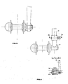
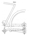
- the device comprises a single arm which links the rear wheel to the frame according to FIG. 1.
- This arm 1 is fixed to the bottom bracket of the frame by welding or brazing. Its shape is such that it allows the passage of the rear wheel and the chain.
- This arm receives at its end a socket 2 welded or brazed in which is housed a bearing 3.
- This bearing is stopped in translation in its housing by a shoulder and by bonding or then by a shoulder and crimping or by a shoulder and an elastic ring or rod.
- This bearing is crossed by an axis 4 which receives a free wheel at its end.
- On the left side of this axis is fixed the means 5 which supports the wheel which can be of all types known up to now. The whole is fixed together by a nut 6 to one or more threads whose pitch direction is such that the tensile force automatically ensures the tightening of the nut.
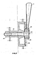
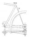
- the freewheel may comprise several pinions according to FIG. 2.
- the bicycle is then equipped with a gear change mechanism fixed at 7.
- the chain can be wrapped by a waterproof or non-waterproof casing which remains in position when the rear wheel is removed.
- one solution is to oscillate a conventional rim brake around an axis.
- the amplitude of the oscillation must be sufficient to allow easy removal of the rear wheel.
- the rear wheel On a bicycle equipped with this device, the rear wheel is extracted first by rocking the brake, then it is sufficient to remove the fixing nut from the rear wheel. So he is easy to remove the rear wheel because the chain, the gear change mechanism if it exists and the chain case if it exists remain in place on the bicycle.
- refitting the rear wheel on the bicycle simply place it on its axle, screw the fixing nut until it is in contact with the rear wheel hub and tilt the rear brake to return it to the operating position.
- a variant of the brake system on the rear wheel consists in using a drum brake in the rear hub according to FIG. 4.
- the flange 9 is stopped in rotation by an anchoring lug linked to the arm which supports the wheels.
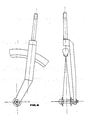
- the device according to the invention comprises a steering system the connection of which between the front wheel and the frame is effected by means of a support arm connected to the steering pivot tube which oscillates inside the frame socket in accordance with known solutions used in bicycle technology.
- FIG. 6 represents a possible solution. If the axis of the front wheel is fixed by thread or by interlocking at the base of the steering support arm, then this axis is fixed in rotation relative to the frame. The front wheel and its hub then rotate around this axis via annular bearings or a system of balls, cones and cups which are known types of bearings and used in bicycle technology.
- the removal of the front wheel is done according to the solutions proposed either by unscrewing the front wheel axle relative to the support arm, or by acting on the conical pin in Figure 6 and pulling the front wheel down.
- the front wheel is refitted without major difficulties in the opposite direction to the removal operations.
- the device comprises, according to FIG. 7, socket 10 welded or brazed to the support arm 11 in which a bearing 12 is housed.
- This bearing is stopped in translation in its housing by a shoulder and by bonding or else by a shoulder and crimping or else by a shoulder and an elastic ring or rod.
- This bearing is crossed by an axis 13 shouldered at its end, on this axis is fixed the hub 14 in which the brake drum is located.
- a flange 15 which supports the brake linings and the brake control mechanism is fitted inside the drum and is centered on the sleeve.
- the flange 15 is stopped in rotation by an anchoring lug linked to the arm which supports the wheel.
- the whole is assembled by a nut 16 with one or more threads. When removing, simply unscrew the nut to remove the front wheel instantly.
- the brake flange, the brake control mechanism and the anchoring of the brake on the front wheel support remain in position and are not manipulated either when removing or installing the wheel. before.
- the front wheel is installed in the reverse direction to the removal operation. Note that the nut must be permanently tightened when reassembling the front wheel on the frame.
- the steering device according to the invention can be located either to the right or to the left of the front wheel, the important thing being to ensure good alignment of the front wheel and the axis of longitudinal symmetry from the bicycle.
- the fixing nut is mounted on the wheel hub so that it always performs its tightening function and that in addition it is always linked to its hub in the event of removal of the wheel, so as to obtain a "captive" nut.
- a variant of the device according to the invention makes it possible to use, when the brakes are with drums in the hub, identical wheels for the front and for the rear of the bicycle, therefore to manufacture a single type of wheel for a bicycle.
- the device according to the invention can be applied to all types and all sizes of bicycles, whether they are intended for adults, children, competition, hiking, etc.
- a bicycle equipped with the device according to the invention can also receive all types of accessories known and used in bicycle technology.
- FIG. 5 represents an example of attachment of the front wheel to the steering system according to the device according to the invention.
- the tightening of the axle of the front wheel on the steering system can be obtained according to FIG. 5 for example by using a screwdriver which is introduced into the slot at the end of the axle of the front wheel.
- the tightening of the axis of the front wheel on the steering system can be obtained by other means than the screwdriver without departing from the spirit of the invention. It suffices to modify the end of the axle of the front wheel according to the chosen clamping means.
- Figure 6 shows another example of fixing the front wheel to the steering system according to the device according to the invention.
- the part 17 which can be welded to the wheel axle or be an integral part of the wheel axle when its end is bent at about 90 ° comes to fit inside the steering tube 18 via of the part 19.
- the part 17 has at its end a flat on which the conical pin 20 is supported.
- This pin 20 passes through the part 19 right through, it has a thread at one end and the operating member at the other pivoting 21. To remove the wheel, it suffices for example to slightly unscrew the pin 20 using the operating member 21 and to pull the whole of the wheel down. The wheel refitting operation is carried out in the opposite direction to the removal operation.
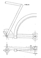
- FIG. 12 represents a variant of the rear part of a bicycle equipped according to the invention with a drum brake in the hub or not, with a chain case or not, with a mechanism for changing the speeds or not, ...
- a tube 22 which stiffens the rear part of the frame and limits deformation of the wheel support arm.
- the support consists of two fixing lugs 23 fixed at one end to the seat tube of the frame, at the other end are fixed two sockets 24. These sockets 24 are traversed for example by a screw 25 to the at the end of this screw is a shoulder on which nut 26 rests. This screw provides the connection between the lateral sockets and the central socket 27.
- connection between the socket 27 and the sockets 24 is such that it ensures a rotation of angle ⁇ and of axis x′x of the socket 27 and of the screw 25 relative to the frame.
- the rear rim brake is fixed on this mechanism thanks to the pin 28 which crosses both parts 27 and 25.
- FIG. 15 represents according to the invention an example of "captive" nut for fixing bicycle wheels in accordance with FIGS. 1, 2, 3, 4, 7, 9B, 11, 12, 13.
- a nut 29 provided a shoulder 30 fixes the wheel on the bicycle. This nut is constantly linked to the wheel hub, even in the event of removal via the flange 31.
Landscapes
- Engineering & Computer Science (AREA)
- Mechanical Engineering (AREA)
- Braking Arrangements (AREA)
- Motorcycle And Bicycle Frame (AREA)
- Axle Suspensions And Sidecars For Cycles (AREA)
Claims (4)
Applications Claiming Priority (2)
| Application Number | Priority Date | Filing Date | Title |
|---|---|---|---|
| FR8702456 | 1987-02-23 | ||
| FR8702456A FR2611641B1 (fr) | 1987-02-23 | 1987-02-23 | Bicyclette dont les roues sont fixees en porte a faux sur le cadre |
Publications (2)
| Publication Number | Publication Date |
|---|---|
| EP0284535A1 EP0284535A1 (de) | 1988-09-28 |
| EP0284535B1 true EP0284535B1 (de) | 1992-04-29 |
Family
ID=9348274
Family Applications (1)
| Application Number | Title | Priority Date | Filing Date |
|---|---|---|---|
| EP88470003A Expired - Lifetime EP0284535B1 (de) | 1987-02-23 | 1988-02-23 | Fahrrad, dessen Räder nur an einer Seite des Rahmens befestigt sind |
Country Status (4)
| Country | Link |
|---|---|
| EP (1) | EP0284535B1 (de) |
| DE (1) | DE3870500D1 (de) |
| ES (1) | ES2032999T3 (de) |
| FR (1) | FR2611641B1 (de) |
Cited By (1)
| Publication number | Priority date | Publication date | Assignee | Title |
|---|---|---|---|---|
| US8491427B2 (en) | 2007-05-05 | 2013-07-23 | Jochen Klieber | Derailleur hanger with insertion aid |
Families Citing this family (7)
| Publication number | Priority date | Publication date | Assignee | Title |
|---|---|---|---|---|
| ES2067389B1 (es) * | 1993-02-23 | 1998-03-01 | Navas Antonio Guerra | Buje para ruedas de bicicletas. |
| ES2153642T3 (es) * | 1996-12-02 | 2001-03-01 | Hold X | Triciclo transformable en bicicleta. |
| FR2855456B1 (fr) | 2003-05-28 | 2006-11-03 | Mavic Sa | Velo prevu pour la pratique du cyclisme et roue a utiliser sur un tel velo |
| US7793960B2 (en) * | 2008-04-01 | 2010-09-14 | Aleksandr Sherman | Bicycle wheel mounting assembly |
| RU2460663C1 (ru) * | 2011-02-08 | 2012-09-10 | Юрий Антонович Петровский | Гоночный велосипед |
| DE102011053875B3 (de) * | 2011-09-23 | 2013-02-21 | Karsten Bettin | Rahmen, wahlweise für Fahrräder oder für Anhängefahrräder |
| ITPD20120388A1 (it) * | 2012-12-19 | 2014-06-20 | Diego Pizzato | Metodo di bilanciamento di una bicicletta e zavorra bilanciatrice per una bicicletta |
Family Cites Families (3)
| Publication number | Priority date | Publication date | Assignee | Title |
|---|---|---|---|---|
| US4170369A (en) * | 1978-01-23 | 1979-10-09 | Lauren Strutman | Bicycle wheel suspension, driving and braking assembly |
| FR2473978B1 (fr) * | 1980-01-23 | 1985-06-14 | Jacquin Claude | Trottinette tous terrains permettant l'utilisation l'utilisation des teleskis, telesieges et telecabines |
| US4526249A (en) * | 1983-05-25 | 1985-07-02 | Parker James G | Front suspension system for a motorcycle |
-
1987
- 1987-02-23 FR FR8702456A patent/FR2611641B1/fr not_active Expired - Lifetime
-
1988
- 1988-02-23 DE DE8888470003T patent/DE3870500D1/de not_active Expired - Fee Related
- 1988-02-23 EP EP88470003A patent/EP0284535B1/de not_active Expired - Lifetime
- 1988-02-23 ES ES198888470003T patent/ES2032999T3/es not_active Expired - Lifetime
Cited By (1)
| Publication number | Priority date | Publication date | Assignee | Title |
|---|---|---|---|---|
| US8491427B2 (en) | 2007-05-05 | 2013-07-23 | Jochen Klieber | Derailleur hanger with insertion aid |
Also Published As
| Publication number | Publication date |
|---|---|
| FR2611641B1 (fr) | 1990-04-13 |
| DE3870500D1 (de) | 1992-06-04 |
| EP0284535A1 (de) | 1988-09-28 |
| ES2032999T3 (es) | 1993-03-01 |
| FR2611641A1 (fr) | 1988-09-09 |
Similar Documents
| Publication | Publication Date | Title |
|---|---|---|
| EP0284535B1 (de) | Fahrrad, dessen Räder nur an einer Seite des Rahmens befestigt sind | |
| FR2736033A1 (fr) | Dispositif d'entrainement a roue libre, notamment pour une bicyclette | |
| EP3187402A1 (de) | Sattelträger einer scheibenbremse für ein fahrrad oder ähnlich | |
| FR2501124A1 (fr) | Moyeu de roue de cycle | |
| FR2533283A1 (fr) | Moyeu a roue libre pour bicyclette | |
| EP0191710B1 (de) | Fahrrad | |
| FR2602185A1 (fr) | Dispositif de support oscillant pour la roue motrice d'un vehicule | |
| FR2597557A1 (fr) | Roulement de roue integre pour roue motrice arriere | |
| FR2503051A1 (fr) | Moyeu pour vehicule a deux roues | |
| WO2005085006A1 (fr) | Porte-charge destine a equiper l'arriere d'un vehicule automobile | |
| EP1801004B1 (de) | Klapprad | |
| FR2547264A1 (fr) | Dispositif de retenue d'une des roues d'un vehicule a deux roues | |
| EP0983186B1 (de) | Fahrradpedal mit kraftübersetzungsgetriebe | |
| FR2771070A3 (fr) | Dispositif a excentrique pour jeu de pignons de bicyclette | |
| FR2484353A1 (fr) | Dispositif d'accouplement entre la partie moteur et la partie cycle d'un cyclomoteur | |
| FR2614657A1 (fr) | Dispositif pour bloquer des composants d'une bicyclette | |
| FR2733198A1 (fr) | Structure de suspension de roue avant d'un vehicule motorise a deux roues | |
| FR2650549A1 (fr) | Dispositif de fixation d'un cadre de bicyclette | |
| WO2008113906A1 (fr) | Moyens pour retirer rapidement les roues ou au moins les pneus d'un deux roue monotrace | |
| FR2758519A3 (fr) | Mecanisme de frein pour bicyclettes | |
| FR3145510A1 (fr) | Perfectionnement d’un changement rapide des roues sur une bicyclette | |
| FR2550752A1 (fr) | Pedalier a developpement variable | |
| FR2506412A1 (fr) | Moyeu a roue libre pour bicyclettes et vehicules similaires | |
| BE855828A (fr) | Frein de bicyclette actionne par les petales | |
| FR3161892A1 (fr) | Moyeu de roue sur une bicyclette |
Legal Events
| Date | Code | Title | Description |
|---|---|---|---|
| PUAI | Public reference made under article 153(3) epc to a published international application that has entered the european phase |
Free format text: ORIGINAL CODE: 0009012 |
|
| AK | Designated contracting states |
Kind code of ref document: A1 Designated state(s): BE DE ES FR GB IT LU NL |
|
| 17P | Request for examination filed |
Effective date: 19890103 |
|
| 17Q | First examination report despatched |
Effective date: 19900302 |
|
| GRAA | (expected) grant |
Free format text: ORIGINAL CODE: 0009210 |
|
| AK | Designated contracting states |
Kind code of ref document: B1 Designated state(s): BE DE ES FR GB IT LU NL |
|
| REF | Corresponds to: |
Ref document number: 3870500 Country of ref document: DE Date of ref document: 19920604 |
|
| ITF | It: translation for a ep patent filed | ||
| GBT | Gb: translation of ep patent filed (gb section 77(6)(a)/1977) | ||
| PGFP | Annual fee paid to national office [announced via postgrant information from national office to epo] |
Ref country code: GB Payment date: 19930223 Year of fee payment: 6 |
|
| PGFP | Annual fee paid to national office [announced via postgrant information from national office to epo] |
Ref country code: LU Payment date: 19930224 Year of fee payment: 6 |
|
| PGFP | Annual fee paid to national office [announced via postgrant information from national office to epo] |
Ref country code: ES Payment date: 19930226 Year of fee payment: 6 |
|
| PGFP | Annual fee paid to national office [announced via postgrant information from national office to epo] |
Ref country code: NL Payment date: 19930228 Year of fee payment: 6 |
|
| REG | Reference to a national code |
Ref country code: ES Ref legal event code: FG2A Ref document number: 2032999 Country of ref document: ES Kind code of ref document: T3 |
|
| PLBE | No opposition filed within time limit |
Free format text: ORIGINAL CODE: 0009261 |
|
| STAA | Information on the status of an ep patent application or granted ep patent |
Free format text: STATUS: NO OPPOSITION FILED WITHIN TIME LIMIT |
|
| PGFP | Annual fee paid to national office [announced via postgrant information from national office to epo] |
Ref country code: BE Payment date: 19930311 Year of fee payment: 6 |
|
| PGFP | Annual fee paid to national office [announced via postgrant information from national office to epo] |
Ref country code: DE Payment date: 19930324 Year of fee payment: 6 |
|
| 26N | No opposition filed | ||
| PGFP | Annual fee paid to national office [announced via postgrant information from national office to epo] |
Ref country code: FR Payment date: 19930511 Year of fee payment: 6 |
|
| EPTA | Lu: last paid annual fee | ||
| PG25 | Lapsed in a contracting state [announced via postgrant information from national office to epo] |
Ref country code: LU Free format text: LAPSE BECAUSE OF NON-PAYMENT OF DUE FEES Effective date: 19940223 Ref country code: GB Effective date: 19940223 |
|
| PG25 | Lapsed in a contracting state [announced via postgrant information from national office to epo] |
Ref country code: ES Free format text: LAPSE BECAUSE OF NON-PAYMENT OF DUE FEES Effective date: 19940224 |
|
| PG25 | Lapsed in a contracting state [announced via postgrant information from national office to epo] |
Ref country code: BE Effective date: 19940228 |
|
| BERE | Be: lapsed |
Owner name: GUILLOT JEAN MARIE Effective date: 19940228 Owner name: LAITI MICHEL Effective date: 19940228 |
|
| PG25 | Lapsed in a contracting state [announced via postgrant information from national office to epo] |
Ref country code: NL Effective date: 19940901 |
|
| NLV4 | Nl: lapsed or anulled due to non-payment of the annual fee | ||
| GBPC | Gb: european patent ceased through non-payment of renewal fee |
Effective date: 19940223 |
|
| PG25 | Lapsed in a contracting state [announced via postgrant information from national office to epo] |
Ref country code: FR Effective date: 19941031 |
|
| PG25 | Lapsed in a contracting state [announced via postgrant information from national office to epo] |
Ref country code: DE Effective date: 19941101 |
|
| REG | Reference to a national code |
Ref country code: FR Ref legal event code: ST |
|
| REG | Reference to a national code |
Ref country code: ES Ref legal event code: FD2A Effective date: 19990503 |
|
| PG25 | Lapsed in a contracting state [announced via postgrant information from national office to epo] |
Ref country code: IT Free format text: LAPSE BECAUSE OF NON-PAYMENT OF DUE FEES;WARNING: LAPSES OF ITALIAN PATENTS WITH EFFECTIVE DATE BEFORE 2007 MAY HAVE OCCURRED AT ANY TIME BEFORE 2007. THE CORRECT EFFECTIVE DATE MAY BE DIFFERENT FROM THE ONE RECORDED. Effective date: 20050223 |