EP0283258B1 - Scheidungsaufbau zum Aufteilen von Komponenten - Google Patents
Scheidungsaufbau zum Aufteilen von Komponenten Download PDFInfo
- Publication number
- EP0283258B1 EP0283258B1 EP88302279A EP88302279A EP0283258B1 EP 0283258 B1 EP0283258 B1 EP 0283258B1 EP 88302279 A EP88302279 A EP 88302279A EP 88302279 A EP88302279 A EP 88302279A EP 0283258 B1 EP0283258 B1 EP 0283258B1
- Authority
- EP
- European Patent Office
- Prior art keywords
- barrier
- panel
- barrier member
- neck
- aperture
- Prior art date
- Legal status (The legal status is an assumption and is not a legal conclusion. Google has not performed a legal analysis and makes no representation as to the accuracy of the status listed.)
- Expired - Lifetime
Links
- 230000004888 barrier function Effects 0.000 title claims description 101
- 238000000638 solvent extraction Methods 0.000 title claims description 3
- 230000037431 insertion Effects 0.000 claims description 4
- 238000003780 insertion Methods 0.000 claims description 4
- 210000000078 claw Anatomy 0.000 claims description 2
- 241000826860 Trapezium Species 0.000 description 2
- 238000005192 partition Methods 0.000 description 2
- 239000000470 constituent Substances 0.000 description 1
- 238000010276 construction Methods 0.000 description 1
- 238000003754 machining Methods 0.000 description 1
Images


Classifications
-
- H—ELECTRICITY
- H02—GENERATION; CONVERSION OR DISTRIBUTION OF ELECTRIC POWER
- H02B—BOARDS, SUBSTATIONS OR SWITCHING ARRANGEMENTS FOR THE SUPPLY OR DISTRIBUTION OF ELECTRIC POWER
- H02B1/00—Frameworks, boards, panels, desks, casings; Details of substations or switching arrangements
- H02B1/015—Boards, panels, desks; Parts thereof or accessories therefor
- H02B1/04—Mounting thereon of switches or of other devices in general, the switch or device having, or being without, casing
- H02B1/044—Mounting through openings
- H02B1/048—Snap mounting
Definitions
- the present invention relates to a barrier assembly which may be used, for example, to partition off adjacent pushbutton switches on display lamps arrayed in a line within an opening in a mounting panel provided in, for example, a ticket machine.
- a ticket machine a plurality of illuminated button switches that indicate the fares to respective destinations are provided on a mounting panel. When one of the pushbutton switches is pressed, the machine issues a ticket which has printed on it an amount of money corresponding to the fare displayed on the pressed switch.
- the pushbutton switches are arrayed on a mounting panel in a longitudinal line, a lateral line, or in both longitudinal and lateral directions.
- the pushbutton switches are mounted within respective openings provided in the mounting panel and this is done in such a manner that the fare indicating surfaces on the switches are exposed.
- the mounting panel must be provided with a number of openings which corresponds to the number of pushbutton switches required.
- barriers (31) 32 are interposed between each pair of adjacent pushbutton switches A in order to partition them off from each other.
- barrier 31 There are two types known of barrier.
- a first type of barrier 31 (shown in Figs. 10A and 10B) is inserted from the front side of the panel between adjacent switches after the switches A have been fitted into the opening in the mounting panel.
- a second type of barrier 32 (shown in Figs. 11A and 11B) is attached to the respective pushbutton switches A to form one unit, and this pushbutton switch assembly is subsequently secured to the mounting panel.
- the barriers 31 With the first type of barrier 31, after the pushbutton switches have been fitted into the mounting opening, the barriers 31 are inserted from the front of the panel. Retaining step parts 33 shown in Fig. 10B engage the side surfaces of the switches, and thus prevent the pushbutton switches from being pulled out from the front of the panel.
- this type of conventional barrier 31 suffers from the disadvantage that when the clearance between the panel and the switches is large, it may be impossible to prevent the switches from being pushed rearwardly into the panel.
- the step parts 33 project to prevent the barriers 31 from being pulled out forward from the panel, the barriers 31 must be broken when the pushbutton switches need to be replaced. As a result, replacement requires much time and labour, since the barriers 31 cannot be re-used, the cost is increased further.
- the present invention seeks to provide a barrier assembly which, although capable of being removed from the panel aperture when desired, resists being pushed into or pulled out of the panel.
- a barrier assembly for partitioning an aperture in a panel to separate adjacent components mounted in an array in the aperture, the assembly comprising a first barrier member for insertion into said aperture from one side of the panel, and a second barrier member for insertion between said adjacent components from the other side of the panel, the first and second members being mutually engageable.
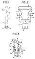
- a barrier assembly comprises an outer barrier member 2 which is inserted from the front of a mounting panel 1 (shown in Fig. 5) and a fixing barrier member 3 which is inserted from the rear of the panel 1.
- the outer barrier member 2 has a head part which is an enlarged front end part.
- the head part 4 abuts and engages the panel surface 6a, thereby preventing the outer barrier member 2 from being pushed further into the opening 5.
- the outer barrier member 2 has a thin-walled main body 6 which is integrally formed with the head part 4; the body 6 is inserted into the opening 5.
- the distal end part 7 of the body 6 is narrower than the body 6 such that the end part 7 has a shape similar to a trapezium and flanges 8a and 8b are provided on both sides, of the distal end part 7.
- the fixing barrier member 3 which engages the outer barrier member has a pin 10 projecting at right angles to the plane of the width of the body 6 from each side surface thereof so as to engage a switch casing 15 (see Figs. 4 and 5) of a pushbutton switch A.
- the fixing barrier member 3 also has two claws formed by arms 11a and 11b extending toward the outer barrier member 2 so that the main body 6 of the outer barrier member 2 fits into the space defined between the arms 11a and 11b.
- the arms 11a and 11b have a larger thickness than that of the main body 6 of the outer barrier member 2.
- the fitting space 12 (shown in Fig. 3) defined between the arms 11a and 11b also has a shape similar to a trapezium.
- Grooves 13a and 13b which guide and accommodate the distal end part 7 of the outer barrier member 2 are provided on the respective inner sides of the arms 11a and 11b.
- the arms 11a and 11b have projections 14a and 14b at their respective distal ends which extend toward each other.
- the projections 14a and 14b engage the corresponding flanges 8a and 8b of the outer barrier member 2; this maintains the fitting engagement against external forces.
- the arms 11a,11b may extend rearwardly, away from the projections 14a,14b to provide wings which, when pushed inwardly, move the projections outwardly thereby to disengage the projections 14a,14b from the flanges 8a,8b.
- the switch casing 15 for accommodating a pushbutton switch A is provided with a pair of leaf springs 20 which maintain the position of the switch casing 15 in the mounting panel 1, as is shown in Fig. 5.
- a rim 16 is provided along the outer periphery of the forward end of the switch casing 15, and abuts the panel surface 6a. When the rim 16 is brought into abutment with the panel 1, the respective distal ends of the leaf springs 20 are brought into resilient contact with the rear surface of the panel 1, thereby securing the switch casing 15, of the pushbutton switch A, to the mounting panel 1.
- the leaf springs 20 are integrally formed with a U-shaped frame 17 and are mounted on the switch casing 15 by fitting the frame 17 into a recess 18 in the outer surface of the casing 15.
- An engagement recess 19 is provided in the rear portion of each side of the switch casing 15 and the recess 19 is engageable with the engagement pin 10 provided on the fixing barrier member 3.
- the switch casing 15 and the pushbutton switch A Prior to mounting the barrier assembly in the panel, the switch casing 15 and the pushbutton switch A are secured to the panel 1 using the rim 16 and the leaf springs 20 as described above, and as shown in Fig. 5.
- the fixing barrier member 3 is then inserted from the rear of the panel 1 and the outer barrier member 2 is inserted from the front of the panel 1.
- the barrier members 2 and 3 then engage each other.
- the outer and fixing barrier members 2 and 3 are moved relative to each other so that the distal end part 7 of the outer barrier member 2 enters the fitting space 12 and the grooves 13a,13b while opening the resilient arms 11a and 11b of the fixing barrier member 3.
- the arms 11a and 11b return to their previous positions, so that the projections 14a and 14b of the fixing barrier member 3 are respectively engaged with the flanges 8a and 8b of the outer barrier member 2.
- the barrier members 2 and 3 are connected together, as shown in Figs. 1 and 2, thus maintaining the fitting engagement against external force.
- the pin 10 provided on the fixing barrier member 3 engages the recess 19 in the switch casing 15, and secures the fixing barrier member 3, and hence the outer barrier member 2, to the casing 15.
- the barrier assembly is also constructed so that it cannot be withdrawn from the front of the panel 1. This is because the fixing barrier member 3 is rigidly secured to the switch casing 15 by the engagement pin 10 and engagement recess 19, and the outer barrier member 2 is secured to the fixing barrier member 3 by the engagement structure of the projections 8a, 8b and the projections 14a,14b.
- the fixing barrier member 3 is first disengaged from the outer barrier member 2 (i.e. the arms 11a and 11b are opened outward) and removed rearward of the panel 1. The outer barrier member 2 is then pulled forward of the panel 1. Accordingly, it is possible to remove the barrier assembly and replace the pushbutton switch A without damaging the barrier members 2 and 3.
- the barrier assembly facilitates mounting and removal of the pushbutton switch A and the barrier members 2,3. In addition, it prevents the barrier members 2,3 from being pulled forward or withdrawn rearward of the panel 1 when in use. Furthermore, because the barrier assembly can be reused, the cost is reduced.
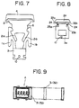
- Figs. 7 and 8 respectively show second and third embodiments of the present invention.
- the distal end portion of the outer barrier member 2 has two arms 21a and 21b which correspond with the two arms 11a and 11b of the fixing barrier member 3 and give the outer barrier member 2 resilience. Accordingly, when the two barrier members 2 and 3 are engaged, the outer barrier member 2 provides an outward resilient force.
- the outer barrier member 2 has two arms 22a, and 22b and distal end projections 23a, and 23b; the fixing barrier member 3 is provided with engagement projections 24a and 24b in contrast to the arrangement shown in Figs. 1 and 2.
Landscapes
- Engineering & Computer Science (AREA)
- Power Engineering (AREA)
- Switch Cases, Indication, And Locking (AREA)
- Push-Button Switches (AREA)
Claims (8)
- Barriereanordnung zum Abteilen einer Öffnung in einer Tafel (1), um benachbarte Bestandteile (A) zu trennen, die in einer Abfolge in der Öffnung montiert sind, wobei die Anordnung umfaßt:
ein erstes Barriereelement (2) zum Einfügen in die genannte Öffnung von einer Seite der Tafel (1), dadurch gekennzeichnet, daß ein zweites Barriereelement (3) zum Einfügen zwischen den genannten benachbarten Bestandteilen von der anderen Seite der Tafel (1) vorhanden ist, wobei das erste und das zweite Element miteinander in Eingriff bringbar sind. - Barriereanordnung nach Anspruch 1, worin das zweite Barriereelement (3) ein Paar elastischer Klauen (11a, 11b) aufweist, die so ausgebildet sind, daß sie in entsprechende Flansche (8a, 8b) eingreifen, die vom ersten Barriereelement (2) nach außen vorspringen.
- Barriereanordnung nach Anspruch 2, worin das erste Barriereelement (2) einen Hals (6) und einen vergrößerten Kopf (4) aufweist, und die genannten Flansche (8a, 8b) von gegenüberliegenden Seiten des Halses (6) vorragen und die Breite des vom Kopf (4) entfernten Teils des Halses (6) kleiner ist als die Breite zwischen den Flanschen (8a, 8b) und die Arme (11a,11b) mit den Flanschen (8a,8b) in Eingriff sind, um zumindest einen Teil des Halses zwischen den Armen (11a, 11b) festzuhalten.
- Barriereanordnung nach Anspruch 1, worin das zweite Barriereelement (3) ein Paar elastischer Arme (11a, 11b) aufweist, die so ausgebildet sind, daß sie in ein Paar Flansche (8a, 8b) eingreifen, die von einem Hals (6) des ersten Barriereelements (2) nach außen ragen.
- Barriereanordnung nach einem der vorhergehenden Ansprüche, worin das erste Barriereelement (2) einen Kopf (4) zum Anliegen an einer Oberfläche der Montagetafel und einen Hals (6) zum Hindurchragen durch die Öffnung in der Tafel (1) aufweist, und worin das zweite Barriereelement (3) Rillen zum Führen und Aufnehmen des Halses (6) aufweist.
- Vorrichtung, die eine Tafel mit einer Öffnung darin und eine Vielzahl von Bestandteilen in einer Abfolge in der Öffnung montiert aufweist, wobei eine Barriereanordnung nach einem der vorhergehenden Ansprüche mit dem ersten und dem zweiten Element in Eingriff zwischen benachbarten Steuervorrichtungen montiert ist.
- Vorrichtung nach Anspruch 6, worin das zweite Barriereelement (3) zumindest einen vorragenden Zapfen (10) aufweist, der in eine Ausnehmung (19) im/in den benachbarten Bestandteil(en) (A) eingreift.
- Vorrichtung nach Anspruch 7, worin ein Paar elastischer Vorsprünge (19a, 19b) innerhalb der Ausnehmung (19) vorgesehen ist, um den Zapfen (10) zu halten.
Applications Claiming Priority (4)
| Application Number | Priority Date | Filing Date | Title |
|---|---|---|---|
| JP39780/87U | 1987-03-17 | ||
| JP3978087U JPS63146924U (de) | 1987-03-17 | 1987-03-17 | |
| JP9560987U JPH0629859Y2 (ja) | 1987-06-22 | 1987-06-22 | 制御機器のバリア取付構造 |
| JP95609/87U | 1987-06-22 |
Publications (3)
| Publication Number | Publication Date |
|---|---|
| EP0283258A2 EP0283258A2 (de) | 1988-09-21 |
| EP0283258A3 EP0283258A3 (en) | 1989-05-10 |
| EP0283258B1 true EP0283258B1 (de) | 1993-05-26 |
Family
ID=26379169
Family Applications (1)
| Application Number | Title | Priority Date | Filing Date |
|---|---|---|---|
| EP88302279A Expired - Lifetime EP0283258B1 (de) | 1987-03-17 | 1988-03-16 | Scheidungsaufbau zum Aufteilen von Komponenten |
Country Status (3)
| Country | Link |
|---|---|
| US (1) | US4883929A (de) |
| EP (1) | EP0283258B1 (de) |
| DE (1) | DE3881244T2 (de) |
Families Citing this family (1)
| Publication number | Priority date | Publication date | Assignee | Title |
|---|---|---|---|---|
| US5230422A (en) * | 1990-11-05 | 1993-07-27 | Allen-Bradley Company, Inc. | Operator/cartridge assembly |
Family Cites Families (4)
| Publication number | Priority date | Publication date | Assignee | Title |
|---|---|---|---|---|
| US2935653A (en) * | 1958-04-30 | 1960-05-03 | Honeywell Regulator Co | Mounting arrangement for electrical device |
| US3049646A (en) * | 1959-04-03 | 1962-08-14 | Honeywell Regulator Co | Mounting arrangement for an electrical device |
| US3091795A (en) * | 1960-08-05 | 1963-06-04 | Gilbert G Budwig | Grommet |
| US3394909A (en) * | 1966-07-12 | 1968-07-30 | Robertshaw Controls Co | Single and gang mounts for electric casings |
-
1988
- 1988-03-09 US US07/166,089 patent/US4883929A/en not_active Expired - Lifetime
- 1988-03-16 EP EP88302279A patent/EP0283258B1/de not_active Expired - Lifetime
- 1988-03-16 DE DE88302279T patent/DE3881244T2/de not_active Expired - Lifetime
Non-Patent Citations (1)
| Title |
|---|
| OMRON CONTROL COMPONENTS 80-81, pages 100 & 107 (Omron Electronics Inc). * |
Also Published As
| Publication number | Publication date |
|---|---|
| EP0283258A2 (de) | 1988-09-21 |
| US4883929A (en) | 1989-11-28 |
| DE3881244T2 (de) | 1993-12-02 |
| EP0283258A3 (en) | 1989-05-10 |
| DE3881244D1 (de) | 1993-07-01 |
Similar Documents
| Publication | Publication Date | Title |
|---|---|---|
| US10725248B2 (en) | Fiber optic receptacle with integrated device therein incorporating a behind-the-wall fiber optic receptacle | |
| US4674814A (en) | Connector assembly | |
| KR100247513B1 (ko) | 컴퓨터의 섀시 어셈블리 | |
| JP4614628B2 (ja) | 表示ラベル取付構造 | |
| EP0623471A2 (de) | Verfahren und Vorrichtung zum Verhindern unbeabsichtigten Gebrauchs von Druckpatronen | |
| JP2000304976A (ja) | 光ファイバコネクタスリーブ | |
| EP0470471A2 (de) | Paneel-Befestigungsbügel | |
| US6159031A (en) | Retention mechanism that can be used with different electronic assemblies | |
| EP0961362B1 (de) | Montagestruktur für elektrischen Steckverbinder | |
| EP3708031B1 (de) | Anschlussvorrichtung | |
| US7483263B2 (en) | Computer enclosure | |
| US11433829B2 (en) | Fitting structure | |
| KR100346711B1 (ko) | 프로젝션 텔레비젼 | |
| DE3516754A1 (de) | Befestigungsanordnung fuer eine schaltungskarte | |
| US5478246A (en) | Guiding and protecting housing for memory card connector | |
| EP0283258A2 (de) | Scheidungsaufbau zum Aufteilen von Komponenten | |
| US4214801A (en) | Fuse holder with insertion ramp | |
| EP0978742B1 (de) | Besfestigungsvorrichtung für eine optische Faser zur Kopplung mit einem optischen Kommunikationsmodul | |
| GB2344085A (en) | Attachment structure between a vehicle bumper and grille | |
| US20010032736A1 (en) | Circuit board holder | |
| EP0210686A2 (de) | Elektrischer Steckverbinder mit Montierglied | |
| EP0558331A1 (de) | Abnehmbares Gerät für Autoradio | |
| JP3294635B2 (ja) | プリント基板の誤挿入防止機構を備えたコネクタ構造とそれを備えた電子装置 | |
| WO1998038715A1 (en) | Electrical outlet having panel mount latches | |
| US6775142B1 (en) | Magnetic disk drive storage system |
Legal Events
| Date | Code | Title | Description |
|---|---|---|---|
| PUAI | Public reference made under article 153(3) epc to a published international application that has entered the european phase |
Free format text: ORIGINAL CODE: 0009012 |
|
| AK | Designated contracting states |
Kind code of ref document: A2 Designated state(s): AT BE CH DE ES FR GB GR IT LI LU NL SE |
|
| PUAL | Search report despatched |
Free format text: ORIGINAL CODE: 0009013 |
|
| AK | Designated contracting states |
Kind code of ref document: A3 Designated state(s): AT BE CH DE ES FR GB GR IT LI LU NL SE |
|
| RAP1 | Party data changed (applicant data changed or rights of an application transferred) |
Owner name: OMRON TATEISI ELECTRONICS CO. |
|
| 17P | Request for examination filed |
Effective date: 19891027 |
|
| 17Q | First examination report despatched |
Effective date: 19911015 |
|
| RBV | Designated contracting states (corrected) |
Designated state(s): DE FR GB IT |
|
| GRAA | (expected) grant |
Free format text: ORIGINAL CODE: 0009210 |
|
| AK | Designated contracting states |
Kind code of ref document: B1 Designated state(s): DE FR GB IT |
|
| REF | Corresponds to: |
Ref document number: 3881244 Country of ref document: DE Date of ref document: 19930701 |
|
| ITF | It: translation for a ep patent filed | ||
| ET | Fr: translation filed | ||
| PLBE | No opposition filed within time limit |
Free format text: ORIGINAL CODE: 0009261 |
|
| STAA | Information on the status of an ep patent application or granted ep patent |
Free format text: STATUS: NO OPPOSITION FILED WITHIN TIME LIMIT |
|
| 26N | No opposition filed | ||
| REG | Reference to a national code |
Ref country code: GB Ref legal event code: 746 Effective date: 19981118 |
|
| REG | Reference to a national code |
Ref country code: FR Ref legal event code: D6 |
|
| REG | Reference to a national code |
Ref country code: GB Ref legal event code: IF02 |
|
| PGFP | Annual fee paid to national office [announced via postgrant information from national office to epo] |
Ref country code: FR Payment date: 20060308 Year of fee payment: 19 |
|
| PGFP | Annual fee paid to national office [announced via postgrant information from national office to epo] |
Ref country code: GB Payment date: 20060315 Year of fee payment: 19 |
|
| PGFP | Annual fee paid to national office [announced via postgrant information from national office to epo] |
Ref country code: IT Payment date: 20060331 Year of fee payment: 19 |
|
| PGFP | Annual fee paid to national office [announced via postgrant information from national office to epo] |
Ref country code: DE Payment date: 20070308 Year of fee payment: 20 |
|
| GBPC | Gb: european patent ceased through non-payment of renewal fee |
Effective date: 20070316 |
|
| REG | Reference to a national code |
Ref country code: FR Ref legal event code: ST Effective date: 20071130 |
|
| PG25 | Lapsed in a contracting state [announced via postgrant information from national office to epo] |
Ref country code: GB Free format text: LAPSE BECAUSE OF NON-PAYMENT OF DUE FEES Effective date: 20070316 |
|
| PG25 | Lapsed in a contracting state [announced via postgrant information from national office to epo] |
Ref country code: FR Free format text: LAPSE BECAUSE OF NON-PAYMENT OF DUE FEES Effective date: 20070402 |
|
| PG25 | Lapsed in a contracting state [announced via postgrant information from national office to epo] |
Ref country code: IT Free format text: LAPSE BECAUSE OF NON-PAYMENT OF DUE FEES Effective date: 20070316 |