EP0282858B1 - Mechanical energy buffer without any latching force - Google Patents
Mechanical energy buffer without any latching force Download PDFInfo
- Publication number
- EP0282858B1 EP0282858B1 EP88103493A EP88103493A EP0282858B1 EP 0282858 B1 EP0282858 B1 EP 0282858B1 EP 88103493 A EP88103493 A EP 88103493A EP 88103493 A EP88103493 A EP 88103493A EP 0282858 B1 EP0282858 B1 EP 0282858B1
- Authority
- EP
- European Patent Office
- Prior art keywords
- rod
- axis
- spring
- cage
- roller
- Prior art date
- Legal status (The legal status is an assumption and is not a legal conclusion. Google has not performed a legal analysis and makes no representation as to the accuracy of the status listed.)
- Expired - Lifetime
Links
- 230000008878 coupling Effects 0.000 claims abstract description 6
- 238000010168 coupling process Methods 0.000 claims abstract description 6
- 238000005859 coupling reaction Methods 0.000 claims abstract description 6
- 238000004146 energy storage Methods 0.000 claims abstract description 5
- 230000009471 action Effects 0.000 claims description 4
- 238000005096 rolling process Methods 0.000 description 5
- 230000007246 mechanism Effects 0.000 description 4
- 230000008901 benefit Effects 0.000 description 3
- 230000009467 reduction Effects 0.000 description 2
- 230000006835 compression Effects 0.000 description 1
- 238000007906 compression Methods 0.000 description 1
- 238000006073 displacement reaction Methods 0.000 description 1
- 230000003100 immobilizing effect Effects 0.000 description 1
Images
Classifications
-
- H—ELECTRICITY
- H01—ELECTRIC ELEMENTS
- H01H—ELECTRIC SWITCHES; RELAYS; SELECTORS; EMERGENCY PROTECTIVE DEVICES
- H01H3/00—Mechanisms for operating contacts
- H01H3/22—Power arrangements internal to the switch for operating the driving mechanism
- H01H3/30—Power arrangements internal to the switch for operating the driving mechanism using spring motor
- H01H3/3031—Means for locking the spring in a charged state
- H01H2003/3036—Means for locking the spring in a charged state using of balls or rollers in the locking device
-
- H—ELECTRICITY
- H01—ELECTRIC ELEMENTS
- H01H—ELECTRIC SWITCHES; RELAYS; SELECTORS; EMERGENCY PROTECTIVE DEVICES
- H01H3/00—Mechanisms for operating contacts
- H01H3/22—Power arrangements internal to the switch for operating the driving mechanism
- H01H3/30—Power arrangements internal to the switch for operating the driving mechanism using spring motor
- H01H3/3052—Linear spring motors
-
- Y—GENERAL TAGGING OF NEW TECHNOLOGICAL DEVELOPMENTS; GENERAL TAGGING OF CROSS-SECTIONAL TECHNOLOGIES SPANNING OVER SEVERAL SECTIONS OF THE IPC; TECHNICAL SUBJECTS COVERED BY FORMER USPC CROSS-REFERENCE ART COLLECTIONS [XRACs] AND DIGESTS
- Y10—TECHNICAL SUBJECTS COVERED BY FORMER USPC
- Y10T—TECHNICAL SUBJECTS COVERED BY FORMER US CLASSIFICATION
- Y10T74/00—Machine element or mechanism
- Y10T74/11—Tripping mechanism
Definitions
- the present invention relates to a mechanical energy storage device, by means of springs and intended in particular for the actuation of an electric circuit breaker.
- circuit breakers It is known that the mechanical actuation of circuit breakers is carried out for example by means of a compression spring. The energy necessary for the operation is then stored in the banded spring. The spring is kept bandaged by a more or less complex hooking device, which necessarily comprises a hooking member immobilizing a wheel or a cam.
- This document describes a spring device, controlled by pulse, for the operation of electrical devices, in particular switch and disconnector, in a long time relative to the duration of said pulse.
- This device comprises a spring driving, via a cable and a cam, the trigger control shaft. Its rearming is carried out using a shaft provided with a non-return means comprising in particular a ratchet wheel cooperating with a ratchet carrying at its end a hooking roller and driving, by means of a reduction kinematic chain. , said control shaft in the opposite direction to said triggering.
- the pulse causes the permanent locking of the non-return means and authorizes the completion of the trigger.
- the fastening member and the wheel exert a mutual force between them which it is necessary to overcome to unlock the wheel and allow the spring to relax. This effort is all the greater the greater the energy stored in the springs. The greater this effort, the greater the energy of the trigger mechanism to overcome it.
- Document FR-A-2,319,188 discloses a coupling mechanism comprising two springs which can successively relax, thanks to a ball locking member which authorizes the action of the second spring only when the first spring has finished his relaxation.
- this mechanism comprises a rod on which a cage of balls slides. These balls can either penetrate into a groove of the rod (case of attachment between the cage and the rod), or move radially to be housed in a flared part of a fixed sleeve (case of release from the cage and the rod and hooking between the cage and the sleeve).
- the rod is therefore driven first by a single spring and then, after detachment between cage and sleeve, by the action of the two springs.
- a similar ball locking member is known from document DE-A-29 43 104.
- Such a device has the great advantage of being very simple to implement.
- first rod 10 provided at its first end with a flange 11, and at its second end with a nozzle 12.
- This first rod 10 is slidably mounted along a longitudinal axis ⁇ inside d 'a bore 13 pierced in a cover 15 which closes a fixed cage 16 at its first end: this cage is here square in shape, and has as axis of symmetry the axis ⁇ . It ends at its second end with a flared part 28.
- the first end of this rod 10 is secured to hooking means constituted here by a rod 18, for controlling the circuit breaker for example, provided with a transverse bore 19 in which, in the engaged position, is introduced a hooking member 100 controlled, for example, by an electromagnet 121 which keeps the first rod 10 in a fixed position when the first spring 17 is banded.
- hooking means constituted here by a rod 18, for controlling the circuit breaker for example, provided with a transverse bore 19 in which, in the engaged position, is introduced a hooking member 100 controlled, for example, by an electromagnet 121 which keeps the first rod 10 in a fixed position when the first spring 17 is banded.
- a second rod 20 is provided at its first end which faces the second end of the first rod, with a flange 21.
- This second rod 20 is slidably mounted along the axis ⁇ , inside a bore 22 drilled in a fixed frame 23.
- a second spring 34 with a flange for example, is arranged around this rod 20 while being fixed on the one hand to the flange 21, and on the other hand to the frame 23.
- Two arms 24 and 24A provided at their first ends with bearings 25, 26 and 25A, 26A, for example with balls, whose axes of rotation 29 and 29A are perpendicular to the axis ⁇ , are mobile, at their second ends, around two axes 27 and 27A, in directions parallel to axes 29 and 29A, which are located symmetrically with respect to the axis ⁇ and integral with the external part of the flange 21.
- the end piece 12 is formed by several symmetrical bearing surfaces with respect to the axis ⁇ , are successively: two first planar bearing surfaces 31 and 31A parallel to the rolling surfaces 30 and 30A, two inclined bearing surfaces 33 and 33A towards the ⁇ axis, and two second planar bearings 32 and 32A parallel to the first.
- the relative ball bearings at each axis 29 (29A) respectively consist of two first bearings 25 (25A) which roll on the rolling surface 30 (30A) inside the cage 16, surrounding a second bearing 26 (26A), of smaller diameter, which rolls on the outer surface of the endpiece 12, that is to say on the surfaces 31, 33 and 32 (31A, 33A and 32A).
- the second spring 34 is self-locked: in fact the first bearings 25 and 25A rest inside the flared part 28 of the cage 16, and the second bearings 26 and 26A rest on the first flat bearings 31 and 31A respectively, which prevents movement of these bearings in the direction 40 shown in FIG. 2.
- the first spring 17 begins to relax by driving the rod 10 in the direction of the arrow 40. Without any thrust which would be due to the second spring 34, the bearings 25, 25A, 26, 26A pass from their first position as shown in Figure 1, to the second position shown in Figure 2. The second bearings 26 and 26A, part of the outer surface then rests on the inclined surfaces 33 and 33A used to transmit to the first rod 10 the thrust of the second spring 34 .
- the device of the invention therefore has the great advantage of allowing the storage of a surplus of mechanical energy due to the second spring 34 without the latter acting on the attachment. In fact, in the engaged position, only the first spring 17 presses on the coupling, the second spring 34 being blocked by the rolling system.
- the invention therefore makes it possible to simplify the mechanical controls of such a device: the thrust due to the first spring being weak, the attachment is simplified and can be direct, which makes it possible to avoid stages of reduction of the stored energy . In addition, this energy can be very important.
- the device of the invention can be used to perform the switching on and off functions of mechanical controls.
Landscapes
- Springs (AREA)
- Driving Mechanisms And Operating Circuits Of Arc-Extinguishing High-Tension Switches (AREA)
- Supporting Of Heads In Record-Carrier Devices (AREA)
- Materials For Medical Uses (AREA)
- Hybrid Cells (AREA)
- Battery Mounting, Suspending (AREA)
- Other Liquid Machine Or Engine Such As Wave Power Use (AREA)
- Prostheses (AREA)
- Current-Collector Devices For Electrically Propelled Vehicles (AREA)
- Mechanical Operated Clutches (AREA)
- Load-Engaging Elements For Cranes (AREA)
- Bearings For Parts Moving Linearly (AREA)
Abstract
Description
La présente invention est relative à un dispositif de stockage d'énergie mécanique, au moyen de ressorts et destiné en particulier à l'actionnement d'un disjoncteur électrique.The present invention relates to a mechanical energy storage device, by means of springs and intended in particular for the actuation of an electric circuit breaker.
On sait que l'actionnement mécanique des disjoncteurs est réalisé par exemple au moyen d'un ressort de compression. L'énergie nécessaire à la manoeuvre est alors stockée dans le ressort bandé. Le ressort est maintenu bandé grâce à un dispositif d'accrochage plus ou moins complexe, qui comprend nécessairement un organe d'accrochage immobilisant une roue ou une came.It is known that the mechanical actuation of circuit breakers is carried out for example by means of a compression spring. The energy necessary for the operation is then stored in the banded spring. The spring is kept bandaged by a more or less complex hooking device, which necessarily comprises a hooking member immobilizing a wheel or a cam.
On se référera à cet égard au document FR-A-1.588.485. Ce document décrit un dispositif à ressort, commandé par impulsion, pour la manoeuvre d'appareils électriques, notamment interrupteur et sectionneur, en un temps long par rapport à la durée de ladite impulsion. Ce dispositif comporte un ressort entraînant, par l'intermédiaire d'un câble et d'une came, l'arbre de commande du déclenchement. Son réarmement est effectué à l'aide d'un arbre muni d'un moyen antiretour comportant notamment une roue à rochet coopérant avec un cliquet portant à son extrémité un galet d'accrochage et entraînant, par l'intermédiaire d'une chaîne cinématique démultiplicatrice, ledit arbre de commande en sens inverse dudit déclenchement. L'impulsion provoque le verrouillage permanent du moyen antiretour et autorise l'achèvement du déclenchement.Reference is made in this regard to document FR-A-1,588,485. This document describes a spring device, controlled by pulse, for the operation of electrical devices, in particular switch and disconnector, in a long time relative to the duration of said pulse. This device comprises a spring driving, via a cable and a cam, the trigger control shaft. Its rearming is carried out using a shaft provided with a non-return means comprising in particular a ratchet wheel cooperating with a ratchet carrying at its end a hooking roller and driving, by means of a reduction kinematic chain. , said control shaft in the opposite direction to said triggering. The pulse causes the permanent locking of the non-return means and authorizes the completion of the trigger.
L'organe d'accrochage et la roue exercent entre eux un effort mutuel qu'il est nécessaire de vaincre pour débloquer la roue et permettre la détente du ressort. Cet effort est d'autant plus grand que l'énergie stockée dans les ressorts est importante. Plus cet effort est important, plus l'énergie du mécanisme de déclenchement doit être grande pour le vaincre.The fastening member and the wheel exert a mutual force between them which it is necessary to overcome to unlock the wheel and allow the spring to relax. This effort is all the greater the greater the energy stored in the springs. The greater this effort, the greater the energy of the trigger mechanism to overcome it.
On connaît par le document FR-A-2.319.188 un mécanisme d'accouplement comprenant deux ressorts pouvant se détendre successivement, grâce à un organe de blocage à billes qui n'autorise l'action du second ressort que lorsque le premier ressort a terminé sa détente.Document FR-A-2,319,188 discloses a coupling mechanism comprising two springs which can successively relax, thanks to a ball locking member which authorizes the action of the second spring only when the first spring has finished his relaxation.
A cet effet, ce mécanisme comporte une tige sur laquelle glisse une cage de billes. Ces billes peuvent soit pénétrer dans une rainure de la tige (cas d'accrochage entre la cage et la tige), soit se déplacer radialement pour se loger dans une partie évasée d'un manchon fixe (cas de décrochage entre la cage et la tige et accrochage entre la cage et le manchon). Lors de la décharge des ressorts, la tige est donc entraînée d'abord par un seul ressort et puis, après décrochage entre cage et manchon, par l'action des deux ressorts.To this end, this mechanism comprises a rod on which a cage of balls slides. These balls can either penetrate into a groove of the rod (case of attachment between the cage and the rod), or move radially to be housed in a flared part of a fixed sleeve (case of release from the cage and the rod and hooking between the cage and the sleeve). During the discharge of the springs, the rod is therefore driven first by a single spring and then, after detachment between cage and sleeve, by the action of the two springs.
Un organe de blocage à billes similaire est connu par le document DE-A-29 43 104.A similar ball locking member is known from document DE-A-29 43 104.
Il est souhaitable d'utiliser un mécanisme à faible énergie.It is desirable to use a low energy mechanism.
IL est également souhaité de pouvoir augmenter la quantité d'énergie stockée (par exemple en utilisant plusieurs ressorts et/ou des ressorts plus puissants), sans augmenter l'effort d'accrochage.It is also desired to be able to increase the amount of energy stored (for example by using several springs and / or more powerful springs), without increasing the attachment force.
Ce but est atteint par le dispositif tel que défini par le revendication 1, qui permet de stocker une énergie mécanique avec une force d'accrochage très faible.This object is achieved by the device as defined by claim 1, which makes it possible to store mechanical energy with a very low gripping force.
Un tel dispositif présente le grand avantage d'être d'une grande simplicité de mise en oeuvre.Such a device has the great advantage of being very simple to implement.
Les avantages de l'invention ressortiront d'ailleurs de la description suivante d'un exemple de réalisation faisant référence aux figures annexées sur lesquelles:
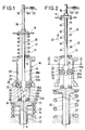
- la figure 1 est une vue schématique du dispositif de l'invention, prêt à fonctionner, les ressorts étant bandés ;
- la figure 2 est une vue schématique du même dispositif en cours de fonctionnement ;
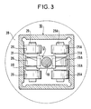
- la figure 3 est une vue en coupe selon la ligne III-III de la figure 2.
- Figure 1 is a schematic view of the device of the invention, ready to operate, the springs being bandaged;
- Figure 2 is a schematic view of the same device during operation;
- Figure 3 is a sectional view along line III-III of Figure 2.
Dans la figure 1, on distingue une première tige 10 munie à sa première extrémité d'une collerette 11, et à sa seconde extrémité d'un embout 12. Cette première tige 10 est montée coulissante selon un axe longitudinal Δ à l'intérieur d'un alésage 13 percé dans un couvercle 15 qui ferme une cage fixe 16 à sa première extrémité: cette cage est ici de forme carrée, et a pour axe de symétrie l'axe Δ. Elle se termine en sa deuxième extrémité par une partie évasée 28.In Figure 1, there is a
Un premier ressort 17, à boudin par exemple, est disposé autour de cette tige 10, en étant fixé d'une part à la collerette 11 et d'autre part à la partie extérieure de la cage 16.A
La première extrémité de cette tige 10 est solidaire de moyens d'accrochage constitués ici d'une tige 18, de commande de disjoncteur par exemple, munie d'un alésage transversal 19 dans lequel, en position enclenchée, est introduit un organe d'accrochage 100 commandé, par exemple, par un électro-aimant 121 qui permet de maintenir la première tige 10 en position fixe lorsque le premier ressort 17 est bandé.The first end of this
Une seconde tige 20 est munie à sa première extrémité qui fait face à la seconde extrémité de la première tige, d'une collerette 21. Cette seconde tige 20 est montée coulissante selon l'axe Δ, à l'intérieur d'un alésage 22 percé dans un bâti fixe 23.A
Un second ressort 34, à boudin par exemple, est disposé autour de cette tige 20 en étant fixé d'une part à la collerette 21, et d'autre part au bâti 23.A
Deux bras 24 et 24A, munis à leurs premières extrémités de roulements 25, 26 et 25A, 26A, à billes par exemple, dont les axes de rotation 29 et 29A sont perpendiculaires à l'axe Δ, sont mobiles, en leurs secondes extrémités, autour de deux axes 27 et 27A, de directions parallèles aux axes 29 et 29A, qui sont situés symétriquement par rapport à l'axe Δ et solidaires de la partie extérieure de la collerette 21.Two
Les extrémités libres de la première 10 et de la seconde tige 20 se faisant face, les roulements 25, 26 et 25A, 26A peuvent rouler entre l'embout 12 et respectivement deux portées 30 et 30A de la cage 16 qui sont planes, parallèles et symétriques par rapport à l'axe Δ. Ces portées forment donc deux surfaces de roulement ou de guidage qui se terminent par la partie évasée 28.The free ends of the first 10 and of the
Comme représenté à la figure 1, l'embout 12 est formé de plusieurs portées symétriques par rapport à l'axe Δ, soient successivement : deux premières portées planes 31 et 31A parallèles aux surfaces de roulement 30 et 30A, deux portées 33 et 33A inclinées vers l'axe Δ, et deux secondes portées planes 32 et 32A parallèles aux premières.As shown in FIG. 1, the
Comme représenté à la figure 3, les roulements à billes relatifs à chaque axe 29 (29A) sont respectivement constitués de deux premiers roulements 25 (25A) qui roulent sur la surface de roulement 30 (30A) intérieure à la cage 16, entourant un second roulement 26 (26A), de plus petit diamètre, qui roule sur la surface extérieure de l'embout 12 c'est-à-dire sur les portées 31, 33 et 32 (31A, 33A et 32A).As shown in Figure 3, the relative ball bearings at each axis 29 (29A) respectively consist of two first bearings 25 (25A) which roll on the rolling surface 30 (30A) inside the
En position d'enclenchement, comme représenté à la figure 1, le ressort 17 est comprimé de telle sorte que l'organe d'accrochage 100 soit situé à l'intérieur de l'alésage 19.In the latching position, as shown in FIG. 1, the
Dans cette position le second ressort 34 est auto-bloqué :
en effet les premiers roulements 25 et 25A reposent à l'intérieur de la partie évasée 28 de la cage 16, et les seconds roulements 26 et 26A reposent sur les premières portées planes respectivement 31 et 31A, ce qui interdit un mouvement de ces roulements dans la direction 40 représentée à la figure 2.In this position the
in fact the
En cours de fonctionnement comme représenté aux figures 2 et 3, les ressorts 17 et 34 se sont détendus. Les quatre premiers roulements 25 (25A) reposent alors sur la surface de roulement 30 (30A), et le second roulement 26 (26A) sur la portée inclinée 33 (33A).During operation as shown in Figures 2 and 3, the
Lors du déclenchement c'est-à-dire du passage d'une position à l'autre, la bobine 121 est alimentée, l'organe d'accrochage 100 est alors libéré.When triggering, that is to say the passage from one position to another, the
Le premier ressort 17 commence à se détendre en entraînant la tige 10 dans le sens de la flèche 40. Sans aucune poussée qui serait dûe au second ressort 34, les roulements 25, 25A, 26, 26A passent de leur première position telle que représentée à la figure 1, vers la seconde position représentée à la figure 2. Les seconds roulements 26 et 26A dont une partie de la surface extérieure repose alors sur les portées inclinées 33 et 33A permettent de transmettre à la première tige 10 la poussée du second ressort 34.The
Les poussées de ces seconds roulements 26 et 26A sur les portées de l'embout 12 freinent très peu le mouvement initial de la tige 10 puisqu'il y a déplacement des premiers roulements 25 et 25A sur les surfaces 30 et 30A.The thrusts of these
Le dispositif de l'invention présente donc le grand avantage de permettre le stockage d'un surplus d'énergie mécanique dûe au second ressort 34 sans que cette dernière n'agisse sur l'accrochage. En effet, en position enclenchée, seul le premier ressort 17 appuie sur l'accrochage, le second ressort 34 étant bloqué grâce au système à roulement.The device of the invention therefore has the great advantage of allowing the storage of a surplus of mechanical energy due to the
L'invention permet donc, de simplifier les commandes mécaniques d'un tel dispositif : la poussée dûe au premier ressort étant faible, l'accrochage est simplifié et peut être direct ce qui permet d'éviter des étages de démultiplication de l'énergie emmagasinée. De plus cette énergie peut être très importante.The invention therefore makes it possible to simplify the mechanical controls of such a device: the thrust due to the first spring being weak, the attachment is simplified and can be direct, which makes it possible to avoid stages of reduction of the stored energy . In addition, this energy can be very important.
Le dispositif de l'invention peut être utilisé pour réaliser des fonctions d'enclenchement et de déclenchement de commandes mécaniques.The device of the invention can be used to perform the switching on and off functions of mechanical controls.
Claims (8)
- A mechanical energy storage device employing a small latching force adapted to actuate a circuit-breaker which is provided with an actuating rod (18) mounted to slide along a longitudinal axis Δ and being provided with a transverse groove (19) in which, in the loaded position, is introduced a latching member (100) controlled by an electromagnet (121), said actuating rod being extended along the longitudinal axis (Δ) by a first rod (10) subjected to the axial action of a first spring (17) whose axis coincides with said longitudinal axis (Δ), and connected axially to the free end of a second rod (20) by coupling and locking means, said second rod (20) being subjected to the axial action of a second spring (24), with the coupling an locking means being provided with at least one arm (24, 24A) having at a first end a bearing means, constituted of at least one roller (25, 25A, 26, 26A), the axis of rotation of said rollers being perpendicular to the axis (Δ), said arm being movable at a second end about an axis (27, 27A) extending parallel to the axis of rotation of each roller (25, 25A, 26, 26A) and fixed to the free end of the second rod (20), and with a fixed cage (16) provided with at least one running surface (30, 30A) extending parallel to the direction of said axis (Δ) and to the axes (29, 29A) of each roller, which cage terminates in at least one flared portion (28) facing the second rod (20), with the second end of the first rod (10) comprising an end piece (12) provided with at least a first plane portion (31, 31A) parallel to the running surface (30, 30A) and whose free end tapers in such a manner that in the loaded position of the latching member (100) each of the rollers is contained between said plane surface (31, 31A) and the flared portion (28) of the cage (16), so as to lock the second spring (34).
- A device according to claim 1, characterized in that the end piece (12) of the first rod (10) includes a second plane bearing surface (32, 32A) parallel to the first plane surface (31, 31A) and separated from the first plane surface by a plane surface (33, 33A) which slopes towards the axis (Δ).
- A device according to claim 1 or 2, characterized in that said bearing means is constituted of at least one first roller (25, 25A) which runs over a running surface (30, 30A), and of a second roller (26, 26A) capable of running over said plane surfaces of the end piece (12) of the first rod (10).
- A device according to claim 3, characterized in that there are two said first rollers (25, 25A) which are arranged to encompass said second roller (26, 26A) which has a smaller diameter.
- A device according to any one of the preceding claims, characterized in that said coupling and locking means comprise two arms (24, 24A) which are pivotally mounted on the free end of the second rod (20) by means of rotary axes (27, 27A) disposed symmetrically relative to said longitudinal axis (Δ), and in that the cage (16) and the end piece (12) take respectively the form of symmetrical structures relative to the longitudinal axis (Δ).
- A device according to any one of the preceding claims, characterized in that the cage (16) is closed at its end facing the first rod (10) by a cover pierced by a bore (13) centered on said longitudinal axis (Δ), with said first rod (10) being slidable in said bore.
- A device according to claim 6, characterized in that the first spring (17) is a coil spring disposed around the first rod (10) between a collar (11) carried by the first rod (10) end extending perpendicularly thereto, and the cover of the cage (16).
- A device according to any one of the preceding claims, characterized in that the second spring (34) is a coil spring disposed around the second rod (20) between a collar (21) carried by the free end thereof and a fixed frame (23) provided with a bore (22) through which said rod slides.
Priority Applications (1)
| Application Number | Priority Date | Filing Date | Title |
|---|---|---|---|
| AT88103493T ATE89434T1 (en) | 1987-03-17 | 1988-03-07 | MECHANICAL ENERGY STORAGE WITHOUT LOCKING FORCE. |
Applications Claiming Priority (2)
| Application Number | Priority Date | Filing Date | Title |
|---|---|---|---|
| FR8703637A FR2612570A1 (en) | 1987-03-17 | 1987-03-17 | MECHANICAL ENERGY STORAGE DEVICE HAVING NULL ACCELERATION STRENGTH |
| FR8703637 | 1987-03-17 |
Publications (2)
| Publication Number | Publication Date |
|---|---|
| EP0282858A1 EP0282858A1 (en) | 1988-09-21 |
| EP0282858B1 true EP0282858B1 (en) | 1993-05-12 |
Family
ID=9349065
Family Applications (1)
| Application Number | Title | Priority Date | Filing Date |
|---|---|---|---|
| EP88103493A Expired - Lifetime EP0282858B1 (en) | 1987-03-17 | 1988-03-07 | Mechanical energy buffer without any latching force |
Country Status (10)
| Country | Link |
|---|---|
| US (1) | US4841788A (en) |
| EP (1) | EP0282858B1 (en) |
| JP (1) | JPS63252326A (en) |
| CN (1) | CN1010045B (en) |
| AT (1) | ATE89434T1 (en) |
| BR (1) | BR8801194A (en) |
| CA (1) | CA1292030C (en) |
| DE (1) | DE3880863T2 (en) |
| ES (1) | ES2040768T3 (en) |
| FR (1) | FR2612570A1 (en) |
Families Citing this family (13)
| Publication number | Priority date | Publication date | Assignee | Title |
|---|---|---|---|---|
| JPH0450058A (en) * | 1990-06-18 | 1992-02-19 | Takata Kk | Pretensioner for seat belt device |
| US6722216B2 (en) * | 2001-07-17 | 2004-04-20 | Ansul Incorporated | Booster actuator |
| FR2836277B1 (en) * | 2002-02-19 | 2004-04-16 | Alstom | SPRING DRIVE MECHANISM FOR RECLINKED MOTION CIRCUIT BREAKER |
| US6657150B1 (en) * | 2002-06-14 | 2003-12-02 | Eaton Corporation | Shorting switch and system to eliminate arcing faults in power distribution equipment |
| US7115828B2 (en) * | 2004-04-30 | 2006-10-03 | Southern States, Inc. | Internally switched electric power interrupter |
| JP4933208B2 (en) * | 2006-09-29 | 2012-05-16 | 河村電器産業株式会社 | Circuit breaker |
| GB0622385D0 (en) * | 2006-11-10 | 2006-12-20 | Rolls Royce Plc | Coupling |
| KR101132909B1 (en) * | 2011-02-08 | 2012-04-03 | 엘에스산전 주식회사 | Spring actuator for circuit breaker |
| US9038742B2 (en) * | 2011-08-02 | 2015-05-26 | Kidde Technologies, Inc. | Suppressant actuator |
| US8757191B2 (en) * | 2011-12-08 | 2014-06-24 | Kiddie Technologies, Inc. | High rate discharge (HRD) valve opening mechanism for a fire and explosion protection |
| US8776820B2 (en) * | 2011-12-08 | 2014-07-15 | Kidde Technologies, Inc. | High rate discharge (HRD) valve incorporating a collet sleeve release mechanism |
| DE102016200587A1 (en) * | 2016-01-19 | 2017-07-20 | Siemens Aktiengesellschaft | Tripping device for an electrical switching device and adjustment method |
| CN111547269B (en) * | 2020-04-21 | 2021-06-15 | 哈尔滨工业大学 | Asteroid exploration bomb spin-on release device |
Family Cites Families (8)
| Publication number | Priority date | Publication date | Assignee | Title |
|---|---|---|---|---|
| US2256965A (en) * | 1940-06-03 | 1941-09-23 | Delaney E Sexton | Remote control for camera shutters |
| BE493992A (en) * | 1949-02-25 | |||
| US3008479A (en) * | 1959-02-10 | 1961-11-14 | Altair Inc | Valves |
| US3080582A (en) * | 1959-11-30 | 1963-03-12 | Kidde Walter Co Ltd | Inflatable dinghies |
| FR1588485A (en) * | 1968-05-03 | 1970-04-17 | ||
| NL158314B (en) * | 1975-07-24 | 1978-10-16 | Hazemeijer Bv | ELECTRIC SWITCH. |
| DE2943104A1 (en) * | 1979-10-25 | 1981-05-21 | Westfaelische Berggewerkschaft | Mining equipment electrical switching contact - has interlocking parts, with thick ended fingers forced against disc by sloping housing surface |
| US4460007A (en) * | 1983-01-25 | 1984-07-17 | Pirkle Fred L | Valve mechanism |
-
1987
- 1987-03-17 FR FR8703637A patent/FR2612570A1/en not_active Withdrawn
-
1988
- 1988-03-07 EP EP88103493A patent/EP0282858B1/en not_active Expired - Lifetime
- 1988-03-07 ES ES198888103493T patent/ES2040768T3/en not_active Expired - Lifetime
- 1988-03-07 AT AT88103493T patent/ATE89434T1/en not_active IP Right Cessation
- 1988-03-07 DE DE8888103493T patent/DE3880863T2/en not_active Expired - Fee Related
- 1988-03-16 CA CA000561657A patent/CA1292030C/en not_active Expired - Fee Related
- 1988-03-16 JP JP63063074A patent/JPS63252326A/en active Granted
- 1988-03-16 BR BR8801194A patent/BR8801194A/en unknown
- 1988-03-17 US US07/169,534 patent/US4841788A/en not_active Expired - Fee Related
- 1988-03-17 CN CN88101330A patent/CN1010045B/en not_active Expired
Also Published As
| Publication number | Publication date |
|---|---|
| JPH0584006B2 (en) | 1993-11-30 |
| EP0282858A1 (en) | 1988-09-21 |
| ATE89434T1 (en) | 1993-05-15 |
| DE3880863D1 (en) | 1993-06-17 |
| JPS63252326A (en) | 1988-10-19 |
| DE3880863T2 (en) | 1993-08-26 |
| CN1030966A (en) | 1989-02-08 |
| US4841788A (en) | 1989-06-27 |
| CN1010045B (en) | 1990-10-17 |
| CA1292030C (en) | 1991-11-12 |
| FR2612570A1 (en) | 1988-09-23 |
| ES2040768T3 (en) | 1993-11-01 |
| BR8801194A (en) | 1988-10-25 |
Similar Documents
| Publication | Publication Date | Title |
|---|---|---|
| EP0282858B1 (en) | Mechanical energy buffer without any latching force | |
| EP0593371B1 (en) | Operating mechanism for a switch with three positions | |
| EP0789380B1 (en) | Operating mechanism for a circuit breaker with a latch disengageable by a short circuit | |
| FR2781921A1 (en) | CIRCUIT BREAKER WITH ELECTRODYNAMIC HOLD AND HIGH BREAKING POWER | |
| EP2073228A1 (en) | Compact control for medium- and high-voltage electric devices | |
| EP2602804B1 (en) | Pole operating device in a medium-voltage electric control apparatus | |
| CA2004937C (en) | Breaker control | |
| WO2016079444A1 (en) | Tripping control system for breaking pole and switchgear | |
| FR2789511A1 (en) | INSTALLATION COMPRISING AN ELECTRICAL SWITCHING APPARATUS AND A CABLE INTERLOCK | |
| EP2545573B1 (en) | Hybrid circuit breaker using switch for restoring to a closure | |
| EP0801406B1 (en) | Control device with rectilinear springs for high voltage circuitbreaker | |
| CH666369A5 (en) | EMERGENCY SWITCHING APPARATUS CONTROLLING AN ELECTRICAL SWITCH. | |
| CH666767A5 (en) | CIRCUIT BREAKER WITH REMOTE CONTROLLABLE CONTACT. | |
| EP0238847B1 (en) | Operating device for circuit-breaker | |
| EP0895260B1 (en) | Fast control device for a high tension switching device, particularly an earthing switch | |
| FR2697566A1 (en) | Lock with pivoting catch actuated by key-operated barrel mechanism - has transmission components engaging between barrel and catch, cooperating with movable portion of catch biassed by spring against lock clip | |
| EP0300881B1 (en) | Two-speed drive producing a given stationary force | |
| EP1178505A1 (en) | Actuating mechanism with tow chain for electrical high voltage switches | |
| EP0091360B1 (en) | Mechanical remote control for electric motors with explosion protection | |
| EP1993115A1 (en) | Device for controlling the connection and disconnection of two parts and electrical appliance comprising such a device | |
| FR2568718A1 (en) | Tilting mechanism for contactor release | |
| FR3093227A1 (en) | Contact control device of a vacuum interrupter for electrical connection device | |
| FR2497601A1 (en) | Floating lever locking mechanism for LV circuit breaker - uses floating lever actuated on one side by short circuit on overload-time actuator | |
| EP0508839A1 (en) | Releasable lock mechanism for switching devices and switching devices incorporating such lock | |
| FR2695971A1 (en) | Brake group with emergency release for electric motor - has disc stops axially movable in container concentric to motor axis and braking disc using magnetic field of motor |
Legal Events
| Date | Code | Title | Description |
|---|---|---|---|
| PUAI | Public reference made under article 153(3) epc to a published international application that has entered the european phase |
Free format text: ORIGINAL CODE: 0009012 |
|
| AK | Designated contracting states |
Kind code of ref document: A1 Designated state(s): AT BE CH DE ES FR GB GR IT LI LU NL SE |
|
| 17P | Request for examination filed |
Effective date: 19890320 |
|
| RAP1 | Party data changed (applicant data changed or rights of an application transferred) |
Owner name: GEC ALSTHOM SA |
|
| 17Q | First examination report despatched |
Effective date: 19910805 |
|
| GRAA | (expected) grant |
Free format text: ORIGINAL CODE: 0009210 |
|
| AK | Designated contracting states |
Kind code of ref document: B1 Designated state(s): AT BE CH DE ES FR GB GR IT LI LU NL SE |
|
| PG25 | Lapsed in a contracting state [announced via postgrant information from national office to epo] |
Ref country code: NL Effective date: 19930512 Ref country code: GR Free format text: LAPSE BECAUSE OF FAILURE TO SUBMIT A TRANSLATION OF THE DESCRIPTION OR TO PAY THE FEE WITHIN THE PRESCRIBED TIME-LIMIT Effective date: 19930512 |
|
| REF | Corresponds to: |
Ref document number: 89434 Country of ref document: AT Date of ref document: 19930515 Kind code of ref document: T |
|
| GBT | Gb: translation of ep patent filed (gb section 77(6)(a)/1977) |
Effective date: 19930514 |
|
| REF | Corresponds to: |
Ref document number: 3880863 Country of ref document: DE Date of ref document: 19930617 |
|
| ITF | It: translation for a ep patent filed | ||
| NLV1 | Nl: lapsed or annulled due to failure to fulfill the requirements of art. 29p and 29m of the patents act | ||
| REG | Reference to a national code |
Ref country code: ES Ref legal event code: FG2A Ref document number: 2040768 Country of ref document: ES Kind code of ref document: T3 |
|
| PG25 | Lapsed in a contracting state [announced via postgrant information from national office to epo] |
Ref country code: GB Effective date: 19940307 Ref country code: AT Effective date: 19940307 |
|
| PG25 | Lapsed in a contracting state [announced via postgrant information from national office to epo] |
Ref country code: SE Free format text: LAPSE BECAUSE OF NON-PAYMENT OF DUE FEES Effective date: 19940308 Ref country code: ES Free format text: LAPSE BECAUSE OF NON-PAYMENT OF DUE FEES Effective date: 19940308 |
|
| PG25 | Lapsed in a contracting state [announced via postgrant information from national office to epo] |
Ref country code: LU Free format text: LAPSE BECAUSE OF NON-PAYMENT OF DUE FEES Effective date: 19940331 Ref country code: LI Effective date: 19940331 Ref country code: CH Effective date: 19940331 Ref country code: BE Effective date: 19940331 |
|
| BERE | Be: lapsed |
Owner name: S.A. GEC ALSTHOM Effective date: 19940331 |
|
| GBPC | Gb: european patent ceased through non-payment of renewal fee |
Effective date: 19940307 |
|
| PG25 | Lapsed in a contracting state [announced via postgrant information from national office to epo] |
Ref country code: FR Effective date: 19941130 |
|
| REG | Reference to a national code |
Ref country code: CH Ref legal event code: PL |
|
| PG25 | Lapsed in a contracting state [announced via postgrant information from national office to epo] |
Ref country code: DE Effective date: 19941201 |
|
| REG | Reference to a national code |
Ref country code: FR Ref legal event code: ST |
|
| EUG | Se: european patent has lapsed |
Ref document number: 88103493.8 Effective date: 19941010 |
|
| REG | Reference to a national code |
Ref country code: ES Ref legal event code: FD2A Effective date: 19990301 |
|
| PG25 | Lapsed in a contracting state [announced via postgrant information from national office to epo] |
Ref country code: IT Free format text: LAPSE BECAUSE OF NON-PAYMENT OF DUE FEES;WARNING: LAPSES OF ITALIAN PATENTS WITH EFFECTIVE DATE BEFORE 2007 MAY HAVE OCCURRED AT ANY TIME BEFORE 2007. THE CORRECT EFFECTIVE DATE MAY BE DIFFERENT FROM THE ONE RECORDED. Effective date: 20050307 |
|
| PLBE | No opposition filed within time limit |
Free format text: ORIGINAL CODE: 0009261 |
|
| STAA | Information on the status of an ep patent application or granted ep patent |
Free format text: STATUS: NO OPPOSITION FILED WITHIN TIME LIMIT |