JP4933208B2 - Circuit breaker - Google Patents
Circuit breaker Download PDFInfo
- Publication number
- JP4933208B2 JP4933208B2 JP2006268693A JP2006268693A JP4933208B2 JP 4933208 B2 JP4933208 B2 JP 4933208B2 JP 2006268693 A JP2006268693 A JP 2006268693A JP 2006268693 A JP2006268693 A JP 2006268693A JP 4933208 B2 JP4933208 B2 JP 4933208B2
- Authority
- JP
- Japan
- Prior art keywords
- separator
- opening
- operation handle
- circuit breaker
- closing mechanism
- Prior art date
- Legal status (The legal status is an assumption and is not a legal conclusion. Google has not performed a legal analysis and makes no representation as to the accuracy of the status listed.)
- Active
Links
- 230000005856 abnormality Effects 0.000 claims description 10
- 238000009751 slip forming Methods 0.000 claims description 4
- 238000001514 detection method Methods 0.000 description 3
- 230000000903 blocking effect Effects 0.000 description 1
- 238000010494 dissociation reaction Methods 0.000 description 1
- 230000005593 dissociations Effects 0.000 description 1
- 238000009434 installation Methods 0.000 description 1
- 239000002184 metal Substances 0.000 description 1
Images


Description
本発明は回路遮断器に関し、特に電源側端子及び負荷側端子を縦に配置して横幅を抑制した形状の回路遮断器に関する。 The present invention relates to a circuit breaker, and more particularly to a circuit breaker having a shape in which a power supply side terminal and a load side terminal are arranged vertically to suppress a lateral width.
前後面に負荷側端子及び電源側端子を配置した回路遮断器の幅方向の厚みを抑制するために、電源側端子を導電バーを差し込み接続するプラグイン式とすることで縦に配置した構成の回路遮断器がある(例えば、特許文献1参照)。また、本出願人は電源側端子に加えて負荷側端子も縦に配置して幅方向の薄型化を図った回路遮断器を提案した(特許文献2参照)。
しかしながら、薄型に形成するために電源側端子及び負荷側端子の双方を縦に配置しても、操作ハンドルによりセパレータを上下動させて接点を開閉操作したり、過電流の発生を受けてトリップ動作させるための開閉機構部は、従来と同様に複雑な機構及び形状で構成されているため、小型化の阻害要因となっていた。
そこで、本発明はこのような問題点に鑑み、開閉機構部の小型化を可能とし、更なる薄型化を可能とする回路遮断器を提供することを目的とする。
However, even if both the power supply side terminal and the load side terminal are arranged vertically in order to form a thin shape, the separator can be moved up and down by the operation handle, and the contact can be opened and closed. Since the opening / closing mechanism for making it have a complicated mechanism and shape as in the prior art, it has been a hindrance to downsizing.
Therefore, in view of such a problem, an object of the present invention is to provide a circuit breaker capable of reducing the size of the switching mechanism and further reducing the thickness.
上記課題を解決する為に、請求項1の発明は、電源側端子と負荷側端子の間の電路に設けた固定接点と可動接点とから成る開閉接点部と、漏電や過電流等の電路異常を検知する異常検知手段と、前記開閉接点部を開動作させるためのセパレータと、ラッチ機構を備えて電路異常が発生したらラッチを解除し、前記セパレータを所定方向へ付勢移動させて前記開閉接点部を開動作させる開閉機構部と、を備えた回路遮断器において、前記開閉機構部は、前記セパレータから連続形成された枠体の中に配置した2つの回動片から成る前記ラッチ機構を有し、前記開閉機構部と前記セパレータとは一体で移動することを特徴とする。
この構成によれば、開閉機構部はセパレータと共に移動するので、専用の案内手段を設ける必要がなくなる。そのため、開閉機構部の簡素化が可能となり、開閉機構部の小型化を進めることができる。
In order to solve the above-mentioned problems, the invention of
According to this configuration, since the opening / closing mechanism moves together with the separator, it is not necessary to provide dedicated guide means. Therefore, the opening / closing mechanism can be simplified, and the opening / closing mechanism can be reduced in size.
請求項2の発明は、請求項1に記載の発明において、遮断器ケース上面に開閉接点部を開閉操作する操作ハンドルを配置し、背面に複数の電源側端子を、前面に複数の負荷側端子を夫々縦方向に整列配置して成り、セパレータは、前記負荷側端子の列に平行に配置して上端を前記操作ハンドル近傍に位置させると共に、適宜部位に個々の可動接点を係止する係止部を縦に備え、開閉機構部を前記セパレータの上部に配置したことを特徴とする。
この構成によれば、セパレータの上端が操作ハンドルの近くに配置されるので、操作ハンドルの回動操作をセパレータ及び開閉機構部に伝達し易く、開閉機構部を省スペースで作製できる。
According to a second aspect of the present invention, in the first aspect of the invention, an operation handle for opening and closing the switching contact portion is disposed on the upper surface of the circuit breaker case, a plurality of power supply side terminals on the back surface, and a plurality of load side terminals on the front surface. The separators are arranged in parallel in the vertical direction, and the separator is arranged in parallel with the row of the load side terminals so that the upper end is positioned in the vicinity of the operation handle, and the latch that locks each movable contact at an appropriate position. The opening / closing mechanism is arranged above the separator.
According to this configuration, since the upper end of the separator is disposed near the operation handle, the rotation operation of the operation handle can be easily transmitted to the separator and the opening / closing mechanism, and the opening / closing mechanism can be manufactured in a small space.
請求項3の発明は、請求項2に記載の発明において、操作ハンドルとセパレータの間に、一端を操作ハンドルに軸支させて他端をセパレータ上部及び開閉機構部の所定部位に当接させた連携部材を配置し、操作ハンドルの回動を受けて前記連携部材がセパレータを押圧して移動させ、開閉接点部が閉動作することを特徴とする。
この構成によれば、操作ハンドルの操作でセパレータ及び開閉機構部を動作させる連携部材は、一端を操作ハンドルに軸支した例えばコ字状金具で良く、簡易な構成で操作ハンドルとセパレータ及び開閉機構部を連結できる。
According to a third aspect of the present invention, in the second aspect of the present invention, between the operation handle and the separator, one end is pivotally supported by the operation handle and the other end is brought into contact with a predetermined portion of the separator upper portion and the opening / closing mechanism portion. A cooperating member is arranged, the cooperating member presses and moves the separator in response to the rotation of the operation handle, and the switching contact portion is closed.
According to this configuration, the cooperation member that operates the separator and the opening / closing mechanism by operating the operation handle may be, for example, a U-shaped bracket having one end pivotally supported by the operation handle, and the operation handle, the separator, and the opening / closing mechanism with a simple configuration. The parts can be connected.
請求項4の発明は、請求項3に記載の発明において、操作ハンドルは、連携部材の移動を規制する規制突起を有することを特徴とする。
この構成によれば、連携部材は所定角度以上に回動することがなく、単に操作ハンドルに軸支しただけでもセパレータ及び開閉機構部との係合が外れたり軸支部が外れることがない。
According to a fourth aspect of the present invention, in the third aspect of the present invention, the operation handle has a restriction protrusion for restricting movement of the cooperation member.
According to this configuration, the cooperation member does not rotate more than a predetermined angle, and even if it is simply pivotally supported by the operation handle, the engagement with the separator and the opening / closing mechanism is not released or the pivotal support is not removed.
本発明によれば、開閉機構部はセパレータと共に移動するので、専用の案内手段を設ける必要がなくなり、開閉機構部の設置スペースを最小にできる。また、セパレータ上端を操作ハンドルの近くに配置するので、操作ハンドルの回動操作をセパレータ及び開閉機構部に伝達し易く、開閉機構部を省スペースで作製できる。 According to the present invention, since the opening / closing mechanism portion moves together with the separator, it is not necessary to provide a dedicated guide means, and the installation space for the opening / closing mechanism portion can be minimized. In addition, since the upper end of the separator is arranged near the operation handle, the rotation operation of the operation handle can be easily transmitted to the separator and the opening / closing mechanism, and the opening / closing mechanism can be manufactured in a small space.
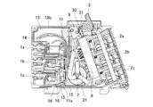
以下、本発明を具体化した実施の形態を、図面に基づいて詳細に説明する。図1〜図6は、本発明に係る回路遮断器の一例を示し、図1(a)は負荷側端子方向から見た正面図、図1(b)はA−A線断面図、図2は左ケースを外した状態の左側面図、図3は図2の状態の斜視図であり、何れも出力オフ状態の場合を示している。また、図4〜図6は出力オン状態の場合を示し、図4はA−A線断面図、図5は左ケースを外した状態の左側面図、図6は図5の状態の斜視図である。 DESCRIPTION OF EXEMPLARY EMBODIMENTS Hereinafter, embodiments of the invention will be described in detail with reference to the drawings. 1 to 6 show an example of a circuit breaker according to the present invention. FIG. 1 (a) is a front view seen from the load side terminal direction, FIG. 1 (b) is a cross-sectional view taken along line AA, FIG. Is a left side view with the left case removed, and FIG. 3 is a perspective view of the state of FIG. 2, both showing the output off state. 4 to 6 show a case where the output is on, FIG. 4 is a cross-sectional view taken along line AA, FIG. 5 is a left side view with the left case removed, and FIG. 6 is a perspective view of the state of FIG. It is.
各図において、1(1a,1b,2c)は電源側端子、2(2a,2b,2c)は負荷側端子であり、電源側端子1及び負荷側端子2は、縦に一直線上に整列配置された3端子を有し、単相3線式電路に設置する回路遮断器を示している。また、3は電源側端子1から負荷側端子2に至る電路をオン/オフ操作する操作ハンドル、5は開閉接点部4の一方を構成する固定接点、6は他方を構成する可動接点、7は漏電を検出するための零相変流器、8は開閉接点部4を開動作させるためのセパレータ、9はラッチ機構を備えて漏電や過電流等の電路異常が発生した場合にセパレータ8を開動作させる開閉機構部、11は開閉機構部9を操作して遮断動作させる引き外し板、13は漏電が発生したらトリップコイル14を動作させるための回路を組み付けたプリント基板、15は過電流を検知するバイメタル片、16は短絡を検知する可動電磁片である。
In each figure, 1 (1a, 1b, 2c) is a power supply side terminal, 2 (2a, 2b, 2c) is a load side terminal, and the power
尚、遮断器ケース18は、左ケース18aと、この左ケース18aとほぼ対称に形成された右ケース18bとで構成されている。また、図1において中央の負荷側端子2bは閉塞部材19により閉塞されているが、使用しない端子はこのように施蓋される。
The
セパレータ8は、筒状に形成されて負荷側端子2を設けた前面に平行に設置され、個々の負荷側端子2a〜2cから延設された固定接点5を収容するよう配置されている。そして、この固定接点5に合わせて3つの可動接点6が内部に組み付けられている。こうして、セパレータ8に開閉接点部4が配置され、セパレータ8をその長手方向(略上下方向)にスライドすることで固定接点5と可動接点6とが接触/解離動作する。即ち、開閉接点部4が開閉動作する。
また、このセパレータ8は、遮断器ケース18との間に配置されたコイルバネ21により、常時上方に付勢されている。
The
The
開閉機構部9は、このように形成されたセパレータ8の上部に連続形成されている。セパレータ8の上部には開閉機構部9の枠体23が連続形成され、その中に第1回動片22aと第2回動片22bから成るラッチ機構22が形成されている。第1回動片22aには、引き外し板11の上端が係合する係合突起25、第2係合片22bに係止する係止突起26が設けられ、第2回動片22bには、第1回動片22aが係止する係止段部27、後述するリンク30に係止する係止突起28が設けられている。
The opening /
そして、操作ハンドル3とセパレータ8とは、コ字状金具から成るリンク(連携部材)30を介して連結されている。このリンク30は、一端が操作ハンドル3に軸支され、他端がセパレータ8の上端に係合すると共に、第2回動片22bの係止突起28に係止するよう配置されている。また、操作ハンドル3のリンク30軸支部の近傍には、軸支したリンク30の所定角度以上の回動を阻止して、抜けを防止するための規制突起31が形成されている。
And the
このように形成された回路遮断器は、以下のように動作する。まず、図1〜図3に示すオフ状態では、セパレータ8はコイルバネ21により付勢されて上方にスライドした状態にあり、開閉接点部4は開状態となっている。即ち、負荷側端子2は電源側端子1から開放された状態にある。また、開閉機構部9は、ラッチ状態(第1回動片22aが第2回動片22bに係止して第2回動片の所定方向の回動が阻止された状態)にある。
この状態から操作ハンドル3を後方に回動すると、図4〜図6に示すように操作ハンドル3に連結されたリンク30により押圧されてセパレータ8がその長手方向の軸に沿って下方にスライドする。また、セパレータ8に一体化されている開閉機構部9もラッチ状態を維持したまま移動する。
The circuit breaker thus formed operates as follows. First, in the OFF state shown in FIGS. 1 to 3, the
When the
こうして操作ハンドル3の回動を最終位置(レバーが水平になる位置)まで続けると、固定接点5に可動接点6が接触して開閉接点部4は閉状態(オン状態)となり、負荷側端子2と電源側端子1の間の電路は接続される。そして、このときコイルバネ21により上方へ付勢されたセパレータ8の押圧力とラッチ状態にある開閉機構部9により、リンク30が上方に押圧されるが、操作ハンドル3先端は遮断器ケース18上面に係止し、それより先に回動することはないので、このオン状態はオフ操作或いはトリップ動作しない限り保持される。
If the rotation of the
この状態で、過電流が電路に流れて例えばバイメタル片15が熱変形すると、引き外し板11のバイメタル片15近傍に設けた係合片11aにバイメタル片15の先端が当接して引き外し板11を上方へスライドさせる。このスライドにより、引き外し板11の上端が開閉機構部9の第1回動片22aに係合して第1回動片22aが回動する。その結果、第1回動片22aと第2回動片22bとの係止が解かれ、ラッチ状態が解除される。このラッチ解除により、セパレータ8の押圧作用を受けているリンク30は回動し、セパレータ8は上方へスライドする。こうして開閉接点部4は、開動作、即ち遮断動作する。
In this state, when an overcurrent flows through the electric circuit and the
また、電路に短絡電流が流れた場合は、短絡電流を受けて可動電磁片16が動作し、引き外し板11を上方にスライドさせる。その後の動作は、バイメタル片15の場合と同様に開閉機構部9のラッチが解除され、セパレータ8がスライドして開閉接点部4が開動作する。
When a short circuit current flows in the electric circuit, the movable
更に、漏電が発生した場合は、零相変流器7がそれを検出してトリップコイル14のプランジャ14aが引き込み動作する。このトリップコイル14の動作により引き外し板11は上方へスライドする。その後の動作は、バイメタル片15や可動電磁片16の場合と同様に、開閉接点部4が開動作する。
こうして、トリップ動作した開閉機構部9は、操作ハンドル3をオフの位置に戻すリセット操作により図1に示す初期状態に戻る。
Further, when a leakage occurs, the zero-phase
Thus, the opening /
このように、開閉機構部はセパレータと共に移動するので、専用の案内手段を設ける必要がなくなる。そのため、開閉機構部は上述したように2つの回動部材を組み合わせただけの構成にでき、構造を簡素化して開閉機構部の小型化を進めることができる。
また、セパレータの上端が操作ハンドルの近くに配置されるので、操作ハンドルの回動操作をセパレータ及び開閉機構部に伝達し易く、開閉機構部を省スペースで作製できる。
更に、操作ハンドルの操作でセパレータ及び開閉機構部を動作させる連携部材は、一端を操作ハンドルに軸支した例えばコ字状金具で良く、簡易な構成で操作ハンドルとセパレータ及び開閉機構部を連結できる。また、連携部材は所定角度以上に回動することがなく、単に操作ハンドルに軸支しただけでもセパレータ及び開閉機構部との係合が外れたり軸支部が外れることがない。
Thus, since the opening / closing mechanism moves together with the separator, there is no need to provide dedicated guide means. Therefore, as described above, the opening / closing mechanism portion can be configured by simply combining two rotating members, and the structure can be simplified and the opening / closing mechanism portion can be reduced in size.
In addition, since the upper end of the separator is disposed near the operation handle, the rotation operation of the operation handle can be easily transmitted to the separator and the opening / closing mechanism, and the opening / closing mechanism can be manufactured in a small space.
Further, the cooperation member that operates the separator and the opening / closing mechanism by operating the operation handle may be, for example, a U-shaped bracket having one end pivotally supported by the operation handle, and the operation handle, the separator, and the opening / closing mechanism can be connected with a simple configuration. . Further, the cooperation member does not rotate more than a predetermined angle, and even if it is simply pivotally supported by the operation handle, the engagement with the separator and the opening / closing mechanism is not released or the pivotal support is not removed.
尚、上記実施形態では、漏電遮断機構を備えた回路遮断器を説明したが、上記セパレータ8、開閉機構部9の構成及び配置は、漏電遮断機能のない過電流遮断機構のみ備えた回路遮断器に対しても容易に適用できる。
In the above-described embodiment, the circuit breaker provided with the leakage breaker mechanism has been described. However, the configuration and arrangement of the
1・・電源側端子、2・・負荷側端子、3・・操作ハンドル、4・・開閉接点部、5・・固定接点、6・・可動接点、7・・零相変流器(異常検知手段)、8・・セパレータ、9・・開閉機構部、15・・バイメタル片(異常検知手段)、16・・可動電磁片(異常検知手段、22・・ラッチ機構、30・・リンク(連携部材)、31・・規制突起。
1 .... Power
Claims (4)
前記開閉機構部は、前記セパレータから連続形成された枠体の中に配置した2つの回動片から成る前記ラッチ機構を有し、前記開閉機構部と前記セパレータとは一体で移動することを特徴とする回路遮断器。 Opening / closing contact part consisting of a fixed contact and a movable contact provided in the electric circuit between the power supply side terminal and the load side terminal, an abnormality detecting means for detecting electric circuit abnormality such as leakage or overcurrent, and opening the switching contact part A circuit breaker comprising: a separator for causing the circuit to open; and an opening / closing mechanism for releasing the latch when an electric circuit abnormality occurs and forcibly moving the separator in a predetermined direction to open the switching contact In the vessel
The opening / closing mechanism section includes the latch mechanism including two rotating pieces arranged in a frame continuously formed from the separator, and the opening / closing mechanism section and the separator move integrally. A circuit breaker.
セパレータは、前記負荷側端子の列に平行に配置して上端を前記操作ハンドル近傍に位置させると共に、適宜部位に個々の可動接点を係止する係止部を縦に備え、開閉機構部を前記セパレータの上部に配置した請求項1記載の回路遮断器。 An operation handle for opening and closing the switching contact portion is arranged on the top surface of the circuit breaker case, and a plurality of power supply side terminals are arranged on the back surface, and a plurality of load side terminals are arranged in the vertical direction on the front surface, respectively.
The separator is arranged in parallel with the row of the load side terminals and has an upper end positioned in the vicinity of the operation handle, and vertically provided with a locking portion for locking each movable contact at an appropriate position, and the opening / closing mechanism portion is The circuit breaker according to claim 1, wherein the circuit breaker is disposed on an upper portion of the separator.
Priority Applications (3)
| Application Number | Priority Date | Filing Date | Title |
|---|---|---|---|
| JP2006268693A JP4933208B2 (en) | 2006-09-29 | 2006-09-29 | Circuit breaker |
| KR1020070098156A KR101045465B1 (en) | 2006-09-29 | 2007-09-28 | Circuit breaker |
| CN2007101532922A CN101154539B (en) | 2006-09-29 | 2007-09-29 | Circuit breaker |
Applications Claiming Priority (1)
| Application Number | Priority Date | Filing Date | Title |
|---|---|---|---|
| JP2006268693A JP4933208B2 (en) | 2006-09-29 | 2006-09-29 | Circuit breaker |
Publications (2)
| Publication Number | Publication Date |
|---|---|
| JP2008091111A JP2008091111A (en) | 2008-04-17 |
| JP4933208B2 true JP4933208B2 (en) | 2012-05-16 |
Family
ID=39256104
Family Applications (1)
| Application Number | Title | Priority Date | Filing Date |
|---|---|---|---|
| JP2006268693A Active JP4933208B2 (en) | 2006-09-29 | 2006-09-29 | Circuit breaker |
Country Status (2)
| Country | Link |
|---|---|
| JP (1) | JP4933208B2 (en) |
| CN (1) | CN101154539B (en) |
Families Citing this family (9)
| Publication number | Priority date | Publication date | Assignee | Title |
|---|---|---|---|---|
| JP4908121B2 (en) * | 2006-09-07 | 2012-04-04 | 河村電器産業株式会社 | Circuit breaker |
| JP4908118B2 (en) * | 2006-09-05 | 2012-04-04 | 河村電器産業株式会社 | Circuit breaker |
| JP4852385B2 (en) * | 2006-10-05 | 2012-01-11 | 河村電器産業株式会社 | Circuit breaker |
| JP4908139B2 (en) * | 2006-10-05 | 2012-04-04 | 河村電器産業株式会社 | Circuit breaker |
| CN102683131B (en) * | 2011-03-09 | 2014-10-08 | 上海电科电器科技有限公司 | Circuit breaker for optimizing space allocation |
| US9589755B1 (en) * | 2016-04-27 | 2017-03-07 | Sensata Technologies, Inc. | Circuit breaker having a framed finger area |
| CN109767958B (en) * | 2019-02-15 | 2019-11-29 | 黄河科技学院 | A kind of electronic breaker |
| JP7302498B2 (en) * | 2020-02-12 | 2023-07-04 | 富士電機機器制御株式会社 | circuit breaker |
| CN112164629B (en) * | 2020-09-25 | 2023-05-12 | 湖南瑞智电气科技有限公司 | Grounding circuit breaker |
Family Cites Families (4)
| Publication number | Priority date | Publication date | Assignee | Title |
|---|---|---|---|---|
| FR2612570A1 (en) * | 1987-03-17 | 1988-09-23 | Alsthom | MECHANICAL ENERGY STORAGE DEVICE HAVING NULL ACCELERATION STRENGTH |
| EP1206783A2 (en) * | 2000-03-03 | 2002-05-22 | General Electric Company | Contact depression stabilizer for 4 pole molded case circuit breaker |
| JP4333060B2 (en) * | 2001-08-06 | 2009-09-16 | 富士電機機器制御株式会社 | Protective switch |
| JP2006032319A (en) * | 2004-06-16 | 2006-02-02 | Kawamura Electric Inc | Circuit breaker |
-
2006
- 2006-09-29 JP JP2006268693A patent/JP4933208B2/en active Active
-
2007
- 2007-09-29 CN CN2007101532922A patent/CN101154539B/en active Active
Also Published As
| Publication number | Publication date |
|---|---|
| JP2008091111A (en) | 2008-04-17 |
| CN101154539A (en) | 2008-04-02 |
| CN101154539B (en) | 2011-11-16 |
Similar Documents
| Publication | Publication Date | Title |
|---|---|---|
| JP4933208B2 (en) | Circuit breaker | |
| US20140048513A1 (en) | Circuit breaker | |
| JP4621751B2 (en) | Circuit breaker | |
| EP3373319B1 (en) | Circuit breaker with instant trip mechanism | |
| WO2015004805A1 (en) | Circuit breaker | |
| JP4769263B2 (en) | Circuit breaker | |
| US10811209B2 (en) | Switching mechanism of circuit breaker | |
| CA2783232C (en) | Electrical switching apparatus and secondary trip mechanism therefor | |
| US10460898B2 (en) | Circuit breakers | |
| KR101789224B1 (en) | Thermal overload relay | |
| JP4960072B2 (en) | Circuit breaker | |
| JP4908139B2 (en) | Circuit breaker | |
| JP2008034146A (en) | Electromagnetic tripper for circuit breaker | |
| JP2003051237A (en) | Protection switch | |
| JP2009212065A (en) | Circuit breaker | |
| JP4908118B2 (en) | Circuit breaker | |
| JP4851295B2 (en) | Circuit breaker | |
| JP4856518B2 (en) | Circuit breaker | |
| JP2007128794A (en) | Circuit breaker | |
| JP2006196242A (en) | Circuit breaker | |
| JP4852385B2 (en) | Circuit breaker | |
| JP4856522B2 (en) | Circuit breaker | |
| JP4994804B2 (en) | Circuit breaker | |
| JP2008123807A (en) | Circuit breaker | |
| JP2008282774A (en) | Circuit breaker |
Legal Events
| Date | Code | Title | Description |
|---|---|---|---|
| A621 | Written request for application examination |
Free format text: JAPANESE INTERMEDIATE CODE: A621 Effective date: 20090818 |
|
| A977 | Report on retrieval |
Free format text: JAPANESE INTERMEDIATE CODE: A971007 Effective date: 20110915 |
|
| A131 | Notification of reasons for refusal |
Free format text: JAPANESE INTERMEDIATE CODE: A131 Effective date: 20110920 |
|
| A521 | Request for written amendment filed |
Free format text: JAPANESE INTERMEDIATE CODE: A523 Effective date: 20111118 |
|
| TRDD | Decision of grant or rejection written | ||
| A01 | Written decision to grant a patent or to grant a registration (utility model) |
Free format text: JAPANESE INTERMEDIATE CODE: A01 Effective date: 20120117 |
|
| A01 | Written decision to grant a patent or to grant a registration (utility model) |
Free format text: JAPANESE INTERMEDIATE CODE: A01 |
|
| A61 | First payment of annual fees (during grant procedure) |
Free format text: JAPANESE INTERMEDIATE CODE: A61 Effective date: 20120216 |
|
| R150 | Certificate of patent or registration of utility model |
Ref document number: 4933208 Country of ref document: JP Free format text: JAPANESE INTERMEDIATE CODE: R150 Free format text: JAPANESE INTERMEDIATE CODE: R150 |
|
| FPAY | Renewal fee payment (event date is renewal date of database) |
Free format text: PAYMENT UNTIL: 20150224 Year of fee payment: 3 |
|
| R250 | Receipt of annual fees |
Free format text: JAPANESE INTERMEDIATE CODE: R250 |
|
| R250 | Receipt of annual fees |
Free format text: JAPANESE INTERMEDIATE CODE: R250 |
|
| R250 | Receipt of annual fees |
Free format text: JAPANESE INTERMEDIATE CODE: R250 |
|
| R250 | Receipt of annual fees |
Free format text: JAPANESE INTERMEDIATE CODE: R250 |
|
| R250 | Receipt of annual fees |
Free format text: JAPANESE INTERMEDIATE CODE: R250 |
|
| R250 | Receipt of annual fees |
Free format text: JAPANESE INTERMEDIATE CODE: R250 |