EP0282714B1 - Ceramic tipped pivot rod and method for its manufacture - Google Patents
Ceramic tipped pivot rod and method for its manufacture Download PDFInfo
- Publication number
- EP0282714B1 EP0282714B1 EP88101507A EP88101507A EP0282714B1 EP 0282714 B1 EP0282714 B1 EP 0282714B1 EP 88101507 A EP88101507 A EP 88101507A EP 88101507 A EP88101507 A EP 88101507A EP 0282714 B1 EP0282714 B1 EP 0282714B1
- Authority
- EP
- European Patent Office
- Prior art keywords
- pivot
- insert
- mounting shaft
- peripheral wall
- pivot insert
- Prior art date
- Legal status (The legal status is an assumption and is not a legal conclusion. Google has not performed a legal analysis and makes no representation as to the accuracy of the status listed.)
- Expired - Lifetime
Links
Images


Classifications
-
- F—MECHANICAL ENGINEERING; LIGHTING; HEATING; WEAPONS; BLASTING
- F01—MACHINES OR ENGINES IN GENERAL; ENGINE PLANTS IN GENERAL; STEAM ENGINES
- F01L—CYCLICALLY OPERATING VALVES FOR MACHINES OR ENGINES
- F01L1/00—Valve-gear or valve arrangements, e.g. lift-valve gear
- F01L1/12—Transmitting gear between valve drive and valve
- F01L1/14—Tappets; Push rods
- F01L1/146—Push-rods
-
- F—MECHANICAL ENGINEERING; LIGHTING; HEATING; WEAPONS; BLASTING
- F02—COMBUSTION ENGINES; HOT-GAS OR COMBUSTION-PRODUCT ENGINE PLANTS
- F02M—SUPPLYING COMBUSTION ENGINES IN GENERAL WITH COMBUSTIBLE MIXTURES OR CONSTITUENTS THEREOF
- F02M57/00—Fuel-injectors combined or associated with other devices
- F02M57/02—Injectors structurally combined with fuel-injection pumps
- F02M57/022—Injectors structurally combined with fuel-injection pumps characterised by the pump drive
- F02M57/023—Injectors structurally combined with fuel-injection pumps characterised by the pump drive mechanical
-
- F—MECHANICAL ENGINEERING; LIGHTING; HEATING; WEAPONS; BLASTING
- F02—COMBUSTION ENGINES; HOT-GAS OR COMBUSTION-PRODUCT ENGINE PLANTS
- F02M—SUPPLYING COMBUSTION ENGINES IN GENERAL WITH COMBUSTIBLE MIXTURES OR CONSTITUENTS THEREOF
- F02M59/00—Pumps specially adapted for fuel-injection and not provided for in groups F02M39/00 -F02M57/00, e.g. rotary cylinder-block type of pumps
- F02M59/44—Details, components parts, or accessories not provided for in, or of interest apart from, the apparatus of groups F02M59/02 - F02M59/42; Pumps having transducers, e.g. to measure displacement of pump rack or piston
- F02M59/445—Selection of particular materials
-
- Y—GENERAL TAGGING OF NEW TECHNOLOGICAL DEVELOPMENTS; GENERAL TAGGING OF CROSS-SECTIONAL TECHNOLOGIES SPANNING OVER SEVERAL SECTIONS OF THE IPC; TECHNICAL SUBJECTS COVERED BY FORMER USPC CROSS-REFERENCE ART COLLECTIONS [XRACs] AND DIGESTS
- Y10—TECHNICAL SUBJECTS COVERED BY FORMER USPC
- Y10T—TECHNICAL SUBJECTS COVERED BY FORMER US CLASSIFICATION
- Y10T29/00—Metal working
- Y10T29/49—Method of mechanical manufacture
- Y10T29/49229—Prime mover or fluid pump making
- Y10T29/49295—Push rod or rocker arm making
-
- Y—GENERAL TAGGING OF NEW TECHNOLOGICAL DEVELOPMENTS; GENERAL TAGGING OF CROSS-SECTIONAL TECHNOLOGIES SPANNING OVER SEVERAL SECTIONS OF THE IPC; TECHNICAL SUBJECTS COVERED BY FORMER USPC CROSS-REFERENCE ART COLLECTIONS [XRACs] AND DIGESTS
- Y10—TECHNICAL SUBJECTS COVERED BY FORMER USPC
- Y10T—TECHNICAL SUBJECTS COVERED BY FORMER US CLASSIFICATION
- Y10T29/00—Metal working
- Y10T29/49—Method of mechanical manufacture
- Y10T29/49826—Assembling or joining
- Y10T29/49945—Assembling or joining by driven force fit
-
- Y—GENERAL TAGGING OF NEW TECHNOLOGICAL DEVELOPMENTS; GENERAL TAGGING OF CROSS-SECTIONAL TECHNOLOGIES SPANNING OVER SEVERAL SECTIONS OF THE IPC; TECHNICAL SUBJECTS COVERED BY FORMER USPC CROSS-REFERENCE ART COLLECTIONS [XRACs] AND DIGESTS
- Y10—TECHNICAL SUBJECTS COVERED BY FORMER USPC
- Y10T—TECHNICAL SUBJECTS COVERED BY FORMER US CLASSIFICATION
- Y10T403/00—Joints and connections
- Y10T403/21—Utilizing thermal characteristic, e.g., expansion or contraction, etc.
-
- Y—GENERAL TAGGING OF NEW TECHNOLOGICAL DEVELOPMENTS; GENERAL TAGGING OF CROSS-SECTIONAL TECHNOLOGIES SPANNING OVER SEVERAL SECTIONS OF THE IPC; TECHNICAL SUBJECTS COVERED BY FORMER USPC CROSS-REFERENCE ART COLLECTIONS [XRACs] AND DIGESTS
- Y10—TECHNICAL SUBJECTS COVERED BY FORMER USPC
- Y10T—TECHNICAL SUBJECTS COVERED BY FORMER US CLASSIFICATION
- Y10T403/00—Joints and connections
- Y10T403/49—Member deformed in situ
- Y10T403/4966—Deformation occurs simultaneously with assembly
-
- Y—GENERAL TAGGING OF NEW TECHNOLOGICAL DEVELOPMENTS; GENERAL TAGGING OF CROSS-SECTIONAL TECHNOLOGIES SPANNING OVER SEVERAL SECTIONS OF THE IPC; TECHNICAL SUBJECTS COVERED BY FORMER USPC CROSS-REFERENCE ART COLLECTIONS [XRACs] AND DIGESTS
- Y10—TECHNICAL SUBJECTS COVERED BY FORMER USPC
- Y10T—TECHNICAL SUBJECTS COVERED BY FORMER US CLASSIFICATION
- Y10T74/00—Machine element or mechanism
- Y10T74/21—Elements
- Y10T74/2142—Pitmans and connecting rods
Definitions
- the present invention relates to pivot rods, such as push rods of the type found included in fuel injector valve drive trains and engine cylinder valve drive trains.
- a pivot rod comprising a mounting shaft having an interior receiving space at at least one end thereof and a pivot insert formed of a ceramic material having a maximum tensile principle stress, said pivot insert being positioned with a first portion thereof disposed within said receiving space and a second portion thereof projecting axially beyond said end of the mounting shaft.
- a pivot rod of this kind is disclosed in the prior art of DE-A 3 239 325.
- the body of the tappet is a cylindrical piece formed, for example, of cast iron, steel, or the like, to which a disc-shaped wear resisting insert of a ceramic material is mounted within a complementary shaped recess in the end of the tapped body.
- US-A 4 508 067 discloses a tappet and a cam contact member therefor wherein a shaft-like solid tapped body made of, for example, cast iron, has an end socket in which a cam contact member made of a brittle, hard ceramic-based material is held by soldering or glueing.
- the contact surface is given a spherical surface having dimensioning that is determined in accordance with a special formula utilizing the maximum contact force expected between the cam contacting surface and cam, the Young's modulus of the material of the cam contacting surface, and the Poissons' ratio of the material of the cam contacting surface.
- the rear surface of the cam contacting member is flat and a concavity is provided between this rear surface and the bottom wall of the socket of the solid tappet body within which it is held so that the flat surface on the cam contact member opposite the cam engaging surface will always deflect toward the cavity during operation for reducing the contact stresses and wear associated therewith.
- a pivot rod such as a push tube of the type used in engine drive trains for operating fuel injectors and cylinder valves
- a ceramic pivot insert may be attached to a mounting shaft by an interference fit securement without exceeding the maximum tensile principle stress of the ceramic material, either during assembly or during use, despite the fact that the insert projects axially beyond the end of the mounting shaft and despite manufacturing tolerances of the mounting shaft and pivot insert.
- mounting shaft prefferably formed from either standard hollow tube stock or from specially manufactured pieces produced by casting or from solid rod stock.
- a further object of the present invention is to enable the ceramic insert, in its projecting portion, to have an abutment surface in abutting engagement upon an end surface of the peripheral wall for limiting the extent to which the insert is inserted into the interior of the mounting shaft, as well as to provide a means, in addition to the interference fit, for facilitating the direct transference of load from the contact surface of the ceramic insert to the mounting shaft.
- Still another object of the present invention is to provide a method of manufacturing a pivot rod which will achieve the above set forth objects.
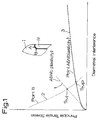
- Figure 1 represents a schematic representation of the principle tensile stresses occurring, with varying amounts of press fit, at two regions, A, B, of high tensile stress, each of which is caused by different aspects of the loading/assembly conditions existing for a pivot rod having a pivot insert I secured within a receiving space of a mounting shaft R, with a portion of the pivot insert I extending axially beyond the end of the mounting shaft R and having a portion with an abutment surface in abutting engagement upon an end surface of a peripheral wall of the shaft R.
- the stresses at point A are the result of assembly forces, i.e., the pressure produced by the press fit, while the stresses at point B are the result of axial load transfer from the insert I to the edge of the mounting shaft R.
- Solid line 3 represents the curve of the assembly stresses occuring at point A when the peripheral wall defining the receiving space of shaft R is caused to plastically deform during the press fit securement of the pivot insert thereto.
- the principle tensile stress approaches some limiting value as the diametral interference is increased without limit.
- the diametral interference can be selected without regard to the maximum stress of the ceramic material used for the pivot insert I.
- FIG. 2 depicts an engine cylinder head valve drive train wherein ball and socket joints 11 are provided at each of opposite ends of the push rod 13 used to transmit movement produced by a cam 15 to a valve rocker lever 17, the lever 17 being used to seat and unseat valves 19 with respect to the valve seat inserts 21 via the cross head 23.
- Figure 3 depicts a fuel injector drive train having four ball and socket joints 25.
- the first pair of joints 25 are disposed at opposite ends of a push rod 27 in a manner similar to that for push rod 13 of the arrangement of Figure 2.
- motion is transmitted from the injector rocker lever 29 to the injector piston 31 through the intermediary of a modified push rod 33 which forms the ball part for a pair of ball and socket joints 25 at each of opposite ends thereof.
- a pivot rod in accordance with the present invention may have two ball pivot inserts 29b (such as for part 33 of Figure 3), two socket parts 29s, or only a single pivot insert 29b, 29s secured to only one end of the mounting shaft 30.
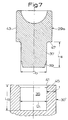
- the mounting shaft is formed of "off the shelf" tubing such as MT 1020, 1021 steel tubing of a standard size, tolerances, and wall thickness as specified in ASTM A-513, while in another embodiment ( Figure 7) the mounting shaft 30′ is formed from a piece of standard rod stock, or may be a cast piece.
- the through hole of the tubing forms an interior receiving space 33 for receiving a first, stem, portion 35 of the pivot insert 29b or 29s
- the receiving space is a recess 35 that is formed into the end portion of mounting shaft 30′ by machining in the case of rod stock and molding in the case of a cast piece.
- the inserting end of stem part 37 is provided with a chamfering 39 and the rim of the receiving space 33, 35 is provided with a chamfering 41.
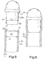
- the thickness t of the peripheral wall circumscribing the receiving space 33 or 35 and the material composition thereof is coordinated to the maximum tensile principle stress (i.e., the maximum tensile stress allowable without causing material failure) of the ceramic material of which the insert part 29b or 29s is formed, so that the peripheral wall will be plastically deformed by the first portion 37 of the pivot insert during formation of the interference fit securement, as reflected, in exaggerated form, in Figure 6.
- the interference fit securement is constructed as a means for preventing the maximum tensile principle stress of the ceramic material from being exceeded, despite variations in the degree of diametral interference existing between the internal diameter D i of the receiving space 33, 35 and the external diameter D o of the stem portion of the pivot insert resulting from manufacturing tolerances of the mounting shaft and pivot insert.
- the pivot inserts 29s and 29b also have a second portion 43 which projects axially beyond the end of the mounting shaft 30, 30′ after securement of the pivot insert to the mounting shaft.
- the end surface 45 of mounting shaft 30′ will not engage the facing surface 47 of the pivot insert. Under such circumstances, it is sufficient that the above-described factors be coordinated.
- the surface 47 will act as an abutment surface which abuttingly engages upon the end surface 45 of the mounting shaft 30, 30′ and thus serves to limit the extent to which the first portion 37 is inserted into the interior receiving space 33, 35 and provides a means, in addition to the frictional effects of the interference fit, by which loading may be transferred from the pivot insert 29b, 29s, to the mounting shaft 30, 30′.
- the axial length of the stem that is in interference fit securement with the peripheral wall of the mounting shaft also be coordinated to the maximum tensile principle stress for the ceramic material of which the pivot insert is formed.
- both the 1,47 mm (0,058 inch) and 1,65 mm (0,065 inch) wall thickness tubings may be considered equally suitable for use in achieving an interference fit securement, in accordance with the present invention, for this example.
- a diametral interference would be aimed for which would be sufficiently to the right of the minimum stress level points shown on the curves of Figure 8 so that, even if the maximum manufacturing tolerance variations occur in terms of a plus tolerancing of the diameter D i and a minus tolerancing of the diameter D O , a diametral interference will not occur that is unsuitably to the left of the minimum stress level points of these curves shown in Figure 8.
- a pivot rod produced in accordance with the foregoing has been found to have a significantly increased wear life, and the method used for its manufacture achieves a significant simplification in the production process and thus renders it less costly. Furthermore, by sizing the wall thickness of the mounting shaft so that it will yield at a pressure such that the induced tensile "hoop" stress in the ceramic is less than the critical (failure) value, the possibility of tensile failure of the ceramic pivot insert can be avoided, not only during use, but also under the high stress loading occurring during the press fit assembly operation.
- the present invention finds particular utility in cylinder head valve and fuel injector drive train components for engines, such as diesel engines, but will also find utility in any environment where it is necessary or desirable to use a ceramic ball and/or socket component due to the high compressive stresses to which the part will be subjected and/or where the value of a dramatically increased wear-free life outweighs the costs associated with using ceramic materials that are more expensive than the metals which are conventionally utilized.
Landscapes
- Engineering & Computer Science (AREA)
- Mechanical Engineering (AREA)
- General Engineering & Computer Science (AREA)
- Chemical & Material Sciences (AREA)
- Combustion & Propulsion (AREA)
- Valve-Gear Or Valve Arrangements (AREA)
- Fuel-Injection Apparatus (AREA)
- Pivots And Pivotal Connections (AREA)
Description
- The present invention relates to pivot rods, such as push rods of the type found included in fuel injector valve drive trains and engine cylinder valve drive trains. In particular the present invention relates to a pivot rod comprising a mounting shaft having an interior receiving space at at least one end thereof and a pivot insert formed of a ceramic material having a maximum tensile principle stress, said pivot insert being positioned with a first portion thereof disposed within said receiving space and a second portion thereof projecting axially beyond said end of the mounting shaft.
- A pivot rod of this kind is disclosed in the prior art of DE-A 3 239 325. In this prior art the body of the tappet is a cylindrical piece formed, for example, of cast iron, steel, or the like, to which a disc-shaped wear resisting insert of a ceramic material is mounted within a complementary shaped recess in the end of the tapped body. By making the ceramic wear resisting insert of a disc shape with a specific outer contact surface, and having this wear resisting insert fully received within the end recess of the tappet body, hoop stress problems are avoided, there being no tensile stress loading of the ceramic insert (tensile loading being the "Achilles heel" of ceramic material, which are highly resistant to compressive loading). However, such a design has the disadvantage that it precludes the use of simple tube stock as a mounting shaft for a pivot insert, requiring instead a body member having a conforming recess with a bottom wall, which must be produced by the casting or machining. Moreover, the design of this prior art is of limited applicability, since it cannot be used for attaching a wear resisting plug or insert in a manner which will result in the plug or insert being subjected to tensile hoop stresses, not merely compressive hoop stresses, e.g., where the insert projects axially beyond the end of the mounting shaft. A similar construction with an insert mounted within the recess by way of an interference or press fit is disclosed in US-A 4 366 785.
- As the use of ceramic components can produce a dramatic reduction in wear to such an extent that, even with a metal socket-ceramic ball combination, a life of as much as 800.000 km (500.000 miles) can be expected before unacceptably large wear will have resulted (i.e., an increase of as much as 20 times the life of prior art metal-to-metal ball and socket joints as known e.g. from US-A 3 272 190. Thus, a definite advantage can be achieved if the pivot insert plugs for push rods and the like are made of a wear resisting ceramic material. On the other hand, a difficult problem exists in the design of ceramic tipped push rods concerning the attachment of the ceramic (i.e., silicon nitride, silicon carbide, zirconia, etc.) to the end of the tube.
- When joining a metal plug to a metal tube, a "press fit" has normally been used as the means for attaching the plug inserts to the tube since that is the simplest and most economical method of attaching such parts. However, the problem that arises when doing this with ceramic end pieces is that the press fit induces a tensile "hoop" stress in the ceramic part which is directly proportional to the amount of "press" used to hold the ceramic end pieces. In metals, this is usually no great problem because of the ductility of the metal, but which ceramics too much tensile stress leads to possible fracturing of the ceramic piece. This fracture problem is compounded by the uncertainty in the "failure" criteria for such ceramic materials. While the amount of "press" can be controlled directly by strict tolerancing of the parts involved, this has been tried with the result that the "required" tolerances were not only uneconomically small, but were also unproducible with today's technology.
- US-A 4 508 067 discloses a tappet and a cam contact member therefor wherein a shaft-like solid tapped body made of, for example, cast iron, has an end socket in which a cam contact member made of a brittle, hard ceramic-based material is held by soldering or glueing. In order to reduce high-Hertz (contact) stresses, the contact surface is given a spherical surface having dimensioning that is determined in accordance with a special formula utilizing the maximum contact force expected between the cam contacting surface and cam, the Young's modulus of the material of the cam contacting surface, and the Poissons' ratio of the material of the cam contacting surface. Furthermore, the rear surface of the cam contacting member is flat and a concavity is provided between this rear surface and the bottom wall of the socket of the solid tappet body within which it is held so that the flat surface on the cam contact member opposite the cam engaging surface will always deflect toward the cavity during operation for reducing the contact stresses and wear associated therewith. However, numerous deficiencies exist in such a design. Firstly, it is hard to obtain a sufficient bond between a ceramic insert and a metallic body member by soldering or glueing. Furthermore, when soldering is used, adverse temperature effects are possible. Also, the precision machining associated with producing this type of contact member renders it considerably more expensive than a typical press fit mount, while the bending stresses associated with a design wherein a ceramic piece is "always" deflecting on contact could cause damage to the ceramic insert which is formed of an essentially brittle material.
- In view of the foregoing, it is an object of the present invention to provide a pivot rod, such as a push tube of the type used in engine drive trains for operating fuel injectors and cylinder valves, wherein a ceramic pivot insert may be attached to a mounting shaft by an interference fit securement without exceeding the maximum tensile principle stress of the ceramic material, either during assembly or during use, despite the fact that the insert projects axially beyond the end of the mounting shaft and despite manufacturing tolerances of the mounting shaft and pivot insert. This is achieved in accordance with the invention by the features of claims 1 and 8.
- It is a further object of the present invention to enable the mounting shaft to be formed from either standard hollow tube stock or from specially manufactured pieces produced by casting or from solid rod stock.
- It is yet another object of the present invention to enable the ceramic insert to be provided with either convexly shaped or concavely shaped contact surfaces.
- A further object of the present invention is to enable the ceramic insert, in its projecting portion, to have an abutment surface in abutting engagement upon an end surface of the peripheral wall for limiting the extent to which the insert is inserted into the interior of the mounting shaft, as well as to provide a means, in addition to the interference fit, for facilitating the direct transference of load from the contact surface of the ceramic insert to the mounting shaft.
- Still another object of the present invention is to provide a method of manufacturing a pivot rod which will achieve the above set forth objects.
- It is a specific object of the present invention to provide a method of manufacturing a pivot rod with a pivot insert of a ceramic material wherein the thickness and material composition of a peripheral wall of the mounting shaft that circumscribes a receiving space for the ceramic pivot insert is coordinated to the maximum tensile principle stress of the ceramic material so that the peripheral wall will plastically deform under a stress below the maximum tensile principle stress of the ceramic material, whereby securement of the pivot insert to the peripheral wall of the mounting shaft by an interference fit will not exceed the maximum tensile principle stress of the ceramic material, despite variations in the degree of diametral interference existing between the peripheral wall and insert part, due to plastic deformation of the peripheral wall during formation of the interference fit.
- These and other objects in accordance with the present invention are achieved, in accordance with preferred embodiments of the present invention which take advantage of relationships between principle tensile stress and diametral interference that have been determined during development of this invention and which are explainable with reference to Figure 1. Figure 1 represents a schematic representation of the principle tensile stresses occurring, with varying amounts of press fit, at two regions, A, B, of high tensile stress, each of which is caused by different aspects of the loading/assembly conditions existing for a pivot rod having a pivot insert I secured within a receiving space of a mounting shaft R, with a portion of the pivot insert I extending axially beyond the end of the mounting shaft R and having a portion with an abutment surface in abutting engagement upon an end surface of a peripheral wall of the shaft R. The stresses at point A are the result of assembly forces, i.e., the pressure produced by the press fit, while the stresses at point B are the result of axial load transfer from the insert I to the edge of the mounting shaft R.
- As can be seen from Figure 1, when a press fit securement of insert I to shaft R is produced without plastic deformation, as represented by dotted line 1, the stresses at point A increase as the amount of diametral interference is increased. On the other hand, as can be seen from dotted line 2, the stresses at point B decrease dramatically with increasing diametral interference. This is a result of the fact that curve 2 represents the effect of the diametral interference upon the force transfer between the insert I and the mounting shaft R, which, at large interferences, occurs mostly via friction along the press fit interface; while, at small interferences, there is less frictional load transfer and more force is transferred from the insert I to the mounting shaft R at the abutment interface at the end of the shaft R. Thus, an optimum diametral interference value occurs at the circled point SM where curves 1 and 2 intersect. However, for a ceramic material such as silicon nitride, the interference required to prevent exceeding of its tensile stress limit is uneconomically small, i.e., the cost of precision machining a material like silicon nitride, that is very hard to machine with sufficiently small tolerances, is too high.
-
Solid line 3 represents the curve of the assembly stresses occuring at point A when the peripheral wall defining the receiving space of shaft R is caused to plastically deform during the press fit securement of the pivot insert thereto. As can be seen fromcurve 3, the principle tensile stress approaches some limiting value as the diametral interference is increased without limit. As a result, it has been found that, if the plasticity effects are incorporated into the design, the diametral interference can be selected without regard to the maximum stress of the ceramic material used for the pivot insert I. - For example, with reference to Figure 1, it can be seen that the X-ed point of intersection SMP, representing the optimum stress level achievable based upon the curves for the stresses at point A with plasticity and point B (which is the same with or without plastic deformation of the mounting shaft during assembly), is considerably lower than optimum stress SM obtained without plasticity and it is achieved a larger diametral interference. Moreover, it can be seen that, even with doubling of the diametral interference, a principle tensile strength level will be achieved that is well below the optimum value sm. Thus, precision machining of the difficult to machine ceramic part can be eliminated by choosing a value of diametral interference that is sufficiently greater than that for point SMP so that, even with easily obtainable manufacturing tolerances, the maximum tensile principle stress of the ceramic material will not be exceeded.
- These and other characteristics, features and benefits of the present invention will become more apparent from the following detailed description and accompanying drawings.
-
- Figure 1 is a schematic representation of principle tensile stress in a ceramic pivot insert with varying amounts of press fit;
- Figures 2 and 3 are schematic representations, respectively, of a cylinder head valve and fuel injector drive train incorporating a pivot rod in accordance with the present invention;
- Figure 4 is a perspective view of a pivot rod in accordance with an embodiment of the present invention for use in either of the Figure 2 or Figure 3 drive trains;
- Figures 5 and 6 are views of a pivot rod using a hollow tubular mounting shaft just prior to and after mounting of the pivot insert, respectively, the mounting shaft being shown in cross-section;
- Figure 7 is a cross-sectional view of a pivot rod in accordance with the present invention, just prior to assembly, wherein the mounting shaft has a socket formed into its end; and
- Figure 8 is a schematic representation of maximum tensile principle stress curves illustrating the effect of wall thickness and the axial length of the interference fit.
- It has been found that in a drive train of the type schematically indicated in either Figure 2 or Figure 3, by way of example, ceramic ball and socket joints can increase the compressive loads to which such joints may be subjected and, even when only one of the ball and socket parts is formed of a ceramic material, the life of the joint achievable before an unacceptably large amount of wear occurs in lubricating oil of degraded quality can be increased by over an order of magnitude. In this regard, it is noted that Figure 2 depicts an engine cylinder head valve drive train wherein ball and
socket joints 11 are provided at each of opposite ends of thepush rod 13 used to transmit movement produced by acam 15 to avalve rocker lever 17, thelever 17 being used to seat andunseat valves 19 with respect to thevalve seat inserts 21 via thecross head 23. - Figure 3, on the other hand, depicts a fuel injector drive train having four ball and
socket joints 25. The first pair ofjoints 25 are disposed at opposite ends of apush rod 27 in a manner similar to that forpush rod 13 of the arrangement of Figure 2. On the other hand, motion is transmitted from the injector rocker lever 29 to theinjector piston 31 through the intermediary of a modifiedpush rod 33 which forms the ball part for a pair of ball andsocket joints 25 at each of opposite ends thereof. - It is noted that, while the present invention finds particular utility in drive trains of the type shown in Figures 2 and 3 (wherein high loads are experienced, servicing of the ball and socket joints is costly and time consuming, and the required frequency of servicing can be an important factor in the purchase of an engine for a vehicle or piece of equipment of which it is a part), the inventive pivot rod will also find utility in numerous other environments which have similar requirements. Furthermore, while the
push rods socket insert 29s which are secured to opposite ends of amounting shaft 30, it should be appreciated that, depending upon the application, a pivot rod in accordance with the present invention may have twoball pivot inserts 29b (such as forpart 33 of Figure 3), twosocket parts 29s, or only a single pivot insert 29b, 29s secured to only one end of themounting shaft 30. - In accordance with one embodiment (that of Figures 5 and 6), the mounting shaft is formed of "off the shelf" tubing such as MT 1020, 1021 steel tubing of a standard size, tolerances, and wall thickness as specified in ASTM A-513, while in another embodiment (Figure 7) the
mounting shaft 30′ is formed from a piece of standard rod stock, or may be a cast piece. In the former case, the through hole of the tubing forms an interior receivingspace 33 for receiving a first, stem,portion 35 of the pivot insert 29b or 29s, while in the latter case the receiving space is arecess 35 that is formed into the end portion ofmounting shaft 30′ by machining in the case of rod stock and molding in the case of a cast piece. - To facilitate the press fit interconnection of the
stem part 37 within thereceiving space stem part 37 is provided with achamfering 39 and the rim of thereceiving space chamfering 41. Furthermore, in accordance with the present invention, the thickness t of the peripheral wall circumscribing thereceiving space insert part first portion 37 of the pivot insert during formation of the interference fit securement, as reflected, in exaggerated form, in Figure 6. In this manner, as described above in detail with reference to Figure 1, the interference fit securement is constructed as a means for preventing the maximum tensile principle stress of the ceramic material from being exceeded, despite variations in the degree of diametral interference existing between the internal diameter Di of thereceiving space - As can also be seen from the drawings, the pivot inserts 29s and 29b also have a
second portion 43 which projects axially beyond the end of the mountingshaft stem portion 37 is greater than the length LR of the wall surrounding the receivingspace 35, theend surface 45 of mountingshaft 30′ will not engage the facingsurface 47 of the pivot insert. Under such circumstances, it is sufficient that the above-described factors be coordinated. - On the other hand, in the case of the Figure 5, 6 embodiment or the embodiment of Figure 7, wherein the length LS is less than the length LR, the
surface 47 will act as an abutment surface which abuttingly engages upon theend surface 45 of the mountingshaft first portion 37 is inserted into theinterior receiving space pivot insert shaft - In order to provide a more specific illustration as to how the interference fit concepts of the present invention may be applied in a specific case, reference will now be made to Figure 8. In Figure 8, maximum principle stress curves have been calculated for a variety of different "off the shelf"
tubes 31 to which a siliconnitride pivot insert - As can be seen form a comparison of the curves for the 2,4 mm (0,095 inch) wall thickness tubing, if a value of 3900 kp/cm² (25.000 ksi) + or _800 kp/cm² (5.000 ksi), is utilized for the maximum allowable tensile stress value of the silicon nitride pivot insert, decreasing the length of the stem that is interference fit has the effect of raising the minimum stress. This occurs because less of the loading is borne by the interference fit and more loading is transferred between the abuttingly engaged
surfaces - Comparing now the three curves for interference fit securements having a stem length of 9,2 mm (0,3622 inch), it can be seen that reducing the wall thickness from 2,4 mm (0,095 inch) to 1,65 mm (0,065 inch) produces curves having approximately the same minimum stress level, but the thinner 1,65 mm (0,065 inch), tube achieves this minimum at a greater diametral interference value and for diametral interferences greater than that at which the minimum stress level point is produced, the stress levels remain significantly lower than those for the case where the 2,4 mm (0,095 inch) wall thickness tubing is used.
- On the other hand, when the curve for the 1,65 mm (0,065 inch) wall thickness tubing is compared with that of the 1,47 mm (0,058 inch) wall thickness tubing, it can be seen that, once again, the change has resulted in an increase of the diametral interference necessary to produce the minimum stress level without there being a significant change in the minimum stress level. However, unlike the situation relative to the 2,4 mm (0,095 inch) wall thickness tubing, no dramatic decrease in stress levels occurs between the curves for the 1,65 mm (0,065 inch) and 1,47 mm (0,058 inch) wall thickness tubings in the curve portions representing diametral interferences that are larger than that at which the minimum stress level is achieved and all such values are within the 3900 kp/cm² (25.000 ksi) + or _800 kp/cm² (5.000 ksi) allowable maximum stress values for the silicon nitride pivot insert. Since small interferences are more costly and difficult to produce than large diametral interferences, from a practical standpoint both the 1,47 mm (0,058 inch) and 1,65 mm (0,065 inch) wall thickness tubings may be considered equally suitable for use in achieving an interference fit securement, in accordance with the present invention, for this example. It is also pointed out that a diametral interference would be aimed for which would be sufficiently to the right of the minimum stress level points shown on the curves of Figure 8 so that, even if the maximum manufacturing tolerance variations occur in terms of a plus tolerancing of the diameter Di and a minus tolerancing of the diameter DO, a diametral interference will not occur that is unsuitably to the left of the minimum stress level points of these curves shown in Figure 8.
- A pivot rod produced in accordance with the foregoing has been found to have a significantly increased wear life, and the method used for its manufacture achieves a significant simplification in the production process and thus renders it less costly. Furthermore, by sizing the wall thickness of the mounting shaft so that it will yield at a pressure such that the induced tensile "hoop" stress in the ceramic is less than the critical (failure) value, the possibility of tensile failure of the ceramic pivot insert can be avoided, not only during use, but also under the high stress loading occurring during the press fit assembly operation.
- The present invention finds particular utility in cylinder head valve and fuel injector drive train components for engines, such as diesel engines, but will also find utility in any environment where it is necessary or desirable to use a ceramic ball and/or socket component due to the high compressive stresses to which the part will be subjected and/or where the value of a dramatically increased wear-free life outweighs the costs associated with using ceramic materials that are more expensive than the metals which are conventionally utilized.
Claims (9)
said pivot insert being positioned with a first portion thereof disposed within said receiving space and a second portion thereof projecting axially beyond said end of the mounting shaft;
characterized by
characterized by the steps of
Applications Claiming Priority (2)
| Application Number | Priority Date | Filing Date | Title |
|---|---|---|---|
| US22229 | 1987-03-05 | ||
| US07/022,229 US4794894A (en) | 1987-03-05 | 1987-03-05 | Ceramic tipped pivot rod and method for its manufacture |
Publications (2)
| Publication Number | Publication Date |
|---|---|
| EP0282714A1 EP0282714A1 (en) | 1988-09-21 |
| EP0282714B1 true EP0282714B1 (en) | 1991-04-10 |
Family
ID=21808519
Family Applications (1)
| Application Number | Title | Priority Date | Filing Date |
|---|---|---|---|
| EP88101507A Expired - Lifetime EP0282714B1 (en) | 1987-03-05 | 1988-02-03 | Ceramic tipped pivot rod and method for its manufacture |
Country Status (4)
| Country | Link |
|---|---|
| US (1) | US4794894A (en) |
| EP (1) | EP0282714B1 (en) |
| JP (1) | JP2670070B2 (en) |
| DE (1) | DE3862327D1 (en) |
Families Citing this family (27)
| Publication number | Priority date | Publication date | Assignee | Title |
|---|---|---|---|---|
| JPS63289306A (en) * | 1987-05-22 | 1988-11-25 | 日本特殊陶業株式会社 | Manufacture of sliding part |
| US4848286A (en) * | 1988-09-28 | 1989-07-18 | Cummins Engine Company, Inc. | Ceramic tiped pivot rod and method for its manufacture |
| US4966108A (en) * | 1989-04-28 | 1990-10-30 | Cummins Engine Company, Inc. | Sintered ceramic ball and socket joint assembly |
| US5185923A (en) * | 1989-06-16 | 1993-02-16 | Ngk Spark Plug Co., Ltd. | Method of making a frictionally sliding component |
| US5168259A (en) * | 1989-09-19 | 1992-12-01 | Semiconductor Energy Laboratory Co., Ltd. | Superconducting coil |
| US5022313A (en) * | 1990-01-08 | 1991-06-11 | General Motors Corporation | Composite piston assembly for automotive air conditioning compressor |
| US5101779A (en) * | 1991-01-15 | 1992-04-07 | Cummins Engine Company, Inc. | Ceramic link |
| EP0543650B1 (en) * | 1991-11-20 | 1997-04-09 | Canon Kabushiki Kaisha | Cylindrical member and electrophotographic apparatus employing the same |
| US5279211A (en) * | 1992-04-24 | 1994-01-18 | Cummins Engine Company, Inc. | Mechanically retained wear-resistant ceramic pad |
| US5185915A (en) * | 1992-04-27 | 1993-02-16 | General Motors Corporation | Pneumatic booster output rod adjustment method |
| JP2999636B2 (en) * | 1992-09-21 | 2000-01-17 | キヤノン株式会社 | Image forming device |
| DE4237682A1 (en) * | 1992-11-07 | 1994-05-11 | Bosch Gmbh Robert | Fuel injection device, in particular rump nozzle for internal combustion engines |
| US5409165A (en) * | 1993-03-19 | 1995-04-25 | Cummins Engine Company, Inc. | Wear resistant fuel injector plunger assembly |
| US5372100A (en) * | 1993-06-04 | 1994-12-13 | Bertelson; Peter C. | Engine valve train pushrod |
| US5410995A (en) * | 1994-04-15 | 1995-05-02 | Cummins Engine Company, Inc. | Valve crosshead assembly with wear-reducing contact pad |
| US5899383A (en) * | 1994-05-18 | 1999-05-04 | Cummins Engine Company, Inc. | Ceramic fuel injector timing plunger |
| US5774971A (en) * | 1996-12-31 | 1998-07-07 | Manetta; Peter J. | Method of manufacturing standardized pin-based parts |
| US5890413A (en) * | 1997-01-08 | 1999-04-06 | Generac Portable Products, Llc | Piston for water pump and related method |
| US5996226A (en) * | 1997-12-23 | 1999-12-07 | Itt Manufacturing Enterprises, Inc. | Method of manufacturing push rod balls |
| JP2003139261A (en) * | 2001-08-23 | 2003-05-14 | Denso Corp | Electromagnetic valve device and method of manufacturing electromagnetic valve device |
| US8312612B2 (en) * | 2002-04-11 | 2012-11-20 | Blue Sky Vision Partners, Llc | Refurbished punch tip and method for manufacture and refurbishing |
| US7033156B2 (en) * | 2002-04-11 | 2006-04-25 | Luka Gakovic | Ceramic center pin for compaction tooling and method for making same |
| DE102007034032A1 (en) * | 2007-07-20 | 2009-01-22 | Robert Bosch Gmbh | Method and device for producing a high-pressure-tight connection and associated valve cartridge for a solenoid valve |
| JP5298660B2 (en) * | 2008-06-24 | 2013-09-25 | パナソニック株式会社 | refrigerator |
| GB201014059D0 (en) * | 2010-08-24 | 2010-10-06 | Element Six Production Pty Ltd | Wear part |
| JP5637259B2 (en) * | 2013-05-28 | 2014-12-10 | パナソニック株式会社 | refrigerator |
| DE102016219046A1 (en) * | 2016-09-30 | 2018-04-05 | Robert Bosch Gmbh | Plunger assembly for a radial piston pump, radial piston pump |
Family Cites Families (16)
| Publication number | Priority date | Publication date | Assignee | Title |
|---|---|---|---|---|
| GB824808A (en) * | 1957-07-05 | 1959-12-02 | Rolls Royce | Improvements in push rods of internal-combustion engine valve gear |
| US2897805A (en) * | 1957-11-08 | 1959-08-04 | Bundy Tubing Co | Tubular push rod and method of making same |
| US3272190A (en) * | 1965-07-21 | 1966-09-13 | Jr Vincent J Di Matteo | Tapered push rod |
| DE1811712B1 (en) * | 1968-11-29 | 1970-07-30 | Kloeckner Humboldt Deutz Ag | Cam drive, especially for internal combustion engines |
| SU742612A1 (en) * | 1978-04-03 | 1980-06-25 | Производственное Объединение "Автодизель" | Pusher rod |
| JPS56107904U (en) * | 1980-01-21 | 1981-08-21 | ||
| JPS5713203A (en) * | 1980-06-30 | 1982-01-23 | Isuzu Motors Ltd | Push rod |
| JPS5713204A (en) * | 1980-06-30 | 1982-01-23 | Isuzu Motors Ltd | Push rod |
| US4366785A (en) * | 1980-09-19 | 1983-01-04 | Caterpillar Tractor Co. | Tappet with wear resisting insert |
| US4453505A (en) * | 1982-06-11 | 1984-06-12 | Standard Oil Company (Indiana) | Composite push rod and process |
| DE3239325A1 (en) * | 1982-10-23 | 1984-04-26 | Feldmühle AG, 4000 Düsseldorf | Valve tappet for an internal combustion engine |
| DE3308550A1 (en) * | 1983-03-10 | 1984-09-13 | M.A.N. Maschinenfabrik Augsburg-Nürnberg AG, 8500 Nürnberg | FLAT TOWEL FOR VALVE ACTUATORS |
| JPS6050204A (en) * | 1983-08-31 | 1985-03-19 | Ngk Insulators Ltd | Metal-ceramics bonded body and its manufacturing process |
| JPS60103082A (en) * | 1983-11-09 | 1985-06-07 | 日本碍子株式会社 | Metal ceramic bonded body and manufacture |
| JPS61286501A (en) * | 1985-06-12 | 1986-12-17 | Ngk Insulators Ltd | Turbine rotor and its manufacture |
| JPS624528A (en) * | 1985-06-12 | 1987-01-10 | Ngk Insulators Ltd | Ceramics-metal combined structure |
-
1987
- 1987-03-05 US US07/022,229 patent/US4794894A/en not_active Expired - Lifetime
-
1988
- 1988-02-03 EP EP88101507A patent/EP0282714B1/en not_active Expired - Lifetime
- 1988-02-03 DE DE8888101507T patent/DE3862327D1/en not_active Expired - Lifetime
- 1988-03-04 JP JP63051430A patent/JP2670070B2/en not_active Expired - Lifetime
Also Published As
| Publication number | Publication date |
|---|---|
| EP0282714A1 (en) | 1988-09-21 |
| JPS63280901A (en) | 1988-11-17 |
| JP2670070B2 (en) | 1997-10-29 |
| US4794894A (en) | 1989-01-03 |
| DE3862327D1 (en) | 1991-05-16 |
Similar Documents
| Publication | Publication Date | Title |
|---|---|---|
| US4794894A (en) | Ceramic tipped pivot rod and method for its manufacture | |
| US4848286A (en) | Ceramic tiped pivot rod and method for its manufacture | |
| EP0142334B1 (en) | A metal-ceramic composite body and a method of manufacturing the same | |
| US5279211A (en) | Mechanically retained wear-resistant ceramic pad | |
| US4806040A (en) | Ceramic ball and socket joint | |
| JPH0520182B2 (en) | ||
| US5168841A (en) | Tappet with ceramic seat plate | |
| JPS61172643A (en) | Manufacture of integral piston for internal combustion engine | |
| US4850095A (en) | Method of forming crowned sliding surface in mechanical part | |
| US5826331A (en) | Method for the production of a fracture split connection component | |
| US5076149A (en) | Wrist pin, piston assembly and method for making same | |
| US4966108A (en) | Sintered ceramic ball and socket joint assembly | |
| EP0682171A2 (en) | Valve crosshead assembly with wear-reducing contact pad | |
| US20040250652A1 (en) | Fractured powder metal connecting rod and a method of manufacturing the same | |
| US5809842A (en) | Ceramic sliding component | |
| US5327814A (en) | Mechanical assemblies and methods of making same | |
| JP3396261B2 (en) | Method of manufacturing camshaft for internal combustion engine | |
| EP0711904B1 (en) | Sliding part and a method of producing thereof | |
| US5572963A (en) | Hydraulic tappet | |
| JP3331527B2 (en) | Tappet for internal combustion engine and method for manufacturing the same | |
| KR970007388B1 (en) | Camshaft | |
| EP0773853B1 (en) | Method of making connecting rod | |
| JPH1162517A (en) | Sliding parts for internal combustion engines | |
| JPH0459485B2 (en) |
Legal Events
| Date | Code | Title | Description |
|---|---|---|---|
| PUAI | Public reference made under article 153(3) epc to a published international application that has entered the european phase |
Free format text: ORIGINAL CODE: 0009012 |
|
| AK | Designated contracting states |
Kind code of ref document: A1 Designated state(s): DE GB |
|
| 17P | Request for examination filed |
Effective date: 19880830 |
|
| 17Q | First examination report despatched |
Effective date: 19900201 |
|
| GRAA | (expected) grant |
Free format text: ORIGINAL CODE: 0009210 |
|
| AK | Designated contracting states |
Kind code of ref document: B1 Designated state(s): DE GB |
|
| REF | Corresponds to: |
Ref document number: 3862327 Country of ref document: DE Date of ref document: 19910516 |
|
| PLBE | No opposition filed within time limit |
Free format text: ORIGINAL CODE: 0009261 |
|
| STAA | Information on the status of an ep patent application or granted ep patent |
Free format text: STATUS: NO OPPOSITION FILED WITHIN TIME LIMIT |
|
| 26N | No opposition filed | ||
| PGFP | Annual fee paid to national office [announced via postgrant information from national office to epo] |
Ref country code: DE Payment date: 19960119 Year of fee payment: 9 |
|
| PGFP | Annual fee paid to national office [announced via postgrant information from national office to epo] |
Ref country code: GB Payment date: 19960129 Year of fee payment: 9 |
|
| PG25 | Lapsed in a contracting state [announced via postgrant information from national office to epo] |
Ref country code: GB Effective date: 19970203 |
|
| GBPC | Gb: european patent ceased through non-payment of renewal fee |
Effective date: 19970203 |
|
| PG25 | Lapsed in a contracting state [announced via postgrant information from national office to epo] |
Ref country code: DE Effective date: 19971101 |