EP0282136A2 - Klemmvorrichtung - Google Patents
Klemmvorrichtung Download PDFInfo
- Publication number
- EP0282136A2 EP0282136A2 EP88200419A EP88200419A EP0282136A2 EP 0282136 A2 EP0282136 A2 EP 0282136A2 EP 88200419 A EP88200419 A EP 88200419A EP 88200419 A EP88200419 A EP 88200419A EP 0282136 A2 EP0282136 A2 EP 0282136A2
- Authority
- EP
- European Patent Office
- Prior art keywords
- gripper
- abutment member
- abutment
- grippers
- rod
- Prior art date
- Legal status (The legal status is an assumption and is not a legal conclusion. Google has not performed a legal analysis and makes no representation as to the accuracy of the status listed.)
- Withdrawn
Links
Images
Classifications
-
- H—ELECTRICITY
- H05—ELECTRIC TECHNIQUES NOT OTHERWISE PROVIDED FOR
- H05K—PRINTED CIRCUITS; CASINGS OR CONSTRUCTIONAL DETAILS OF ELECTRIC APPARATUS; MANUFACTURE OF ASSEMBLAGES OF ELECTRICAL COMPONENTS
- H05K3/00—Apparatus or processes for manufacturing printed circuits
- H05K3/30—Assembling printed circuits with electric components, e.g. with resistors
-
- B—PERFORMING OPERATIONS; TRANSPORTING
- B25—HAND TOOLS; PORTABLE POWER-DRIVEN TOOLS; MANIPULATORS
- B25J—MANIPULATORS; CHAMBERS PROVIDED WITH MANIPULATION DEVICES
- B25J15/00—Gripping heads and other end effectors
- B25J15/02—Gripping heads and other end effectors servo-actuated
- B25J15/0253—Gripping heads and other end effectors servo-actuated comprising parallel grippers
-
- H—ELECTRICITY
- H05—ELECTRIC TECHNIQUES NOT OTHERWISE PROVIDED FOR
- H05K—PRINTED CIRCUITS; CASINGS OR CONSTRUCTIONAL DETAILS OF ELECTRIC APPARATUS; MANUFACTURE OF ASSEMBLAGES OF ELECTRICAL COMPONENTS
- H05K13/00—Apparatus or processes specially adapted for manufacturing or adjusting assemblages of electric components
- H05K13/04—Mounting of components, e.g. of leadless components
- H05K13/0404—Pick-and-place heads or apparatus, e.g. with jaws
- H05K13/0408—Incorporating a pick-up tool
-
- Y—GENERAL TAGGING OF NEW TECHNOLOGICAL DEVELOPMENTS; GENERAL TAGGING OF CROSS-SECTIONAL TECHNOLOGIES SPANNING OVER SEVERAL SECTIONS OF THE IPC; TECHNICAL SUBJECTS COVERED BY FORMER USPC CROSS-REFERENCE ART COLLECTIONS [XRACs] AND DIGESTS
- Y10—TECHNICAL SUBJECTS COVERED BY FORMER USPC
- Y10T—TECHNICAL SUBJECTS COVERED BY FORMER US CLASSIFICATION
- Y10T29/00—Metal working
- Y10T29/53—Means to assemble or disassemble
- Y10T29/5313—Means to assemble electrical device
- Y10T29/53174—Means to fasten electrical component to wiring board, base, or substrate
- Y10T29/53178—Chip component
-
- Y—GENERAL TAGGING OF NEW TECHNOLOGICAL DEVELOPMENTS; GENERAL TAGGING OF CROSS-SECTIONAL TECHNOLOGIES SPANNING OVER SEVERAL SECTIONS OF THE IPC; TECHNICAL SUBJECTS COVERED BY FORMER USPC CROSS-REFERENCE ART COLLECTIONS [XRACs] AND DIGESTS
- Y10—TECHNICAL SUBJECTS COVERED BY FORMER USPC
- Y10T—TECHNICAL SUBJECTS COVERED BY FORMER US CLASSIFICATION
- Y10T29/00—Metal working
- Y10T29/53—Means to assemble or disassemble
- Y10T29/5313—Means to assemble electrical device
- Y10T29/53174—Means to fasten electrical component to wiring board, base, or substrate
- Y10T29/53183—Multilead component
Definitions
- the invention relates to a gripping device for an apparatus for placing electronic and/or electrical components on a substrate, for example, a printed-circuit board.
- a gripping device comprising a pair of grippers, each of which comprises a gripper jaw and at least one of which is movable relative to the other to close and open the jaws for gripping and releasing a component.
- the movable gripper, or the grippers if both are movable may be moved by fluid-pressure operated means or by electrically operated means.
- the invention is primarily intended for use in an apparatus which is designed to handle electronic and/or electrical components of different widths, the width of a component being understood herein to be the distance between the two opposite sides of the component which are engaged by the gripper jaws. If only one gripping device, or a series of identical gripping devices, is provided in such an apparatus, obviously the jaws of the device, or each device, must be capable of being opened sufficiently to accept the widest component. With known gripping devices, in order to allow room for the jaws to open to release a component after placing it on the substrate, the spacing between adjacent components on the substrate must be at least equal to the distance between the open jaws plus the thickness of the two jaws.
- one method of overcoming the above limitation is to programme these means so that the gripper jaws are opened to different distances to suit the varying widths of the components to be placed on a given substrate.
- This is an expensive method, however, and the object of the invention is to provide a cheaper and simpler alternative which can be employed in a gripping device in which either fluid-pressure operated means or electrically operated means are provided for moving the movable gripper, or the grippers if both are movable.
- a gripper device comprising a pair of grippers, each of which comprises a gripper jaw and at least one of which is movable relative to the other to close and open the jaws for gripping and releasing a component, is characterised by a stroke-limiting device which is arranged for abutment with a first gripper of said pair of grippers after an initial relative movement between the grippers in the direction to open the jaws so as to limit said initial relative movement between the grippers in this direction, the stroke-limiting device comprising an abutment member which is capable of limited movement relative to said first gripper in the directions of relative movement between the grippers and which has an abutment surface for cooperation with an abutment surface on the first gripper to limit said relative movement of the abutment member in one direction, means being provided for urging the abutment member in the opposite direction to a position in which the abutment surfaces are spaced from one another, and means being provided for locking the abutment member to the second gripper of said pair of grippers against
- the initial relative movement between the grippers requires very little space but is sufficient to release a component held between the gripper jaws.
- the gripping device is raised to bring the jaws to a higher level where they can be fully opened.
- the maximum distance to which the jaws can be opened, and therefore the maximum width of component that the gripping device can handle is not limited by the spacing of the components on the substrate. This freedom is achieved with a simple stroke-limiting device which adds little to the overall cost of the gripping device.
- the abutment member can be of very simple construction.
- it comprises a rod having a first portion which is slidably supported in the first gripper for axial movement relative thereto in the directions of relative movement between the grippers, and a second portion on which the locking means are arranged to act, the abutment member having at one end of the first portion of the rod an annular abutment surface for cooperation with the abutment surface on the first gripper to limit said relative movement of the abutment member in said one direction, and a spring being arranged to act between opposed surfaces on the abutment member and the first gripper to urge the rod axially in the opposite direction to a position in which said abutment surfaces are spaced from one another.
- the abutment member may have a second annular abutment surface for cooperation with a second abutment surface on the first gripper to limit said relative movement of the abutment member in said opposite direction.
- a second spring may be arranged to act between opposed surfaces on the abutment member and the first gripper to exert an axial force on the rod in opposition to that exerted by the first spring such that in the free condition of the abutment member both abutment surfaces on the abutment member are spaced from the abutment surfaces on the first gripper.
- the locking means comprise clamping members which are movably mounted in the second gripper on diametrically opposite sides of said second portion of the rod of the abutment member and which are operable by fluid pressure to clamp the rod between them to lock the abutment member to the second gripper.
- fluid-pressure operated means are used for actuating the movable gripper (or the two grippers if both are movable) the supply of compressed air or vacuum or hydraulic pressure for these means can conveniently provide the fluid pressure for operating the clamping members. This merely requires the provision of fluid ducts in the gripper in which the clamping members are mounted, together with a control valve and means for supplying a signal to actuate the valve.
- the locking means comprise a uni-directional brake device which is mounted on the second gripper for engagement with said second portion of the rod of the abutment member and which is movable between an operative position in which it acts on the rod to lock the abutment member to the second gripper against movement relative thereto in said one direction but permit movement of the abutment relative to the second gripper in the opposite direction, and an inoperative position in which the abutment member is free to move relative to the second gripper in both directions, the brake device being movable between said positions by an overcentre spring device which is actuated by the first gripper, the arrangement being such that at the end of relative movement between the grippers to open the jaws fully the spring device is actuated to move the brake device to the operative position, and at the end of relative movement between the grippers to close the jaws completely when there is no component between them the spring device is actuated to move the brake device to the inoperative position.
- This form of locking means may also
- the brake device may comprise an arm pivotally connected at one end to the second gripper for movement between said operative and inoperative positions and having an aperture through which said second portion of the rod of the abutment member passes, the walls of said aperture being so shaped that in the operative position of the arm a force exerted on the abutment member to move it in said one direction relative to the second gripper causes the rod to become jammed or wedged between the walls of the aperture while the rod is free to slide between said walls in the opposite direction, and in the inoperative position of the arm the rod is free to slide between said walls in both of said directions, and the overcentre spring device being connected between the second gripper and the end of the arm remote from the pivotal connection of the arm to the second gripper.
- the overcentre spring device may comprise a blade spring which is connected at one end to the second gripper and at the other end to the end of said arm remote from the pivotal connection of the arm to the second gripper, and which is movable between a first stable extreme position, in which the spring is bowed towards the first gripper and urges the arm to the operative position, and a second stable extreme position, in which the spring is bowed away from the first gripper and urges the arm to the inoperative position, the spring being movable between the stable extreme positions through an unstable intermediate position, and the first gripper having two elements rigidly connected to it which are disposed on opposite sides of the blade spring and are so arranged that at the end of relative movement between the grippers to open the jaws fully one of said elements engages the spring and moves it from said second extreme position past the intermediate position so that it springs into the first extreme position, and at the end of relative movement between the grippers to close the jaws completely when there is no component between them the other of said elements engages the spring and moves it from the first extreme
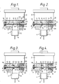
- the gripping device shown in Figures 1 and 2 comprises a pair of grippers 1 and 2 supported in a mounting 3 which is adapted to be fitted in an apparatus for placing electronic and/or electrical components on a substrate, for example, an apparatus similar to that described in the aforementioned European Patent Application No. 0 183 301.
- the grippers 1 and 2 comprise jaws 4 and 5, respectively, which in Figure 1 are shown gripping a component 6. Both grippers may be movably supported in the mounting 3 for translational movement towards and away from one another to close and open the jaws. Alternatively, one gripper may be fixed in the mounting 3 and the other movably supported for movement towards and away from the fixed gripper. For simplicity of description it will be assumed in the present case that the gripper 1 is movable and the gripper 2 fixed.
- the movement of the movable gripper is effected preferably by fluid-pressure operated means, which may be of any convenient known form and therefore need not be illustrated or described in detail.
- fluid-pressure operated means which may be of any convenient known form and therefore need not be illustrated or described in detail.
- These means which are accommodated in the mounting 3, may comprise, for example, a single- or double-acting piston or pistons operated by compressed air or vacuum or by hydraulic pressure.
- each of the grippers 1 and 2 (or the movable gripper if only one is movable) is moved in one direction by compressed air or vacuum or by hydraulic pressure and in the opposite direction by a spring; with a double-acting piston or pistons each gripper (or the movable gripper) is moved in both directions by compressed air or vacuum or by hydraulic pressure.
- the gripper 1 carries an abutment member 7 in the form of a rod 8 with a flanged head 9 at one end and a collar 10 intermediate its ends. Between the head and the collar the rod is slidably supported in a bore 11 in the gripper 1, which bore extends parallel with the directions of movement of the gripper 1.
- the abutment member is thus capable of limited movement relative to the gripper 1 in these directions, the limits of the movement being defined by abutment of the head 9 and collar 10 with the adjacent sides of the gripper 1.
- the head 9 and the collar 10 have annular abutment surfaces 12 and 13, respectively, for cooperation with abutment surfaces 14 and 15, respectively, on the gripper 1.
- a coil spring 16 is held in compression between the flange on the head 9 of the abutment member and the adjacent side of the gripper 1 to urge the abutment member to a position (shown in Figure 1) in which the abutment surfaces 12 an 14 are spaced from one another, which position is determined by the abutment of the surface 13 with the surface 15.
- the rod 8 of the abutment member 7 extends slidably through a bore 17 in the fixed gripper 2.
- two clamping members 18 and 19 are slidably mounted in chambers 20 and 21, respectively, in the gripper 2 for movement towards and away from the rod 8.
- the clamping members 18 and 19 have surfaces 22 and 23, respectively, which bear on two flats on diametrically opposite sides of the rod 8 and which can be clamped on these flats to lock the abutment member 7 to the fixed gripper 2.
- the clamping members 18 and 19 are actuated by compressed air which, under the control of a valve (not shown) in the mounting 3, is admitted through a duct 24 and branch ducts 25 and 26 in the gripper 2 to the spaces in the chambers 20 and 21 on the sides of the clamping members 18 and 19 remote from the rod 8.
- a valve not shown
- the chambers 20 and 21 communicate with atmosphere through a clearance between the rod and the wall of the bore 17.
- the operation of the device is as follows. With the abutment member 7 in the inoperative condition, in which condition the abutment member is urged by the spring 16 to the position shown in Figure 1, and with the gripper jaws 4 and 5 fully open, the device is positioned above a component which is to be picked up and placed on the substrate. At the pick-up position there is always ample room for the gripper jaws to be opened wide enough to accommodate the widest component that the apparatus may be required to handle.
- the gripping device With the abutment member 7 still in the inoperative condition, the gripping device is lowered and the gripper 1 is moved towards the gripper 2 to grip the respective component between the jaws 4 and 5, as shown in Figure 1.
- the component 6 shown in Figure 1 is a comparatively wide component.
- the gripping device is then brought above the position on the substrate where the component is to be placed and the device is lowered to place the component in this position.
- the locking means formed by the clamping members 18 and 19 are actuated to lock the abutment member 7 to the fixed gripper 2.
- gripper 1 carrying the abutment member 7 and the gripper 2 carrying the means for locking the abutment member have been described as movable and fixed grippers, respectively, it will be evident that the gripper 1 could be fixed and the gripper 2 movable.
- the clamping members 18 and 19 may be arranged to be actuated by vacuum or hydraulic pressure instead of compressed air. This would merely entail the connection of the clamping members by rods or the like to vacuum-operated or hydraulically operated pistons movable in cylinders in the gripper 2, springs being provided, if necessary, to urge the pistons in the directions to release the clamping members. Alternatively, if both compressed air and vacuum are supplied to the mounting 3 for the operation of the movable gripper 1, the pistons could be moved in one direction by compressed air and in the other direction by vacuum.
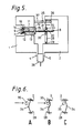
- the locking means for the abutment member 7 in Figure 5 comprise a uni-directional brake device which operates on the same principle as a free-wheel brake and which consists of an arm 28 pivotally mounted at one end on the gripper 2 and formed with an aperture through which passes the portion of the rod 8 of the abutment member 7 which extends from the collar 10 on the side thereof remote from the head 9 of the abutment member.
- the aperture in the arm has two wall portions 30 and 31, respectively, which are disposed on opposite sides of and extend in directions substantially perpendicular to a plane containing both the longitudinal centre-line of the arm 28 and the pivotal axis of the mounting 29 and which, in a direction parallel with the longitudinal centre-line of the arm, are separated by a distance substantially equal to, but not greater than, the distance between said opposite sides of the rod 8.
- the remaining portions 32 and 33 of the walls of the aperture in the arm 28 on said opposite sides of the rod 8 are separated by a distance, measured parallel with the longitudinal centre-line of the arm 28, which is significantly greater than the distance between said sides of the rod 8.
- the arm 28 At its end remote from the pivotal mounting 29 (the upper end as viewed in Figure 5) the arm 28 is acted upon by a blade spring 34 which is connected at one end to the arm 28 and at the other end to the upper part of the gripper 2.
- the spring has an overcentre action, being movable between two stable extreme positions through an unstable intermediate position. The extreme positions are shown in Figures 6A and 6C and the intermediate position in Figure 6B.
- the spring 34 is bowed towards the movable gripper 1 and urges the arm 28 about the pivotal axis of the mounting 29 to an operative position in which a force exerted on the abutment member 7 to move it in the direction of the opening movement of the gripper 1, i.e., to the left in Figure 5, will cause the rod 8 to become jammed or wedged between the wall portions 30 and 31 of the aperture in the arm 28 so that the abutment member is locked by the arm to the fixed gripper 2 against movement relative to this gripper in said direction.
- the change-over of the spring 34 from one extreme position to the other is brought about by means of two protrusions in the form of collars 35 and 36 on a rod 37 which extends from the movable gripper 1 towards the fixed gripper 2, parallel with the rod 8 of the abutment member 7. Between the two collars 35 and 36, which are spaced from one another axially of the rod 37, this rod passes freely through an aperture in the spring 34, which aperture has a size such that the collars 35 and 36 cannot pass through it.
- the gripper 1 is moved away from the gripper 2, i.e., in the direction to open the jaws 4 and 5, until the other collar 36 engages the spring 34 and moves it back past the intermediate position so that it springs into the stable position shown in Figure 6A.
- the jaws 4 and 5 are now fully open and the brake formed by the arm 28 is operative.
- the gripper 1 is moved to close the jaws 4 and 5 on a component, for example, the component 38 in Figure 5, the abutment member 7 can move with the gripper 1 even though the brake is operative since, as already indicated, there is no restraint on the movement of the rod 8 of the abutment member the aperture in the arm 27 in the closing direction.
- the locking means shown in Figures 5 and 6 can also be used to advantage when the movement of the movable gripper, or the grippers if both are movable, is effected by electrically operated means instead of fluid-pressure operated means.
Landscapes
- Engineering & Computer Science (AREA)
- Manufacturing & Machinery (AREA)
- Microelectronics & Electronic Packaging (AREA)
- Robotics (AREA)
- Mechanical Engineering (AREA)
- Manipulator (AREA)
- Automatic Assembly (AREA)
- Feeding Of Workpieces (AREA)
- Supply And Installment Of Electrical Components (AREA)
Applications Claiming Priority (2)
| Application Number | Priority Date | Filing Date | Title |
|---|---|---|---|
| GB8705716 | 1987-03-11 | ||
| GB08705716A GB2201940A (en) | 1987-03-11 | 1987-03-11 | Gripping device |
Publications (2)
| Publication Number | Publication Date |
|---|---|
| EP0282136A2 true EP0282136A2 (de) | 1988-09-14 |
| EP0282136A3 EP0282136A3 (de) | 1990-05-16 |
Family
ID=10613733
Family Applications (1)
| Application Number | Title | Priority Date | Filing Date |
|---|---|---|---|
| EP88200419A Withdrawn EP0282136A3 (de) | 1987-03-11 | 1988-03-04 | Klemmvorrichtung |
Country Status (5)
| Country | Link |
|---|---|
| US (1) | US4839961A (de) |
| EP (1) | EP0282136A3 (de) |
| JP (1) | JPS63237826A (de) |
| KR (1) | KR880012131A (de) |
| GB (1) | GB2201940A (de) |
Cited By (1)
| Publication number | Priority date | Publication date | Assignee | Title |
|---|---|---|---|---|
| DE19928318A1 (de) * | 1999-06-16 | 2001-01-04 | Siemens Ag | Greifwerkzeug mit einer Haltevorrichtung für elektronische Bauelemente |
Families Citing this family (17)
| Publication number | Priority date | Publication date | Assignee | Title |
|---|---|---|---|---|
| US4987676A (en) * | 1989-08-23 | 1991-01-29 | Quad Systems Corporation | End effector for a robotic system |
| US5257689A (en) * | 1991-04-10 | 1993-11-02 | Axis Usa, Inc. | Apparatus for substantially simultaneously processing multiple electric motor parts |
| US5253912A (en) * | 1991-04-10 | 1993-10-19 | Axis Usa, Inc. | Gripper apparatus for electric motor components |
| US6240628B1 (en) * | 1997-09-29 | 2001-06-05 | Matsushita Electric Industrial Co., Ltd. | Device for securing a nozzle of a parts installer |
| US6454332B1 (en) * | 1998-12-04 | 2002-09-24 | Applied Materials, Inc. | Apparatus and methods for handling a substrate |
| KR100283432B1 (ko) | 1999-02-06 | 2001-02-15 | 정문술 | 표면실장기용 그립퍼 |
| US6393694B2 (en) * | 1999-04-23 | 2002-05-28 | Koninklijke Philips Electronics N.V. | Gripping device |
| US20040066514A1 (en) * | 2002-10-08 | 2004-04-08 | Kardos Victor J. | Upper compliant tooling |
| US7320455B2 (en) | 2003-10-24 | 2008-01-22 | Newport Corporation | Instrumented platform for vibration-sensitive equipment |
| US8231098B2 (en) | 2004-12-07 | 2012-07-31 | Newport Corporation | Methods and devices for active vibration damping of an optical structure |
| US9628184B2 (en) | 2013-11-05 | 2017-04-18 | Cisco Technology, Inc. | Efficient optical communication device |
| US10239217B2 (en) * | 2016-02-02 | 2019-03-26 | General Atomics | Magnet gripper systems |
| CN111844112A (zh) * | 2019-04-24 | 2020-10-30 | 北京兰友科技有限公司 | 一种适用于土样转运容器的抓取机械手 |
| CN112543557B (zh) * | 2020-10-29 | 2022-11-11 | 大族激光科技产业集团股份有限公司 | 一种异型引脚电容组装装置 |
| CN112677077A (zh) * | 2020-12-16 | 2021-04-20 | 宁波金日机床有限公司 | 一种基于机械制造的零部件用夹持固定装置 |
| CN114043739B (zh) * | 2021-11-22 | 2025-12-16 | 东莞市创捷电子科技有限公司 | 软胶板组装磁铁设备 |
| CN115351811B (zh) * | 2022-10-21 | 2023-04-07 | 江苏秦劳智能科技有限公司 | 一种工业机器人用机械抓取装置 |
Family Cites Families (6)
| Publication number | Priority date | Publication date | Assignee | Title |
|---|---|---|---|---|
| US4141138A (en) * | 1977-05-31 | 1979-02-27 | King Radio Corporation | Tool for inserting and extracting integrated circuits |
| US4583288A (en) * | 1983-07-12 | 1986-04-22 | Westinghouse Electric Corp. | Apparatus for the acquistion and insertion of dual in-line package components |
| JPS60189298A (ja) * | 1984-03-08 | 1985-09-26 | 松下電器産業株式会社 | リ−ド線挾持装置 |
| NL8403513A (nl) * | 1984-11-19 | 1986-06-16 | Philips Nv | Inrichting voor het plaatsen van electronische en/of electrische onderdelen op een substraat. |
| DE3676195D1 (de) * | 1986-04-28 | 1991-01-24 | Ibm | Roboterzusammenbaugeraet mit roboterwerkzeug zum setzen mehrerer komponenten auf einem werkstueck. |
| US4736971A (en) * | 1986-11-14 | 1988-04-12 | Acme Machine Works, Inc. | Billet grab |
-
1987
- 1987-03-11 GB GB08705716A patent/GB2201940A/en not_active Withdrawn
-
1988
- 1988-03-04 EP EP88200419A patent/EP0282136A3/de not_active Withdrawn
- 1988-03-09 KR KR1019880002419A patent/KR880012131A/ko not_active Withdrawn
- 1988-03-10 JP JP63055061A patent/JPS63237826A/ja active Pending
- 1988-09-19 US US07/248,245 patent/US4839961A/en not_active Expired - Fee Related
Cited By (1)
| Publication number | Priority date | Publication date | Assignee | Title |
|---|---|---|---|---|
| DE19928318A1 (de) * | 1999-06-16 | 2001-01-04 | Siemens Ag | Greifwerkzeug mit einer Haltevorrichtung für elektronische Bauelemente |
Also Published As
| Publication number | Publication date |
|---|---|
| GB2201940A (en) | 1988-09-14 |
| EP0282136A3 (de) | 1990-05-16 |
| JPS63237826A (ja) | 1988-10-04 |
| US4839961A (en) | 1989-06-20 |
| GB8705716D0 (en) | 1987-04-15 |
| KR880012131A (ko) | 1988-11-03 |
Similar Documents
| Publication | Publication Date | Title |
|---|---|---|
| US4839961A (en) | Gripping device | |
| US4789292A (en) | End effector for robotic equipment | |
| US4810018A (en) | Gripping device | |
| US8099992B2 (en) | Automatic safety click | |
| EP1355766B1 (de) | Verfahren und vorrichtung zum aufnehmen und abstellen von behältern | |
| US4653794A (en) | Universal adjustable gripper with center push | |
| US5360249A (en) | Multifunctional end effectors | |
| GB2130550A (en) | Robot hand | |
| US20220388183A1 (en) | Gripper device for a robot gripper and method for operating a gripper device | |
| EP0286178B1 (de) | Greifvorrichtung | |
| US5562320A (en) | Gripper head | |
| CA2149040A1 (en) | Slide actuated holding clamp | |
| EP0302475A1 (de) | Robotergreifkopf zum Erfassen von Gegenständen | |
| JP6989626B2 (ja) | ケーブル加工装置 | |
| JPS63236400A (ja) | 把持装置 | |
| EP0205141A2 (de) | Selbstprogrammierter pneumatischer Greifer | |
| US4510686A (en) | Method and apparatus for straightening and aligning leads and testing electrical functioning of components | |
| JPH0378236B2 (de) | ||
| CN214643159U (zh) | 一种载具装置 | |
| US5277411A (en) | Slide actuated holding clamp | |
| EP0286159A2 (de) | Greifvorrichtung | |
| US20040183320A1 (en) | Bi-directional gripping of rectangular devices/components | |
| CA1263129A (en) | End effector for robotic equipment | |
| JPS63221990A (ja) | ロボツト装置の端部作動体 | |
| CN114986420A (zh) | 一种载具装置 |
Legal Events
| Date | Code | Title | Description |
|---|---|---|---|
| PUAI | Public reference made under article 153(3) epc to a published international application that has entered the european phase |
Free format text: ORIGINAL CODE: 0009012 |
|
| AK | Designated contracting states |
Kind code of ref document: A2 Designated state(s): BE CH DE FR GB IT LI NL SE |
|
| PUAL | Search report despatched |
Free format text: ORIGINAL CODE: 0009013 |
|
| AK | Designated contracting states |
Kind code of ref document: A3 Designated state(s): BE CH DE FR GB IT LI NL SE |
|
| 17P | Request for examination filed |
Effective date: 19901114 |
|
| STAA | Information on the status of an ep patent application or granted ep patent |
Free format text: STATUS: THE APPLICATION IS DEEMED TO BE WITHDRAWN |
|
| 18D | Application deemed to be withdrawn |
Effective date: 19911003 |