EP0281635A1 - Valve device - Google Patents
Valve device Download PDFInfo
- Publication number
- EP0281635A1 EP0281635A1 EP87905792A EP87905792A EP0281635A1 EP 0281635 A1 EP0281635 A1 EP 0281635A1 EP 87905792 A EP87905792 A EP 87905792A EP 87905792 A EP87905792 A EP 87905792A EP 0281635 A1 EP0281635 A1 EP 0281635A1
- Authority
- EP
- European Patent Office
- Prior art keywords
- valve
- pilot
- control valve
- hydraulic fluid
- passage
- Prior art date
- Legal status (The legal status is an assumption and is not a legal conclusion. Google has not performed a legal analysis and makes no representation as to the accuracy of the status listed.)
- Granted
Links
Images


Classifications
-
- F—MECHANICAL ENGINEERING; LIGHTING; HEATING; WEAPONS; BLASTING
- F15—FLUID-PRESSURE ACTUATORS; HYDRAULICS OR PNEUMATICS IN GENERAL
- F15B—SYSTEMS ACTING BY MEANS OF FLUIDS IN GENERAL; FLUID-PRESSURE ACTUATORS, e.g. SERVOMOTORS; DETAILS OF FLUID-PRESSURE SYSTEMS, NOT OTHERWISE PROVIDED FOR
- F15B11/00—Servomotor systems without provision for follow-up action; Circuits therefor
- F15B11/08—Servomotor systems without provision for follow-up action; Circuits therefor with only one servomotor
-
- F—MECHANICAL ENGINEERING; LIGHTING; HEATING; WEAPONS; BLASTING
- F15—FLUID-PRESSURE ACTUATORS; HYDRAULICS OR PNEUMATICS IN GENERAL
- F15B—SYSTEMS ACTING BY MEANS OF FLUIDS IN GENERAL; FLUID-PRESSURE ACTUATORS, e.g. SERVOMOTORS; DETAILS OF FLUID-PRESSURE SYSTEMS, NOT OTHERWISE PROVIDED FOR
- F15B13/00—Details of servomotor systems ; Valves for servomotor systems
- F15B13/02—Fluid distribution or supply devices characterised by their adaptation to the control of servomotors
- F15B13/04—Fluid distribution or supply devices characterised by their adaptation to the control of servomotors for use with a single servomotor
- F15B13/042—Fluid distribution or supply devices characterised by their adaptation to the control of servomotors for use with a single servomotor operated by fluid pressure
- F15B13/0422—Fluid distribution or supply devices characterised by their adaptation to the control of servomotors for use with a single servomotor operated by fluid pressure with manually-operated pilot valves, e.g. joysticks
-
- F—MECHANICAL ENGINEERING; LIGHTING; HEATING; WEAPONS; BLASTING
- F16—ENGINEERING ELEMENTS AND UNITS; GENERAL MEASURES FOR PRODUCING AND MAINTAINING EFFECTIVE FUNCTIONING OF MACHINES OR INSTALLATIONS; THERMAL INSULATION IN GENERAL
- F16K—VALVES; TAPS; COCKS; ACTUATING-FLOATS; DEVICES FOR VENTING OR AERATING
- F16K31/00—Actuating devices; Operating means; Releasing devices
- F16K31/12—Actuating devices; Operating means; Releasing devices actuated by fluid
- F16K31/36—Actuating devices; Operating means; Releasing devices actuated by fluid in which fluid from the circuit is constantly supplied to the fluid motor
- F16K31/363—Actuating devices; Operating means; Releasing devices actuated by fluid in which fluid from the circuit is constantly supplied to the fluid motor the fluid acting on a piston
-
- Y—GENERAL TAGGING OF NEW TECHNOLOGICAL DEVELOPMENTS; GENERAL TAGGING OF CROSS-SECTIONAL TECHNOLOGIES SPANNING OVER SEVERAL SECTIONS OF THE IPC; TECHNICAL SUBJECTS COVERED BY FORMER USPC CROSS-REFERENCE ART COLLECTIONS [XRACs] AND DIGESTS
- Y10—TECHNICAL SUBJECTS COVERED BY FORMER USPC
- Y10T—TECHNICAL SUBJECTS COVERED BY FORMER US CLASSIFICATION
- Y10T137/00—Fluid handling
- Y10T137/8593—Systems
- Y10T137/86493—Multi-way valve unit
- Y10T137/86574—Supply and exhaust
- Y10T137/86582—Pilot-actuated
- Y10T137/86606—Common to plural valve motor chambers
Definitions
- the present invention relates to valve apparatuses and, particularly, to a valve apparatus comprising a flow control valve which is connected in pilot lines connecting a pilot valve and a pilot operated directional control valve to each other, for adjusting a switching speed of the pilot operated directional control valve.
- U.S. Patent Application Serial No. 904,119 (which corresponds to EPC Patent Application No. 86112328.9 or Chinese Patent Application No. 86106036) discloses a pilot hydraulic circuit system in which a flow control valve having incorporated therein a restriction and a check valve is connected to pilot lines connecting a pilot valve supplied with a pilot hydraulic fluid of a predetermined pressure set by a relief valve and a pilot operated directional control valve actuated in response to operation of the pilot valve, to permit free flow of the hydraulic fluid from the pilot valve to the directional control valve, but to restrict flow of the hydraulic fluid from the directional control valve to the pilot valve.
- the flow control valve has added thereto a pressure compensating function making differential pressure across the restriction constant, so that the flow control valve is brought to a pressure-compensated flow control valve.
- the diameter of the restriction incorporated in the flow control valve cannot but be made small, because the flow rate of the pilot hydraulic fluid is low.
- the viscosity of the hydraulic fluid increases when the environmental temperature is low, and pressure loss of the hydraulic fluid passing through the restriction is increased so that the hydraulic fluid flows only at a flow rate lower than a set flow rate. That is, the operating characteristic at the low temperature deteriorates. This results in a difference in the switching speed of the directional control valve from season to season, in particular, between the summer season and the winter season, reducing stability of the operations of the hydraulic actuator.
- a valve apparatus in which it comprises at least one flow control valve incorporated in a body block, and the flow control valve is connected in pilot lines connecting a pilot valve supplied with a pilot hydraulic fluid of a predetermined pressure set by a relief valve and a pilot operated directional control valve actuated in response to operation of the pilot valve, to permit free flow of the hydraulic fluid from the pilot valve to the directional control valve, but to restrict flow of the hydraulic fluid from the directional control valve to the pilot valve, wherein the body block is formed therein with a first passage connected to a return line for the relief valve.
- Heat is generated at the relief valve when the pilot hydraulic fluid is relieved, and the relieved pilot hydraulic fluid is returned to a reservoir through the above-mentioned first passage. This causes the heat generated at the relief valve to be transmitted to the body block through the first passage, to keep the flow control valve warm. Accordingly, the viscosity of the hydraulic fluid flowing through the flow control valve is prevented from increasing even when the environmental temperature is low, thereby improving the operating characteristic at the low temperature.
- the reference numeral 1 denotes a valve apparatus according to the invention.
- the valve apparatus 1 is connected between a pilot valve 2 and pilot chambers 4, 5 of a directional control valve 3 actuated in response to operation of the pilot valve 2, through pilot lines 6-9.
- the valve apparatus 1 is also connected, through a supply line 12, to a pilot pump 10 which supplies a pilot hydraulic fluid to the pilot valve 2.
- the valve apparatus 1 is connected to the pilot valve 2 and a reservoir 11 respectively through a supply line 13 and a return line 14,
- the directional control valve 5 is arranged in a main circuit constituted by a main pump 15 and a hydraulic actuator 16. Operation of the directional control valve 5 controls a flow rate and a direction of the hydraulic fluid supplied from the main pump 15 to the hydraulic actuator 16.
- the valve apparatus 1 comprises a body block 20 which has incorporated therein flow control valves 21, 22 and a relief valve 19.
- the body block 20 is also formed with ports 23-29 and internal passages 30, 31.
- the ports 23, 24 are connected respectively to the pilot lines 6, 7.
- the flow control valve 21 are located between passages 32, 33 communicating respectively with the ports 23, 24.
- the ports 25, 26 connected respectively to the pilot lines 8, 9.
- the flow control valve 22 is located between passages 34, 35 communicating respectively with the ports 25, 26.
- the ports 27, 28 are connected respectively to the supply lines 12, 13, and communicate with each other within the body block 20 through the passage 30.
- the relief valve 19 is connected to the passage 30, to set a pressure of the pilot hydraulic fluid supplied to the pilot valve 2.
- the port 29 is connected to the return line 14, and an outlet of the relief valve 19 communicates with the return line 14 through the passage 31 and the port 29.
- the passage 31 extends through the neighborhood of both the flow control valves 21, 22.
- the flow control valve 21 has its structure described in the above-mentioned U.S. Patent Application Serial No. 904,119 (which corresponds to EPC Patent Application No. 86112328.9 or Chinese Patent Application No. 86106036).
- the flow control valve 21 has a spool 36 which is slidably housed across the passages 32, 33.
- pressure chambers 37, 38 are respectively provided, which communicate respectively with the passages 32, 33.
- the spool 36 has a check valve 39 at an outside central portion of the spool, and has a restriction 40 at an inside central portion of the spool.
- the spool 36 is also provided with a pressure compensating control orifice 41 which reduces an opening degree by displacement of the spool 36 occurring in response to a differential pressure generated across the restriction 40, to maintain the flow rate of the hydraulic fluid constant.
- the flow control valve 22 is the same in construction as the flow control valve 21, and the relief valve 19 has a usual construction.
- the pilot hydraulic fluid from the pilot pump 10 is led to a left-hand valve section of the pilot valve 2 through the passage 30 and the port 28 of the valve apparatus 1, and is further led to the pilot chamber 4 of the directional control valve 3 through the port 23, the flow control valve 21 and the port 24 of the valve apparatus 1.
- the hydraulic fluid within the pilot chamber 5 of the directional control valve 3 is led to the flow control valve 22 through the port 26 of the valve apparatus 1.
- the hydraulic fluid is controlled in flow rate at the flow control valve 22.
- the hydraulic fluid further passes through the port 25 and the pilot valve 2 and is returned to the reservoir 11.
- Control of the flow rate at this time is a control in which the flow rate is restricted and is compensated in pressure by the restriction 40 and the control orifice 41.
- the directional control valve 3 is switched to a left-hand position in the figure, while the directional control valve 3 is adjusted in its switching speed.
- the hydraulic fluid from the main pump 15 is supplied to a head side of the hydraulic actuator 16 so that the hydraulic actuator 16 performs its extending operation.
- the pilot hydraulic fluid from the pilot pump 10 is led to a right-hand valve section of the pilot valve 2 through the passage 30 and the port 28 of the valve apparatus 1, and is further led to the pilot chamber 5 of the directional control valve 5 through the port 25, the flow control valve 22 and the port 26 of the valve apparatus 1.
- the hydraulic fluid within the pilot chamber 4 of the directional control valve 5 is led to the flow control valve 21 through the port 24 of the valve apparatus 1.
- the hydraulic fluid is controlled in flow rate at the flow control valve 21.
- the hydraulic fluid further passes through the port 23 and the pilot valve 2 and is returned to the reservoir 11.
- Control of the flow rate at this time is a control in which the flow rate is restricted and is compensated in pressure by the restriction 40 and the control orifice 41.
- the directional control valve 3 is switched to a right-hand position in the figure, while the directional control valve 3 is adjusted in its switching speed.
- the hydraulic fluid from the main pump 15 is supplied to a rod side of the hydraulic actuator 16 so that the actuator 16 performs its retracting operation.
- the flow control valves 21, 22 are under keeping warm condition even when the environmental temperature is low, the viscosity of the hydraulic fluid flowing through these flow control valves 21, 22 can be maintained constant, that is, the viscosity is prevented from increasing.
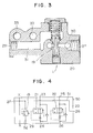
- Fig. 4 shows a valve apparatus 50 according to a modification of the above-described embodiment.
- parts of components similar to those illustrated in Fig. 1 are designated by the same reference numerals.
- the valve apparatus 50 has passages 51, 52 which extend in a fashion different from the above-described first embodiment.
- the passage 52 which transmits heat generated at the relief valve 19 to the body block 20 is arranged in the vicinity of only the flow control valve 21. This embodiment is preferable if it will suffice that keeping warm of, in particular, only the flow control valve 21 is taken into consideration.
- valve apparatuses 60, 61 are connected respectively to the pilot lines 6, 7 and the pilot lines 8, 9.
- the relief valve 19 is arranged on the outside of the valve apparatuses 60, 61 in the usual manner.
- the valve apparatus 60 has a body block 62 in which a flow control valve 63 is incorporated.
- the body block 62 is formed with ports 64-67 and an internal passage 68.
- the ports 64, 65 are connected respectively to the pilot lines 6, 7.
- the flow control valve 63 is located between passages 69, 70 communicating respectively with the ports 64, 65.
- the ports 66, 67 are connected respectively to return lines 71, 72 communicating the outlet of the relief valve 19 with the reservoir 11, and communicate with each other within the body block 20 by the passage 68.
- the passage 68 extends through the neighborhood of the flow control valve 63.
- the body block 62 is also formed therein with a passage 73 which communicates the above-mentioned passage 68 with the passage 69.
- a check valve 74 which prevents flow of the hydraulic fluid from the passage 69 to the passage 68.
- the flow control valve 63 is the same in construction as the flow control valves 21, 22 of the embodiment described previously, and parts or components forming the flow control valve 63 are therefore designated by the same reference numerals as those of the flow control valves 21, 22.
- valve apparatus 61 is similar in construction to the above-mentioned valve apparatus 60. That is, a body block 75 has incorporated therein a flow control valve 76, and is formed with ports 77-80 and passages 81-84. A check valve 85 is provided in the passage 84. However, ports 79, 80 of the passage 80 corresponding to the passage 68 are connected respectively to the return passage 71 and a return passage 86.
- the hydraulic fluid warmed by heat generated at the relief valve 19 keeps warm the body blocks 62, 75 and the flow control valves 63, 76 of the valve apparatuses 60, 61 through the passages 68, 81 and the passages 73, 84.
- the hydraulic fluid also flows through the passages 69, 82 into the pilot lines 6, 8, to thereby perform keeping warm of the body blocks 62, 75 and the flow control valves 63, 76 in a more excellent manner.
- this embodiment like the first embodiment, also improves the operating characteristic of the flow control valves 63, 76 at low temperature, making it possible to secure stability of the operations by the actuator 16.
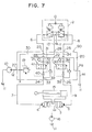
- a valve apparatus 90 of this embodiment is one in which an arrangement corresponding to the passage 73, 84 and the check valves 74, 85 of the embodiment illustrated in Fig. 5 is added to the arrangement of the above-described first embodiment. That is, the body block 20 of the valve apparatus 90 is formed therein with a passage 91 communicating the passage 31 with the passage 32, and a passage 92 communicating the passage 31 with the passage 34. These passages 91, 92 are provided therein respectively with check valves 93, 94 which prevent flow of the hydraulic fluid from the respective passages 32, 34 to the passage 31.
- heat generated at the relief valve 19 is transmitted to the body block 20 also by the hydraulic fluid flowing to the pilot lines 6, 8 through the passages 91, 92 and the passages 32, 34, so that more excellent keeping warm of the flow control valves 21, 22 is achieved.
- the valve apparatus is provided with the pressure-compensated flow control valve or valves described in U.S. Patent Application Serial No. 904,119 (which corresponds to EPC Patent Application No. 86112328.9 or Chinese Patent Application No. 86106036).
- the flow control valve is not limited to this example.
- the flow control valve may be a usual pressure-compensated flow control valve, or may be a flow control valve having no pressure compensating function.
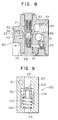
- Fig. 9 shows an embodiment of a valve apparatus having incorporated therein a flow control valve having no pressure compensating function.
- the valve apparatus 100 of this embodiment has two flow control valves 101 incorporated in the body block 20.
- Each of the flow control valves 101 is arranged such that a spool 105 biased toward a closed position by a spring 102 and formed with a restriction 103 and a lateral bore 104 is slidably housed in the body block 20.
- the spool 105 is urged against the spring 102 to open the passage to permit the hydraulic fluid to freely flow through the lateral bore 104 and the port 24.
- this flow 'control valve 101 also permits free flow of the hydraulic fluid from the pilot valve 2 to the directional control valve 3 illustrated in Fig. 1, but restricts flow of the hydraulic fluid from the directional control valve 3 to the pilot valve 2.
- the passage 31 to which the hydraulic fluid flows from the relief valve 19 in accordance with the invention is formed in the vicinity of the flow control valve 101.
- the operating characteristic of the flow control valve at low temperature can be improved as compared with the conventional valve apparatus, and the switching speed of the directional control valve adjusted by the flow control valve can be maintained constant without being influenced by the environmental temperature.
- the switching speed of the directional control valve adjusted by the flow control valve can be maintained constant without being influenced by the environmental temperature.
Abstract
Description
- The present invention relates to valve apparatuses and, particularly, to a valve apparatus comprising a flow control valve which is connected in pilot lines connecting a pilot valve and a pilot operated directional control valve to each other, for adjusting a switching speed of the pilot operated directional control valve.
- U.S. Patent Application Serial No. 904,119 (which corresponds to EPC Patent Application No. 86112328.9 or Chinese Patent Application No. 86106036) discloses a pilot hydraulic circuit system in which a flow control valve having incorporated therein a restriction and a check valve is connected to pilot lines connecting a pilot valve supplied with a pilot hydraulic fluid of a predetermined pressure set by a relief valve and a pilot operated directional control valve actuated in response to operation of the pilot valve, to permit free flow of the hydraulic fluid from the pilot valve to the directional control valve, but to restrict flow of the hydraulic fluid from the directional control valve to the pilot valve. Preferably, the flow control valve has added thereto a pressure compensating function making differential pressure across the restriction constant, so that the flow control valve is brought to a pressure-compensated flow control valve.
- In general, in the pilot hydraulic circuit system, when an operating lever is operated to return the pilot valve from an operating position to a neutral position, a return speed at which the directional control valve is returned to the neutral position is high. Therefore, a rise of a brake pressure generated in a main line becomes also extremely steep, so that large shock occurs on a hydraulic actuator which is controlled by the directional control valve.
- In the pilot hydraulic circuit system disclosed in the above-mentioned patent application, by the action of the flow control valve, the hydraulic fluid flow is abought to free flow when the pilot hydraulic fluid is supplied from the pilot valve to a pilot chamber of the directional control valve, but the check valve and the restriction function when the pilot hydraulic fluid is returned from the pilot chamber of the directional control valve to the pilot valve, to restrict the flow of the hydraulic fluid. Also at this time, the flow rate of the restricted hydraulic fluid is compensated in pressure so that the flow rate is maintained substantially constant. This causes the switching speed of the directional control valve to be adjusted, to thereby eliminate the above-mentioned problem that the shock occurs on the hydraulic actuator.
- By the way, for the flow control valve constructed as described above, the diameter of the restriction incorporated in the flow control valve cannot but be made small, because the flow rate of the pilot hydraulic fluid is low. In case where the diameter of the restriction is small in this way, however, the viscosity of the hydraulic fluid increases when the environmental temperature is low, and pressure loss of the hydraulic fluid passing through the restriction is increased so that the hydraulic fluid flows only at a flow rate lower than a set flow rate. That is, the operating characteristic at the low temperature deteriorates. This results in a difference in the switching speed of the directional control valve from season to season, in particular, between the summer season and the winter season, reducing stability of the operations of the hydraulic actuator.
- It is, therefore, an object of the invention to provide a valve apparatus which can improve an operating characteristic of a flow control valve at a low temperature.
- The above object can be achieved by a valve apparatus in which it comprises at least one flow control valve incorporated in a body block, and the flow control valve is connected in pilot lines connecting a pilot valve supplied with a pilot hydraulic fluid of a predetermined pressure set by a relief valve and a pilot operated directional control valve actuated in response to operation of the pilot valve, to permit free flow of the hydraulic fluid from the pilot valve to the directional control valve, but to restrict flow of the hydraulic fluid from the directional control valve to the pilot valve, wherein the body block is formed therein with a first passage connected to a return line for the relief valve.
- Heat is generated at the relief valve when the pilot hydraulic fluid is relieved, and the relieved pilot hydraulic fluid is returned to a reservoir through the above-mentioned first passage. This causes the heat generated at the relief valve to be transmitted to the body block through the first passage, to keep the flow control valve warm. Accordingly, the viscosity of the hydraulic fluid flowing through the flow control valve is prevented from increasing even when the environmental temperature is low, thereby improving the operating characteristic at the low temperature.
-
- Fig. 1 is a circuit diagram showing a pilot hydraulic circuit system having incorporated therein a valve apparatus according to an embodiment of the invention;
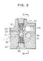
- Fig. 2 is a cross-sectional view showing the structure of the valve apparatus;
- Fig. 3 is a cross-sectional view taken along line III - III in Fig. 2;
- Fig. 4 is a circuit diagram of a valve apparatus according to another embodiment of the invention;
- Fig. 5 is a circuit diagram showing a pilot hydraulic circuit system having incorporated therein a valve apparatus according to still another embodiment of the invention;
- Fig. 6 is a cross-sectional view showing the structure of the valve apparatus;
- Fig. 7 is a circuit diagram showing a pilot hydraulic circuit system having incorporated therein a valve apparatus according to still further embodiment of the invention;
- Fig. 8 is a cross-sectional view showing the structure of the valve apparatus; and
- Fig. 9 is a cross-sectional view showing the structure of a valve apparatus according to still further embodiment of the invention.
- Embodiments of the invention will be described below with reference to Figs. 1 through 9.
- In Fig. 1, the reference numeral 1 denotes a valve apparatus according to the invention. The valve apparatus 1 is connected between a
pilot valve 2 andpilot chambers pilot valve 2, through pilot lines 6-9. The valve apparatus 1 is also connected, through asupply line 12, to apilot pump 10 which supplies a pilot hydraulic fluid to thepilot valve 2. The valve apparatus 1 is connected to thepilot valve 2 and areservoir 11 respectively through asupply line 13 and areturn line 14, - The
directional control valve 5 is arranged in a main circuit constituted by amain pump 15 and ahydraulic actuator 16. Operation of thedirectional control valve 5 controls a flow rate and a direction of the hydraulic fluid supplied from themain pump 15 to thehydraulic actuator 16. - Referring also to Figs. 2 and 3, the valve apparatus 1 comprises a
body block 20 which has incorporated thereinflow control valves relief valve 19. Thebody block 20 is also formed with ports 23-29 andinternal passages ports pilot lines flow control valve 21 are located betweenpassages ports ports pilot lines flow control valve 22 is located betweenpassages ports ports supply lines body block 20 through thepassage 30. Therelief valve 19 is connected to thepassage 30, to set a pressure of the pilot hydraulic fluid supplied to thepilot valve 2. Theport 29 is connected to thereturn line 14, and an outlet of therelief valve 19 communicates with thereturn line 14 through thepassage 31 and theport 29. Thepassage 31 extends through the neighborhood of both theflow control valves - The
flow control valve 21 has its structure described in the above-mentioned U.S. Patent Application Serial No. 904,119 (which corresponds to EPC Patent Application No. 86112328.9 or Chinese Patent Application No. 86106036). Stating briefly, theflow control valve 21 has aspool 36 which is slidably housed across thepassages spool 36,pressure chambers passages spool 36 has acheck valve 39 at an outside central portion of the spool, and has arestriction 40 at an inside central portion of the spool. Thespool 36 is also provided with a pressure compensatingcontrol orifice 41 which reduces an opening degree by displacement of thespool 36 occurring in response to a differential pressure generated across therestriction 40, to maintain the flow rate of the hydraulic fluid constant. - The
flow control valve 22 is the same in construction as theflow control valve 21, and therelief valve 19 has a usual construction. - In the pilot hydraulic circuit system including such valve apparatus 1, when an operating lever of the
pilot valve 2 is laid down, for example, to the left as viewed in Fig. 1, the pilot hydraulic fluid from thepilot pump 10 is led to a left-hand valve section of thepilot valve 2 through thepassage 30 and theport 28 of the valve apparatus 1, and is further led to thepilot chamber 4 of the directional control valve 3 through theport 23, theflow control valve 21 and theport 24 of the valve apparatus 1. On the other hand, the hydraulic fluid within thepilot chamber 5 of the directional control valve 3 is led to theflow control valve 22 through theport 26 of the valve apparatus 1. The hydraulic fluid is controlled in flow rate at theflow control valve 22. The hydraulic fluid further passes through theport 25 and thepilot valve 2 and is returned to thereservoir 11. Control of the flow rate at this time is a control in which the flow rate is restricted and is compensated in pressure by therestriction 40 and thecontrol orifice 41. By this flow of the hydraulic fluid, the directional control valve 3 is switched to a left-hand position in the figure, while the directional control valve 3 is adjusted in its switching speed. Thus, the hydraulic fluid from themain pump 15 is supplied to a head side of thehydraulic actuator 16 so that thehydraulic actuator 16 performs its extending operation. - When the operating lever of the
pilot valve 2 is laid down to the right opposite to the above, the pilot hydraulic fluid from thepilot pump 10 is led to a right-hand valve section of thepilot valve 2 through thepassage 30 and theport 28 of the valve apparatus 1, and is further led to thepilot chamber 5 of thedirectional control valve 5 through theport 25, theflow control valve 22 and theport 26 of the valve apparatus 1. On the other hand, the hydraulic fluid within thepilot chamber 4 of thedirectional control valve 5 is led to theflow control valve 21 through theport 24 of the valve apparatus 1. The hydraulic fluid is controlled in flow rate at theflow control valve 21. The hydraulic fluid further passes through theport 23 and thepilot valve 2 and is returned to thereservoir 11. Control of the flow rate at this time is a control in which the flow rate is restricted and is compensated in pressure by therestriction 40 and thecontrol orifice 41. By this flow of the hydraulic fluid, the directional control valve 3 is switched to a right-hand position in the figure, while the directional control valve 3 is adjusted in its switching speed. Thus, the hydraulic fluid from themain pump 15 is supplied to a rod side of thehydraulic actuator 16 so that theactuator 16 performs its retracting operation. - In such a state that the
pilot valve 2 is retained, for example, at a neutral position, communication between thesupply line 13 and thepilot lines passage 30 within the valve apparatus 1 is closed. Thus, the pilot hydraulic fluid from thepilot pump 10 is led to thepassage 31 through therelief valve 19, and is further led to thereservoir 11 through theport 29 and thereturn line 14. On this occasion, heat generated at therelief valve 19 is transmitted to theentire body block 20 through thepassage 31, so that theflow control valves passage 31 is arranged in the vicinity of theflow control valves relief valve 19 is also incorporated in the valve apparatus 1, relief heat is transmitted also from therelief valve 19 to thebody block 20. Thus, keeping warm of theflow control valves - In the valve apparatus 1 constructed as described above, since the
flow control valves flow control valves hydraulic actuator 16 can be ensured. - Fig. 4 shows a
valve apparatus 50 according to a modification of the above-described embodiment. In the figure, parts of components similar to those illustrated in Fig. 1 are designated by the same reference numerals. - The
valve apparatus 50 haspassages passage 52 which transmits heat generated at therelief valve 19 to thebody block 20 is arranged in the vicinity of only theflow control valve 21. This embodiment is preferable if it will suffice that keeping warm of, in particular, only theflow control valve 21 is taken into consideration. - Another embodiment of the invention will be described with reference to qigs. 5 and 6. In these figures, parts or components similar to those illustrated in Fig. 1 are designated by the same reference numerals.
- In this embodiment,
separate valve apparatuses pilot lines pilot lines relief valve 19 is arranged on the outside of thevalve apparatuses - Referring also to Fig. 6, the
valve apparatus 60 has abody block 62 in which aflow control valve 63 is incorporated. Thebody block 62 is formed with ports 64-67 and aninternal passage 68. Theports pilot lines flow control valve 63 is located betweenpassages ports ports lines relief valve 19 with thereservoir 11, and communicate with each other within thebody block 20 by thepassage 68. Thepassage 68 extends through the neighborhood of theflow control valve 63. - The
body block 62 is also formed therein with apassage 73 which communicates the above-mentionedpassage 68 with thepassage 69. Provided in thepassage 73 is acheck valve 74 which prevents flow of the hydraulic fluid from thepassage 69 to thepassage 68. - The
flow control valve 63 is the same in construction as theflow control valves flow control valve 63 are therefore designated by the same reference numerals as those of theflow control valves - Another
valve apparatus 61 is similar in construction to the above-mentionedvalve apparatus 60. That is, abody block 75 has incorporated therein aflow control valve 76, and is formed with ports 77-80 and passages 81-84. Acheck valve 85 is provided in thepassage 84. However,ports 79, 80 of thepassage 80 corresponding to thepassage 68 are connected respectively to thereturn passage 71 and areturn passage 86. - In a pilot hydraulic circuit system having
such valve apparatuses pilot valve 2 is laid down to the left or the right, operations are effected which are substantially the same as those of the embodiment described previously. - In such a state that the
pilot valve 2 is retained at the neutral, the hydraulic fluid discharged from thepilot pump 10 flows to thereturn line 71 through therelief valve 19. This hydraulic fluid warmed by heat generated at therelief valve 19 is further led to thereservoir 11 through thepassages respective valve apparatuses valve apparatuses passages passages passages pilot lines passages reservoir 11. - Thus, the hydraulic fluid warmed by heat generated at the
relief valve 19 keeps warm the body blocks 62, 75 and theflow control valves valve apparatuses passages passages passages pilot lines flow control valves - Thus, this embodiment, like the first embodiment, also improves the operating characteristic of the
flow control valves actuator 16. - Still another embodiment of the invention will be described with reference to Figs. 7 and 8. In these figures, parts or components similar to those of the first embodiment illustrated in Figs. 1 through 3 are designated by the same reference numerals,
- A
valve apparatus 90 of this embodiment is one in which an arrangement corresponding to thepassage check valves body block 20 of thevalve apparatus 90 is formed therein with apassage 91 communicating thepassage 31 with thepassage 32, and apassage 92 communicating thepassage 31 with thepassage 34. Thesepassages check valves respective passages passage 31. - According to this embodiment, like the embodiment illustrated in Fig. 5, heat generated at the
relief valve 19 is transmitted to thebody block 20 also by the hydraulic fluid flowing to thepilot lines passages passages flow control valves - In all of the embodiments described above, the valve apparatus is provided with the pressure-compensated flow control valve or valves described in U.S. Patent Application Serial No. 904,119 (which corresponds to EPC Patent Application No. 86112328.9 or Chinese Patent Application No. 86106036). However, the flow control valve is not limited to this example. The flow control valve may be a usual pressure-compensated flow control valve, or may be a flow control valve having no pressure compensating function.
- Fig. 9 shows an embodiment of a valve apparatus having incorporated therein a flow control valve having no pressure compensating function. In the figure, parts or components similar to those illustrated in Fig. 1 are designated by the same reference numerals. The
valve apparatus 100 of this embodiment has twoflow control valves 101 incorporated in thebody block 20. Each of theflow control valves 101 is arranged such that aspool 105 biased toward a closed position by aspring 102 and formed with arestriction 103 and alateral bore 104 is slidably housed in thebody block 20. As the hydraulic fluid is led to theport 23, thespool 105 is urged against thespring 102 to open the passage to permit the hydraulic fluid to freely flow through thelateral bore 104 and theport 24. As the hydraulic fluid is led to the port 108, flow of the hydraulic fluid is restricted by therestriction 103. Accordingly, this flow 'control valve 101 also permits free flow of the hydraulic fluid from thepilot valve 2 to the directional control valve 3 illustrated in Fig. 1, but restricts flow of the hydraulic fluid from the directional control valve 3 to thepilot valve 2. - In the
body block 20, thepassage 31 to which the hydraulic fluid flows from therelief valve 19 in accordance with the invention is formed in the vicinity of theflow control valve 101. - It will be apparent that this embodiment also obtains advantages similar to those of the above-described embodiments.
- Although the above embodiments have been described as having two flow control valves arranged within the body block, the number of the flow control valves can be altered as occasion demands.
- As will be apparent from the foregoing, according to the valve apparatus of the invention, the operating characteristic of the flow control valve at low temperature can be improved as compared with the conventional valve apparatus, and the switching speed of the directional control valve adjusted by the flow control valve can be maintained constant without being influenced by the environmental temperature. Thus, it is possible to secure safety of the operation of the hydraulic actuator.
Claims (4)
Applications Claiming Priority (4)
| Application Number | Priority Date | Filing Date | Title |
|---|---|---|---|
| JP137360/86U | 1986-09-09 | ||
| JP13736086U JPH0354961Y2 (en) | 1986-09-09 | 1986-09-09 | |
| JP137949/86U | 1986-09-10 | ||
| JP13794986U JPH0434304Y2 (en) | 1986-09-10 | 1986-09-10 |
Publications (3)
| Publication Number | Publication Date |
|---|---|
| EP0281635A1 true EP0281635A1 (en) | 1988-09-14 |
| EP0281635A4 EP0281635A4 (en) | 1988-10-05 |
| EP0281635B1 EP0281635B1 (en) | 1991-02-27 |
Family
ID=26470693
Family Applications (1)
| Application Number | Title | Priority Date | Filing Date |
|---|---|---|---|
| EP19870905792 Expired - Lifetime EP0281635B1 (en) | 1986-09-09 | 1987-09-07 | Valve device |
Country Status (5)
| Country | Link |
|---|---|
| US (1) | US4858649A (en) |
| EP (1) | EP0281635B1 (en) |
| KR (1) | KR950003065B1 (en) |
| CN (1) | CN1009675B (en) |
| WO (1) | WO1988002071A1 (en) |
Cited By (3)
| Publication number | Priority date | Publication date | Assignee | Title |
|---|---|---|---|---|
| WO1994004829A1 (en) * | 1992-08-20 | 1994-03-03 | Mannesmann Rexroth Gmbh | Hydraulic control device |
| EP1522740A1 (en) * | 2003-10-06 | 2005-04-13 | OIL CONTROL S.p.A. | A cushion valve for hydraulic remote controls of hydraulic directional valves |
| US8322375B2 (en) | 2006-02-21 | 2012-12-04 | Robert Bosch Gmbh | Control device and hydraulic pilot control |
Families Citing this family (11)
| Publication number | Priority date | Publication date | Assignee | Title |
|---|---|---|---|---|
| US4972762A (en) * | 1989-03-06 | 1990-11-27 | Kubik Philip A | Warm-up circuit for hydraulic pilot control system |
| DE4435339C2 (en) * | 1994-10-01 | 2003-06-05 | Bosch Rexroth Ag | Arrangement for controlling a hydraulically actuated main valve |
| US5971503A (en) * | 1998-02-03 | 1999-10-26 | Ford Global Technologies, Inc. | Hydraulic control unit with ambient temperature compensation during fluid pressure delivery |
| CH700344B1 (en) * | 2007-08-02 | 2010-08-13 | Bucher Hydraulics Ag | Control device for at least two hydraulic drives. |
| DE102009030888A1 (en) * | 2009-06-29 | 2010-12-30 | Robert Bosch Gmbh | valve assembly |
| US8925584B2 (en) * | 2009-10-26 | 2015-01-06 | Renault Trucks | Dampened hydraulic pilot control arrangement for a spool valve |
| CN102788054B (en) * | 2012-07-27 | 2015-04-29 | 柳州柳工挖掘机有限公司 | Pilot hydraulic control system with oil changing function |
| CN104520595B (en) * | 2012-08-16 | 2016-02-10 | 沃尔沃建造设备有限公司 | For the hydraulic control valve of construction plant |
| DE102012020066A1 (en) * | 2012-10-12 | 2014-04-17 | Robert Bosch Gmbh | valve assembly |
| ITUD20120182A1 (en) * | 2012-10-29 | 2014-04-30 | Pmp Pro Mec S P A | "SHUTTLE VALVE FOR VEHICLE MOTOR CONTROL CIRCUIT" |
| CN104405714A (en) * | 2014-12-01 | 2015-03-11 | 上海立新液压有限公司 | Pilot control valve |
Citations (3)
| Publication number | Priority date | Publication date | Assignee | Title |
|---|---|---|---|---|
| JPS60256604A (en) * | 1984-06-01 | 1985-12-18 | Hitachi Constr Mach Co Ltd | Oil hydraulic circuit |
| JPS6124886A (en) * | 1984-07-14 | 1986-02-03 | Hitachi Constr Mach Co Ltd | Warmup device for pilot operating circuit |
| EP0218901A2 (en) * | 1985-09-06 | 1987-04-22 | Hitachi Construction Machinery Co., Ltd. | Pilot hydraulic system for operating directional control valve |
Family Cites Families (7)
| Publication number | Priority date | Publication date | Assignee | Title |
|---|---|---|---|---|
| JPS3726272Y1 (en) * | 1960-12-28 | 1962-09-29 | ||
| US3304953A (en) * | 1964-01-02 | 1967-02-21 | Ohio Brass Co | Fluid power system and valve mechanisms therefor |
| JPS5634161Y2 (en) * | 1977-06-16 | 1981-08-13 | ||
| JPS5634161A (en) * | 1979-08-22 | 1981-04-06 | Hitachi Ltd | Tape tension addition apparatus of cassette tape recorder |
| JPS56160408A (en) * | 1980-05-12 | 1981-12-10 | Hitachi Ltd | Fluid pressure circuit |
| JPS585121Y2 (en) * | 1980-09-22 | 1983-01-28 | 株式会社ボッシュオートモーティブ システム | Pilot pressure oil extraction circuit of remote control device |
| JPS5758106A (en) * | 1980-09-25 | 1982-04-07 | Nec Corp | Optical isolator |
-
1987
- 1987-09-07 KR KR1019880700512A patent/KR950003065B1/en not_active IP Right Cessation
- 1987-09-07 US US07/221,509 patent/US4858649A/en not_active Expired - Lifetime
- 1987-09-07 WO PCT/JP1987/000662 patent/WO1988002071A1/en active IP Right Grant
- 1987-09-07 EP EP19870905792 patent/EP0281635B1/en not_active Expired - Lifetime
- 1987-09-09 CN CN87106224A patent/CN1009675B/en not_active Expired
Patent Citations (3)
| Publication number | Priority date | Publication date | Assignee | Title |
|---|---|---|---|---|
| JPS60256604A (en) * | 1984-06-01 | 1985-12-18 | Hitachi Constr Mach Co Ltd | Oil hydraulic circuit |
| JPS6124886A (en) * | 1984-07-14 | 1986-02-03 | Hitachi Constr Mach Co Ltd | Warmup device for pilot operating circuit |
| EP0218901A2 (en) * | 1985-09-06 | 1987-04-22 | Hitachi Construction Machinery Co., Ltd. | Pilot hydraulic system for operating directional control valve |
Non-Patent Citations (3)
| Title |
|---|
| PATENT ABSTRACTS OF JAPAN, vol. 10, no. 130 (M-478)[2187], 14th May 1986; & JP-A-60 256 604 (HITACHI KENKI K.K.) 18-12-1985 * |
| PATENT ABSTRACTS OF JAPAN, vol. 10, no. 176 (M-491)[2232], 20th June 1986; & JP-A-61 024 886 (HITACHI CONSTR. MACH. CO. LTD) 03-02-1986 * |
| See also references of WO8802071A1 * |
Cited By (4)
| Publication number | Priority date | Publication date | Assignee | Title |
|---|---|---|---|---|
| WO1994004829A1 (en) * | 1992-08-20 | 1994-03-03 | Mannesmann Rexroth Gmbh | Hydraulic control device |
| US5640892A (en) * | 1992-08-20 | 1997-06-24 | Mannesmann Rexroth Gmbh | Hydraulic control device |
| EP1522740A1 (en) * | 2003-10-06 | 2005-04-13 | OIL CONTROL S.p.A. | A cushion valve for hydraulic remote controls of hydraulic directional valves |
| US8322375B2 (en) | 2006-02-21 | 2012-12-04 | Robert Bosch Gmbh | Control device and hydraulic pilot control |
Also Published As
| Publication number | Publication date |
|---|---|
| EP0281635A4 (en) | 1988-10-05 |
| EP0281635B1 (en) | 1991-02-27 |
| KR950003065B1 (en) | 1995-03-30 |
| US4858649A (en) | 1989-08-22 |
| CN87106224A (en) | 1988-06-08 |
| CN1009675B (en) | 1990-09-19 |
| KR880701837A (en) | 1988-11-05 |
| WO1988002071A1 (en) | 1988-03-24 |
Similar Documents
| Publication | Publication Date | Title |
|---|---|---|
| EP0281635A1 (en) | Valve device | |
| US4201052A (en) | Power transmission | |
| EP1354141B1 (en) | Hydraulic control valve system with pressure compensated flow control | |
| US4145958A (en) | Fluid control system with automatically actuated motor port lock-out valves | |
| US4480527A (en) | Power transmission | |
| CA1168957A (en) | Power transmission | |
| US3334705A (en) | Priority valve for closed center system | |
| CA2120052C (en) | Hydraulic system for open or closed-centered systems | |
| JPS6252280A (en) | Crossline escaping mechanism | |
| EP0251172A2 (en) | Hydraulic control system | |
| US3972267A (en) | Overruning load control for hydraulic jacks | |
| US4159724A (en) | Load responsive control valve | |
| US4558631A (en) | Control system for two hydraulic power cylinders supplied by a pressure pump via one branch connection each | |
| US5107753A (en) | Automatic pressure control device for hydraulic actuator driving circuit | |
| US4753157A (en) | Power transmission | |
| EP0440097B1 (en) | A counterbalance valve with a relief function | |
| EP0836678B1 (en) | Hydraulic valve to maintain control in fluid-loss condition | |
| EP0416130B1 (en) | Hydraulic valve capable of pressure compensation | |
| EP0440801B1 (en) | Hydraulic circuit | |
| US4557291A (en) | Multiple control valve system | |
| JPH0354961Y2 (en) | ||
| JPH0335523B2 (en) | ||
| JPS61233225A (en) | Combination range and master clutch assembly | |
| JP2002114498A (en) | Hydraulic controller | |
| EP0299928B1 (en) | A priority flow control valve for hydraulic power circuits |
Legal Events
| Date | Code | Title | Description |
|---|---|---|---|
| PUAI | Public reference made under article 153(3) epc to a published international application that has entered the european phase |
Free format text: ORIGINAL CODE: 0009012 |
|
| 17P | Request for examination filed |
Effective date: 19880418 |
|
| AK | Designated contracting states |
Kind code of ref document: A1 Designated state(s): DE FR GB IT |
|
| A4 | Supplementary search report drawn up and despatched |
Effective date: 19881005 |
|
| 17Q | First examination report despatched |
Effective date: 19900202 |
|
| GRAA | (expected) grant |
Free format text: ORIGINAL CODE: 0009210 |
|
| AK | Designated contracting states |
Kind code of ref document: B1 Designated state(s): DE FR GB IT |
|
| ITF | It: translation for a ep patent filed |
Owner name: JACOBACCI & PERANI S.P.A. |
|
| ET | Fr: translation filed | ||
| REF | Corresponds to: |
Ref document number: 3768254 Country of ref document: DE Date of ref document: 19910404 |
|
| PLBE | No opposition filed within time limit |
Free format text: ORIGINAL CODE: 0009261 |
|
| STAA | Information on the status of an ep patent application or granted ep patent |
Free format text: STATUS: NO OPPOSITION FILED WITHIN TIME LIMIT |
|
| 26N | No opposition filed | ||
| PGFP | Annual fee paid to national office [announced via postgrant information from national office to epo] |
Ref country code: FR Payment date: 19940721 Year of fee payment: 8 |
|
| PG25 | Lapsed in a contracting state [announced via postgrant information from national office to epo] |
Ref country code: FR Effective date: 19960531 |
|
| REG | Reference to a national code |
Ref country code: FR Ref legal event code: ST |
|
| PGFP | Annual fee paid to national office [announced via postgrant information from national office to epo] |
Ref country code: DE Payment date: 20000828 Year of fee payment: 14 |
|
| PGFP | Annual fee paid to national office [announced via postgrant information from national office to epo] |
Ref country code: GB Payment date: 20000906 Year of fee payment: 14 |
|
| PG25 | Lapsed in a contracting state [announced via postgrant information from national office to epo] |
Ref country code: GB Free format text: LAPSE BECAUSE OF NON-PAYMENT OF DUE FEES Effective date: 20010907 |
|
| PG25 | Lapsed in a contracting state [announced via postgrant information from national office to epo] |
Ref country code: DE Free format text: LAPSE BECAUSE OF NON-PAYMENT OF DUE FEES Effective date: 20020501 |
|
| PG25 | Lapsed in a contracting state [announced via postgrant information from national office to epo] |
Ref country code: IT Free format text: LAPSE BECAUSE OF NON-PAYMENT OF DUE FEES;WARNING: LAPSES OF ITALIAN PATENTS WITH EFFECTIVE DATE BEFORE 2007 MAY HAVE OCCURRED AT ANY TIME BEFORE 2007. THE CORRECT EFFECTIVE DATE MAY BE DIFFERENT FROM THE ONE RECORDED. Effective date: 20050907 |