EP0281516A2 - Security device against non-authorized climbing of fences or walls - Google Patents
Security device against non-authorized climbing of fences or walls Download PDFInfo
- Publication number
- EP0281516A2 EP0281516A2 EP88810094A EP88810094A EP0281516A2 EP 0281516 A2 EP0281516 A2 EP 0281516A2 EP 88810094 A EP88810094 A EP 88810094A EP 88810094 A EP88810094 A EP 88810094A EP 0281516 A2 EP0281516 A2 EP 0281516A2
- Authority
- EP
- European Patent Office
- Prior art keywords
- profile
- legs
- arm
- shaped
- end piece
- Prior art date
- Legal status (The legal status is an assumption and is not a legal conclusion. Google has not performed a legal analysis and makes no representation as to the accuracy of the status listed.)
- Ceased
Links
Images


Classifications
-
- G—PHYSICS
- G08—SIGNALLING
- G08B—SIGNALLING OR CALLING SYSTEMS; ORDER TELEGRAPHS; ALARM SYSTEMS
- G08B13/00—Burglar, theft or intruder alarms
- G08B13/02—Mechanical actuation
- G08B13/12—Mechanical actuation by the breaking or disturbance of stretched cords or wires
- G08B13/122—Mechanical actuation by the breaking or disturbance of stretched cords or wires for a perimeter fence
Landscapes
- Physics & Mathematics (AREA)
- General Physics & Mathematics (AREA)
- Fencing (AREA)
Abstract
Description
Die vorliegende Erfindung betrifft eine Vorrichtung zur Sicherung von Zäunen oder Mauern gegen unbefugtes Übersteigen, nach dem Oberbegriff des Patentanspruches 1.The present invention relates to a device for securing fences or walls against unauthorized climbing, according to the preamble of
Ein begrenztes Areal kann durch eine Mauer oder durch einen Zaun geschützt werden, um einerseits ein unbefugtes Eindringen und andererseits ein unerwünschtes Verlassen des Areals zu Verhindern. Beides, d.h. ein Eindringen oder ein Verlassen, ist grundsätzlich dadurch möglich, dass man den Zaun bzw. die Mauer durchbricht oder aber übersteigt. Eine Mauer kann schwerlich und wenn schon nur mit grossem Zeitaufwand sowie mit beträchtlicher Geräuschentwicklung durchbrochen werden; ein Zaun hingegen kann im Prinzip leicht durchschnitten werden, um eine Durchgangsöffnung zu schaffen. Deshalb sind zur Absicherung dagegen Sicherheitszäune geschaffen worden, die aus auf einem elektrischen oder optischen Prinzip basierenden langgestreckten Detektionsorganen, im folgendenden einfachheitshalber "Drähte" genannt, bestehen oder in die solche Detektionsdrähte eingebaut sind. Eine Beschädigung oder eine Zerstörung, z.B. ein Durchtrennen des Detektionsdrahtes, löst ein Alarmsignal aus, als Anzeige dafür, dass der Zaun beschädigt worden ist. Solche Systeme sind in der Literatur vielfach beschrieben und haben sich in der Praxis bewährt.A limited area can be protected by a wall or a fence to prevent unauthorized intrusion on the one hand and an unwanted exit from the area on the other. Both, that is, entry or exit, is fundamentally possible by breaking through the fence or the wall or exceeding it. A wall can hardly be broken if only with a great deal of time and considerable noise; a fence, on the other hand, can in principle be easily cut through to create a through opening. For this reason, security fences have been created for security purposes, which consist of elongated detection elements based on an electrical or optical principle, hereinafter referred to as "wires" for the sake of simplicity, or in which such detection wires are installed. Damage or destruction, such as cutting the detection wire, triggers an alarm signal to indicate that the fence has been damaged. Such systems have been described many times in the literature and have proven themselves in practice.
Zur Sicherung von Zäunen oder Mauern gegen Übersteigen können Ausleger verwendet werden, die sich in einem Winkel zur Zaun- oder Mauerebene erstrecken und zwischen denen ebenfalls Sicherungsdrähte gespannt sind; eine Beschädigung oder Zerstörung dieser Drähte löst ebenfalls einen Alarm aus.To secure fences or walls against climbing over, brackets can be used which extend at an angle to the fence or wall level and between which safety wires are also stretched; damage or destruction of these wires also triggers an alarm.
Theoretisch ist es denkbar, solche eine Übersteigung eines Zauns oder einer Mauer zumindest sehr erschwerende Ausleger vorsichtig so wegzubiegen, dass die Detektionsdrähte nicht beschädigt oder zerstört werden. Zur Lösung dieses Problems wird in der DE-OS 32 11 647 vorgeschlagen, dass zumindest Teile der Ausleger angelenkt sind und dass eine Signalauslösung durch Verschwenken der Ausleger erfolgt. Diese Auslösung des Alarmsignals soll dadurch erfolgen, dass dem Ausleger eine Abscher- oder Quetschvorrichtung für einen draht- oder schlauchförmigen Signalkörper, also z.B. für einen elektrischen oder optischen Detektionsdraht, zugeordnet ist.Theoretically, it is conceivable to carefully bend cantilevers that at least make climbing a fence or a wall very difficult in such a way that the detection wires are not damaged or destroyed. To solve this problem it is proposed in DE-OS 32 11 647 that at least parts of the boom are articulated and that a signal is triggered by pivoting the boom. This triggering of the alarm signal should take place in that the boom has a shearing or squeezing device for a wire or hose-shaped signal body, e.g. for an electrical or optical detection wire.
Ein Nachteil der in jener Druckschrift beschriebenen Anordnung ist darin zu sehen, dass die Abscher- oder Quetschvorrichtung aussenliegend angeordnet ist; sie kann daher sehr einfach ausser Funktion gesetzt werden, indem der Ausleger gegenüber dem ihn tragenden Zaunpfosten mechanisch arretiert wird, um eine Verschwenkung des Auslegers zu verhindern; damit ist der gesamte Sicherungseffekt dahin. Durch die scharnierartige Anlenkung des Auslegers an Pfosten über eine den Ausleger tragende Platte, wie in der genannten DE-OS offenbart, entstehen weitere Nachteile:
Ein Ansprechen ist nur in einer Richtung möglich.
Das offenliegende, scharnierartige Gelenk kann im Lauf der Zeit durch Korosion in seiner Funktion behindert oder aber bewusst durch einen geeigneten Klebstoff blockiert werden.
Die aussenliegenden, überlappenden Teile können mechanisch, z.B. durch Ansetzen einer Schraubzwinge blockiert werden.A disadvantage of the arrangement described in that publication can be seen in the fact that the shearing or squeezing device is arranged on the outside; it can therefore be put out of function very easily by mechanically locking the boom in relation to the fence post carrying it in order to prevent the boom from pivoting; the entire security effect is gone. The hinge-like articulation of the boom to the post via a plate supporting the boom, as disclosed in the cited DE-OS, creates more Disadvantage:
A response is only possible in one direction.
Over time, the exposed, hinge-like joint can be hindered in its function by corrosion or can be deliberately blocked by a suitable adhesive.
The outer, overlapping parts can be blocked mechanically, for example by attaching a screw clamp.
Ein weiteres Problem besteht darin, dass schwerlich ein genau definiertes Ansprechverhalten realisiert werden kann. Im Neuzustand besteht die Gefahr, dass eine Verschwenkung, die zur Alarmauslösung genügt, schon durch an sich harmlose Einflüsse wie Winddruck (Sturm) oder Tiere bewirkt werden kann; nach einer gewissen Zeit ist anzunehmen, dass infolge Alterung das Drehmoment, das zur Auslösung des Alarmsignals erforderlich ist, in unkontrollierter Weise zunimmt.Another problem is that it is difficult to achieve a precisely defined response behavior. When new, there is a risk that swiveling that is sufficient to trigger the alarm can be caused by harmless influences such as wind pressure (storm) or animals; after a certain time, it can be assumed that the torque required to trigger the alarm signal increases in an uncontrolled manner as a result of aging.
Die DE-OS 27 17 906 beschreibt eine andere Lösung: Hier ist der Ausleger an der Oberseite eines Pfostens unter Federvorspannung beweglich gelagert. Eine Verschwenkung des Auslegers infolge mechanischer Krafteinwirkung führt dazu, dass ein am Ausleger angebrachter, mit einem Melder wirkungsverbundener Meldestift verschoben wird, so dass der Melder (z.B. ein Mikroschalter) aktiviert wird und ein Alarmsignal auslöst. Bei dieser Konstruktion treten die zuvor erwähnten Nachteile in noch vermehrtem Mass auf. Die Unsicherheit hinsichtlich der den Alarm auslösenden Kraft und insbesondere die Anfälligkeit gegen Sabotage (Ausserbetriebsetzung) durch mechanische Fixierung des Auslegers gegenüber dem tragenden Pfosten erscheinen eher noch ausgeprägter.DE-OS 27 17 906 describes another solution: Here the boom is movably mounted on the top of a post under spring preload. A swiveling of the boom as a result of mechanical force leads to a signaling pin being attached to the boom and operatively connected to a detector is moved so that the detector (eg a microswitch) is activated and an alarm signal is triggered. With this construction, the aforementioned disadvantages occur to an even greater extent. The uncertainty regarding the force that triggers the alarm and, in particular, the susceptibility to sabotage (decommissioning) due to mechanical attachment of the boom to the supporting post appear to be even more pronounced.
Es ist die Aufgabe der vorliegenden Erfindung, eine Vorrichtung der eingangs erwähnten Art zu schaffen, die die vorerwähnten Nachteile nicht mehr aufweist und die insbesondere ein Ansprechen in den beiden wichtigen Verschwenkungsrichtungen, ein eindeutig vorausbestimmbares bzw. einstellbares und reproduzierbares Ansprechverhalten und namentlich eine hohe Sicherheit gegen mechanische Blockierung durch einen potentiellen Saboteur gewährleistet.It is the object of the present invention to provide a device of the type mentioned at the outset which no longer has the aforementioned disadvantages and which in particular has a response in the two important directions of pivoting, a clearly predeterminable or adjustable and reproducible response behavior and, in particular, a high level of security against mechanical blocking guaranteed by a potential saboteur.
Bei der Erfindung wird ausgegangen von einer Vorrichtung zur Sicherung von Zäunen oder Mauern gegen unbefugtes Übersteigen, mit am Zaun bzw. der Mauer angeordneten Befestigungsteilen sowie mit unter Belastung aus ihrer ursprünglichen Ruhelage gegenüber diesen verschwenkbaren Auslegern, die durch Spanndrähte oder dgl. sowie ein draht- oder schlauchförmiges Detektionsorgan miteinander verbunden sind, und mit jedem Ausleger zugeordneten Abscher- oder Quetschvorrichtungen, mit denen das draht- oder schlauchförmige Detektionsorgan derart verbunden ist, dass eine Verschwenkung eines Auslegerarms eine Beeinflussung oder Zerstörung des Detektionsorgans und damit die Auslösung eines Alarmsignals bewirkt. Die vorstehende Erfindungsaufgabe wird bei einer solchen Vorrichtung dadurch gelöst, dass die Befestigungsteile und die Ausleger im Bereich der Schwenkachse des Auslegers durch einander überlappende Abschnitte derart ineinander greifen, dass sie gemeinsam einen zumindest annähernd allseitig geschlossenen Hohlraum begrenzen, welcher vom draht- oder schlauchförmigen Detektionsorgan durchdrungen und in dessen Innerem die Abscher- oder Quetschvorrichtung angeordnet ist.The invention is based on a device for securing fences or walls against unauthorized climbing, with fastening parts arranged on the fence or the wall, and with a load from their original rest position relative to these pivotable cantilevers, which are supported by tensioning wires or the like. or tubular detection element are connected to each other, and to each boom associated shearing or squeezing devices, with which the wire or tubular detection element is connected such that pivoting of a cantilever arm affects or destroys the detection element and thus triggers an alarm signal. In the case of such a device, the above object of the invention is achieved in that the fastening parts and the brackets engage in one another in the region of the swivel axis of the boom by overlapping sections in such a way that they together delimit an at least approximately all-round closed cavity which is penetrated by the wire or hose-shaped detection element and inside which the shearing or squeezing device is arranged.
Dadurch, dass das Abscherorgan im Inneren der Ausleger-Konstruktion liegt, ist um einen sichergestellt, dass das Abscherorgan nicht zugänglich ist und somit nicht blockiert werden kann. Der Ausleger kann nämlich nicht demontiert werden, ohne den ihn durchdringenden Detektionsdraht zu beschädigen oder zu zerstören. Zum anderen ist kein aussenliegendes Scharnier oder Gelenk vorhanden, das durch Korrosion oder Klebstoffe in seiner Funktion beeinträchtigt werden könnte; einer allfälligen Spaltkorrosion innerhalb des Abscherorgans kann dadurch vorgebeugt werden, dass dieses gefettet wird. Somit ist eine zuverlässige Funktion mit reproduzierbarem Verhalten über lange Zeitdauer gewährleistet.The fact that the shear member lies inside the boom construction ensures that the shear member is not accessible and therefore cannot be blocked. The boom cannot be disassembled without damaging or destroying the detection wire that penetrates it. On the other hand, there is no external hinge or joint that could be impaired in its function by corrosion or adhesives; Any crevice corrosion within the shear member can be prevented by greasing it. This guarantees a reliable function with reproducible behavior over a long period of time.
Weitere Ausgestaltungen des Erfindungsgegenstandes und bevorzugte Ausführungsformen desselben sind in den abhängigen Patentansprüchen 2 bis 24 definiert.Further refinements of the subject matter of the invention and preferred embodiments of the same are defined in the
Im folgenden werden Ausführungsbeispiele des Erfindungsgegenstandes, unter Bezugnahme auf die beiliegenden Zeichnungen, näher erläutert. In den Zeichnungen zeigen:
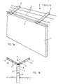
- Fig. 1a eine perspektivische Ansicht eines Mauerabschnittes, ausgerüstet mit einem ersten Ausführungsbeispiel der Vorrichtung nach den Erfindung,
- Fig. 1b eine schematische Seitenansicht eines Zaunpfahles, der eine Vorrichtung nach der Erfindung gemäss einem zweiten Ausführungsbeispiel trägt,
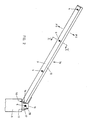
- Fig. 2 eine Seitenansicht eines verschlossenen Auslegers mit eingelegten Detektionsdrähten gemäss einem ersten Ausführungsbeispiel,
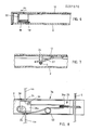
- Fig. 3 eine teilweise geschnittene Detail-Seitenansicht des geöffneten Auslegers,
- Fig. 4 eine Teilansicht des geöffneten Auslegers von oben,
- Fig. 5 einen Schnitt entlang der Linie V-V in Fig. 2,
- Fig. 6 einen Teillängsschnitt durch das freie Ende des Auslegers,
- Fig. 7 einen Teillängsschnitt durch einen Mittelabschnitt des Auslegers,
- Fig. 8 eine schematische Darstellung einer alternativ möglichen Führung des Detektionsdrahtes.
- Fig. 9 eine Teilansicht eines Zauns mit einem am Zaunpfosten montierten Ausleger gemäss einem zweiten Ausführungsbeispiel,
- Fig. 10 eine schematische Seitenansicht dieses zweiten Ausführungsbeispiels eines Auslegers,
- Fig. 11 einen Teillängsschnitt durch den Ausleger von Fig. 10,
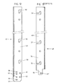
- Fig. 12 eine teilweise geschnittene Seitenansicht eines Auslegerarms,
- Fig. 13 eine teilweise geschnittene Seitenansicht eines Deckprofils,
- Fig. 14 eine teilweise geschnittene Ansicht des Supports,
- Fig. 15 einen Querschnitt durch den Ausleger im Bereich der Schwenkachse, und
- Fig. 16 eine perspektivische, schematische Ansicht einer Manschette.
- 1a is a perspective view of a wall section, equipped with a first embodiment of the device according to the invention,
- 1b is a schematic side view of a fence post, which carries a device according to the invention according to a second embodiment,
- 2 is a side view of a closed cantilever with inserted detection wires according to a first embodiment,
- 3 is a partially sectioned detailed side view of the opened boom,
- 4 is a partial view of the open boom from above,
- 5 shows a section along the line VV in FIG. 2,
- 6 is a partial longitudinal section through the free end of the boom,
- Fig. 7 shows a partial longitudinal section through a central section the boom,
- 8 shows a schematic illustration of an alternatively possible guidance of the detection wire.
- 9 is a partial view of a fence with a boom mounted on the fence post according to a second embodiment,
- 10 is a schematic side view of this second embodiment of a boom,
- 11 is a partial longitudinal section through the boom of FIG. 10,
- 12 is a partially sectioned side view of a cantilever arm,
- 13 is a partially sectioned side view of a cover profile,
- 14 is a partially sectioned view of the support,
- Fig. 15 shows a cross section through the boom in the region of the pivot axis, and
- 16 is a perspective, schematic view of a cuff.
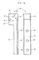
In den Fig. 1a und 1b sind schematisch Ausschnitte aus Absperrvorrichtungen gezeigt, die ein Gelände gegen unbefugtes Eindringen oder Verlassen schützen. Gemäss Fig. 1a ist eine Mauer 1 vorgesehen, die mit einem Übersteigschutz versehen ist, welcher generell mit 2 bezeichnet ist. Dieser besteht aus einer Anzahl von im Winkel zur Ebene der Mauer 1 verlaufenden Auslegern 3, die in regelmässigen Abständen auf der Mauerkrone verankert sind. Zwischen den Auslegern 3 sind Detektionsdrähte 4 gespannt; jene sind in bekannter Weise mit einer Alarmeinrichtung wirkungsverbunden, so dass bei einer Beschädigung oder Zerstörung eines der Drähte 4 ein Alarmsignal ausgelöst wird. Im weiteren ist ein Detektionsdraht 5 vorhanden, der von Fussteil zu Fussteil der Ausleger 3 verläuft; dessen Zweck wird im nachfolgenden noch erläutert werden.1a and 1b schematically show sections of shut-off devices which protect a site against unauthorized entry or exit. 1a, a
In der Fig. 1b ist ein einzelnes Zaunpfostenelement 6 in einer schematischen Seitenansicht zu sehen. Zwischen solchen Pfostenelementen 6 erstreckt sich ein (nicht dargestellter) Zaun, der z.B. mittels einzelner, sich von Pfosten zu Pfosten erstreckender Detektionsdrähte 8 gegen Beschädigung oder Zerstörung geschützt sein kann. Der Kopf des Pfostens 6 trägt einen Ausleger 7, der mit zwei sich in entgegengesetzten Richtungen erstrekkenden Auslegerarmen 7a und 7b versehen ist. Das Mittelteil des Auslegers 7 ist wiederum mit einem Detektionsdraht 5 ausgerüstet, während jeweils zwischen den Armen 7a bzw. 7b benachbarter Pfosten 6 Detektionsdrähte 4 gespannt sind.In Fig. 1b, a single
Wesentlich ist in beiden Fällen, dass die Ausleger 3 bzw. Auslegerarme 7a und 7b unter relativ geringen, jedoch betragsmässig bekannten und reproduzierbaren Kräfteeinwirkungen verschwenkbar sind und dass bei einer solchen Verschwenkung ein Alarmsignal ausgelöst wird.It is essential in both cases that the
In der Fig. 2 ist ein erstes Ausführungsbeispiel eines Auslegers 3 in einer schematischen Seitenansicht dargestellt. In Verbindung mit Fig. 5 ist erkenntlich, dass der Auslegerarm 3a ein langgestrecktes, U-förmiges Hohlprofil 9 aufweist, welches über eine Sollbiegestelle 10 mit einem Endstück 11 verbunden ist. Das Endstück 11 ist auf der Krone z.B. einer Mauer 1 fest verankert. Der Auslegerarm 3a schliesst dabei mit der Horizontalen einen Winkel von beispielsweise ca. 30° ein. Das U-förmige Hohlprofil 9 des Auslegerarms 3a ist mittels eines ebenfalls U-förmigen Deckprofil 12 verschlossen, dessen Schenkel 13a und 13b die Schenkel 14a und 14b des Armprofils 9 übergreifen. Das Endstück 11 ist ebenfalls im Querschnitt U-förmig ausgebildet, wobei die Stirnkanten 14 der Schenkel 15 abgeschrägt sind. Der Zweck dieser Massnahme besteht darin, dass sich die Schenkel 13a bzw. 13b des Armprofils 9 nicht mit den Schenkeln 15 überlappen; damit ist es nicht möglich, z.B. durch Ansetzen einer Schraubzwinge eine Relativbewegung zwischen Endstück 11 und Auslegerarm 3a zu blockieren.2 shows a first exemplary embodiment of a
Das Deckprofil 12 besitzt ein fest angebrachtes, z.B. angeschweisstes Endteil 16, welches zwei seitliche Schenkel 17 be sitzt, die die Schenkel 15 des Endstückes 11 übergreifen. Im übrigen schliesst das Endteil 16 das U-förmige Endstück 11 vollständig, so dass dessen Inneres gegen unbefugten Zugriff geschützt ist. Gleiches gilt natürlich auch für das Deckprofil 12, welches das Armprofil 9 bedeckt.The
Die Befestigung bzw. Sicherung des Deckprofiles 12 samt Endteil 16 am Armprofil 9 bzw. Endstück 11 geschieht auf folgende Weise:The
Einerseits ist das freie Ende des Armprofils 9 mit einer innenseitig gelegenen, parallel und im Abstand zum Steg des U-Profils 9 verlaufenden Verankerungsplatte 18 versehen, die sich zwischen den beiden Schenkeln 14a und 14b des U-Profils 9 erstreckt. Das freie Ende des Deckprofils seinerseits ist mit einer Verankerungszunge 19 ausgestattet, die durch das vorstehende Ende eines am Steg des Deckprofils 12 befestigten Verankerungsprofiles 22 gebildet ist. Wie aus Fig. 6 ersichtlich ist die Anordnung so gewählt, dass die Zunge 19 die Platte 18 untergreift, wenn das Deckprofil 12 auf das Armprofil 9 aufgesetzt ist. Ein Abheben des Deckprofils 12 vom Armprofil 9 ist also nur möglich, wenn das Deckprofil 12 zuvor in Richtung des Pfeiles P₁ soweit verschoben wurde, dass die Zunge 19 freigegeben ist.On the one hand, the free end of the
Andererseits ist jeder der beiden Schenkel 17 des Endteiles 16 mit einer ungefähr mittig angeordneten Bohrung 20 versehen. Die Schenkel 15 des Endstückes 11, welche von den Schenkeln 17 des Endteiles 16 übergriffen werden, sind ebenfalls mit Bohrungen 21 ausgestattet, die so gelegen sind, dass bei aufgesetztem Deckprofil 12 samt Endteil 16 Deckungsgleichheit zwischen den Bohrungen 20 und 21 herrscht. Durch die Bohrungspaare 20 und 21 ist der zuvor schon erwähnte Detektionsdraht 5 gezogen.On the other hand, each of the two
Ein Entfernen des Deckprofils 12 vom Auslegerarm 3a ist also nicht möglich, ohne den Detektionsdraht 5 zu zerstören, da ein Ausfahren der Zunge 19 ein Abscheren des Drahtes 5 und damit eine Alarmauslösung zur Folge hätte.It is therefore not possible to remove the
Die Sollbiegestelle 10 ist durch einen Lappen 23 gebildet, der am Steg des U-Profils, welches das Endstück 11 bildet, angeschraubt ist und dessen Querschnitt gegenüber demjenigen des U-Profils verringert ist. Im Sinne einer leichten Auswechselbarkeit bzw. Reparierbarkeit ist eine Schraubverbindung gegenüber z.B. einer Schweissverbindung vorzuziehen. Die Gefahr eines unbefugten Lösens der Schrauben besteht nicht, da diese im Inneren des Endstückes 11 liegen und somit nicht zugänglich sind, ohne das Deckprofil 12 zu entfernen, was unbefugterweise aber wiederum eine Alarmauslösung zur Folge hätte.The
Die beiden Schenkel 14a und 14b sind mit einander gegenüberliegenden Schlitzen 24 versehen, in welche die eingangs erwähnten Detektionsdrähte 4 eingelegt sind. Bei aufgesetztem Deckprofil 12 sind die Schlitze 24 durch die Kanten der Schenkel 13a und 13b verschlossen, so dass die Drähte 4 nicht unbefugt herausgenommen werden können. Andererseits ermöglichen die Schlitze, während der Montage der Vorrichtung, ein sehr bequemes Einlegen der Drähte 4. Auch im Fall einer Reparatur, wenn ein Auslegerarm 3a ausgewechselt werden muss, ist ein erleichtertes Arbeiten möglich, da noch intakt gespannte Detektionsdrähte 4 nicht demontiert oder unterbrochen werden müssen, wenn ein neuer Auslegerarm montiert wird.The two
Im Inneren des Auslegers 3, gegen unbefugten Zugriff also geschützt, ist ein Abscherorgan 25 vorgesehen, das von einem der Detektionsdrähte 4 durchdrungen ist. Das Abscherorgan 25 wird bei einer Verschwenkung des Auslegerarmes 3a betätigt, sodass der betreffende Detektionsdraht 4 durchgetrennt und somit Alarm ausgelöst wird.In the interior of the
Das Abscherorgan besitzt zwei in geringem Abstand parallel nebeneinander verlaufende, starre Scherplatten 26, die z.B. durch die aufrechtstehenden Schenkel eines am Steg des Armprofiles 9 befestigten L-Profiles 27 gebildet sein können. Zwischen den beiden starren Scherplatten 26 ist eine bewegliche Scherplatte 28 gelagert, die einen abgewinkelten, sich gegen das Innere des Endstückes 11 erstreckenden Fortsatz 29 trägt. Dieser Fortsatz 29 ist an einem Steg 30 befestigt, der parallel in der Mitte zwischen den beiden Schenkeln 15 des Endstückes 11 angeordnet ist. Die Befestigung erfolgt vorzugsweise mittels lösbarer Schrauben 31, um eine Reparatur bzw. ein Auswechseln zu ermöglichen.The shearing member has two
Das gesamte Abscherorgan 25 ist gegenüber der Mittellängsachse des Armprofils 9 seitlich etwas versetzt angeordnet. Damit ist erreicht, dass die bewegliche Scherplatte 28 bzw. deren Fortsatz 29 bündig an der einen der beiden Seitenflächen des Steges 30 anliegt. Somit kann bei Bedarf an dasselbe Endstück 11 ein weiterer, identisch ausgebildeter Auslegerarm 3a von der anderen Seite her montiert werden; der Fortsatz der beweglichen Scherplatte jenes symmetrisch angebrachten Armes wird dann auf der gegenüberliegenden Seite des Steges 30 anliegen. Mit einem einzigen, gemeinsamen Endstück 11 und einer einheitlichen Auslegerarm-Konstruktion können also einseitige Uebersteigsicherungen (z.B. gemäss Fig. 1a) oder doppelseitige Uebersteigsicherungen (z.B. gemäss Fig 1b) realisiert werden. Auch eine nachträgliche Erweiterung von einseitig auf doppelseitig ist ohne Probleme möglich.The
Sowohl die beiden starren Scherplatten 26 als auch die bewegliche Scherplatte 28 besitzen eine Mehrzahl von Bohrungen. Die Bohrungen in den beiden starren Scherplatten 26 sind konstruktiv bedingt deckungsgleich und decken sich ihrerseits mit den Bohrungen in der beweglichen Scherplatte 28, sofern diese im Ruhezustand ist, d.h. solange der Auslegerarm 3a nicht gegenüber dem Endstück 11 verschwenkt ist.Both the
Im einzelnen sind zwei Bohrungsgruppen 32a und 32b vorhanden, die vergleichsweise grossen Durchmesser haben und die zur vorübergehenden Aufnahme von Sicherungsstiften 33 dienen. Damit ist bei der Montage bzw. der Reparatur der Vorrichtung gewährleistet, dass der Auslegerarm 3a nicht versehentlich um die Sollbiegestelle 10 herum verschwenkt wird. Ferner sind zwei Bohrungsgruppen 34a und 34b vorgesehen, die zur Aufnahme eines Detektionsdrahtes 4 dienen. Im Ausführungsbeispiel gemäss Fig. 4 ist nur ein Detektionsdraht 4 durch die Bohrungen 34a geführt, doch mag es in manchen Fällen vorteilhaft sein, noch eine freie Bohrungsgruppe 34b zur Verfügung zu haben, durch die ein weiterer Detektionsdraht geführt werden kann.Specifically, there are two groups of
Es leuchtet nun ein, dass bei einer Verschwenkung des Auslegerarmes 3a, sei es in Richtung P₂, sei es in Richtung P₃ (Fig. 2 und 3), eine Relativbewegung zwischen den starren Scherplatten 26 und der beweglichen Scherplatte 28 erfolgen muss. Damit wird aber der durch die Bohrungen 34a geführte Sicherungsdraht 4 abgeschert oder zumindest soweit beschädigt, dass eine Alarmauslösung erfolgt. Ein Blockieren des Abscherorganes 25 durch mechanische Mittel oder durch Kleber kann nicht erfolgen, da sich die gesamte Abscherapparatur im geschützten Inneren des hohlen Ausleger 3 befindet. Einer Spaltkorrosion kann durch Fettung vorgebeugt werden.It now makes sense that when the
Schliesslich ist noch eine Mehrzahl von vergleichsweise kleinen, weiteren Bohrungsgruppen 35 vorgesehen. Diese dienen dazu, von Fall zu Fall dünne Stifte 36 aus Kupfer oder einem ähnlichen, weichen Material aufzunehmen. Die Sollbiegestelle 10 ist nämlich relativ weich, d.h. es ist nur ein sehr geringes Dreh moment erforderlich, um den Auslegerarm zu verschwenken, was unter Umständen unerwünscht sein kann. Um nun die Ansprecheigenschaften der Vorrichtung genau und reproduzierbar einstellen zu können, werden eine oder mehrere der Bohrungsgruppen 35 mit den besagten Kupferstiften 36 versehen.Finally, a plurality of comparatively small, further groups of
Jede Bohrungsgruppe 35 hat einen unterschiedlichen Abstand zur theoretischen Verschwenkungsachse durch die Sollbiegestelle 10. Damit kann in sehr feinen Abstufungen eingestellt werden, welches Drehmoment zur Verschwenkung des Auslegerarmes 3a und damit zur Alarmauslösung erforderlich ist, indem eine oder eine Kombination von Bohrungsgruppen 35 mit Kupferstiften 36 ausgerüstet wird. Auf diese Weise lassen sich Auslösemomente im Bereich von ca. 20 bis ca. 150 Nm einstellen, die auf lange Sicht erhalten bleiben und so die zuverlässige Funktion der Vorrichtung gewährleisten, bei nur minimer Gefahr einer Fehlalarm-Auslösung.Each
Aus der Schnittdarstellung in Fig. 7 ist ersichtlich, dass das Deckprofil 12 innenseitig mit abstehenden, federnden Zungen 37 versehen werden kann, und zwar in denjenigen Bereichen, wo die Schlitze 24 im Armprofil 9 ausgebildet sind. Dadurch lässt sich eine weitere Fehlalarm-Sicherheit und ein zuverlässigeres Langzeitverhalten der Vorrichtung erzielen, insofern, als die Sicherungsdrähte 4 gegen Vibrationen geschützt sind, die eine vorzeitige Alterung oder Beschädigung verursachen könnten.From the sectional view in FIG. 7 it can be seen that the
In der Fig. 4 ist angedeutet, wie ein Detektionsdraht 4 durch einen der Schlitze 24 hindurchgeführt, zur Bohrungsgruppe 34a umgelenkt und durch diese hindurchgeführt und zum gegenüberliegenden Schlitz 24 sowie durch diesen aus dem Armprofil 9 herausgeführt ist. Unter Umständen kann es aber wünschenswert sein, den Detektionsdraht 4 im Inneren des Auslegerarmes 3a von Zugkräften zu entlasten. Fig. 8 zeigt eine solche Lösung.FIG. 4 indicates how a
Der Detektionsdraht tritt durch den Schlitz 24 in das Innere des Auslegerarms 3a ein und wird im Bereich der Eintrittstelle durch ein Klemmorgan 38 gehalten; letzteres kann durch eine Platte 38a gebildet sein, die mit zwei Schrauben an der Innenseite des Steges des Armprofiles 9 gehalten ist. Von der Platte 38a verläuft der Detektionsdraht 4a zum Abscherorgan 25, tritt dort durch die Bohrungsgruppe 34a hindurch und verläuft, unter Bildung einer Schlaufe 40, wiederum zum Klemmorgan 38, von wo aus er den Auslegerarm 3a durch den Schlitz 24 verlässt. Der Vorteil einer solchen Anordnung ist, dass bei einer Reparatur der Vorrichtung, nachdem der Detektionsdraht 4a durchtrennt worden ist, genügend Vorrat von der Schlaufe 40 her zur Verfügung steht, um den Draht 4a wieder zusammenzuspleissen, ohne dass der gesamte Draht 4a, der sich vielleicht über mehrere hundert Meter erstreckt, demontieren oder auswechseln zu müssen.The detection wire enters the interior of the
In der Fig. 9 ist als weiteres Ausführungsbeispiel einer erfindungsgemässen Vorrichtung ein Ausschnitt aus einem Zaun 41 gezeigt, mit einem Zaunpfosten 42, der an seinem oberen Ende ei nen gesamthaft mit 43 bezeichneten Ausleger trägt. Die Gesamtanordnung kann dabei ähnlich sein wie im Zusammenhang mit Fig. 1a beschrieben, d.h. zwischen den Auslegern 43 erstrecken sich Spanndrähte 44 und ein durchgehender Detektionsdraht 45 verläuft von einem Ausleger 43 zum nächsten.FIG. 9 shows, as a further exemplary embodiment of a device according to the invention, a section of a
Der Ausleger 43, auf dessen Aufbau im folgenden noch näher eingegangen werden wird, besteht im wesentlichen aus einem Befestigungsteil 46, der fest am Zaunpfosten 42 verankert ist, und einem schwenkbar daran gelagerten Auslegerarmteil 47, der die Spanndrähte 44 aufnimmt. Der Detektionsdraht 45 ist dabei jeweils mit den Befestigungsteilen 46 in noch zu erläuternder Weise wirkungsverbunden.The
Wesentlich ist auch bei diesem Ausführungsbeispiel wieder, dass die Ausleger 43 bzw. Auslegerarmteile 47 unter relativ geringen, jedoch betragsmässig bekannten und reproduzierbaren Kräfteeinwirkungen verschwenkbar sind und dass bei einer solchen Verschwenkung ein Alarmsignal ausgelöst wird.It is also essential in this exemplary embodiment that the
In der Fig. 10 ist ein zweites Ausführungsbeispiel eines Auslegers 43 in einer schematischen Seitenansicht dargestellt. Der Auslegerarmteil 47 umfasst ein langgestrecktes, U-förmiges Hohlprofil 48, das mittels eines ebenfalls langgestreckten, U-förmigen Deckprofil 49 mit etwas geringeren Abmessungen verschlossen ist. Beide Profile 48 und 49 sind mit Schlitzen 50 bzw. 51 versehen, um die Spanndrähte 44 aufzunehmen. Der Aus legerarmteil 47 ist schwenkbar am Befestigungsteil 46 gelagert, und im Bereich der Verbindungsstelle zwischen Auslegerarmteil 47 und Befestigungsteil 46 ist eine zweiteilige Manschette 52 angebracht, deren Zweck noch erläutert werden wird. Jedenfalls ist so die Lage der Schwenkachse zwischen Auslegerarmteil 47 und Befestigungsteil 46 von aussen her nicht sichtbar und vor allem auch nicht zugänglich. Die beiden Teile der Manschette 52 können mit Schrauben 70 aneinander befestigt sein; eine besondere Sicherung dieser Schrauben erübrigt sich, da die Manschette 52 wegen des sie senkrecht zur Demontagerichtung durchdringenden Detektionsdrahtes 45 nicht auseinandergenommen werden kann, ohne den Detektionsdraht 45 zu beschädigen bzw. zerstören und damit den Alarm auszulösen.10 shows a second exemplary embodiment of a
Der Aufbau des eigentlichen Auslegerarmteiles, nämlich des U-Profiles 48, und des ebenfalls U-förmigen Deckprofiles 49 gehen aus den Fig. 12 und 13 hervor. Die beiden Schenkel 53 des Armprofils 48 und die beiden Schenkel 54 des Deckprofiles 49 sind mit den bereits erwähnten, L-förmigen Schlitzen 50 bzw. 51 zur Aufnahme der Spanndrähte 44 versehen. Koinzidierende Bohrungen 55 bzw. 56, im Deckprofil 49 vorzugsweise als Gewindebohrungen ausgebildet, dienen dazu, die beiden Profile im Sinn einer mechanischen Fixierung und Verstärkung miteinander zu verbinden, mit Hilfe nicht dargestellter Schrauben. Die Breite des Deckprofils 49 ist etwas geringer als diejenige des Armprofils 47, damit ersteres in das letztere eingesetzt werden kann.The structure of the actual cantilever arm part, namely the U-profile 48, and the likewise
Das Armprofil 47 besitzt an seinen beiden Schenkeln Fortsätze 57, in deren Bereich eine Mehrzahl von Bohrungsgruppen vorgesehen sind. Eine erste Bohrungsgruppe 58 dient zur Aufnahme eines Stiftes 59 (Fig. 11), der als Schwenkachse zur Verbindung zwischen Armteil 47 und Befestigungsteil 46 dient. Eine zweite Bohrungsgruppe 60 dient dazu, einen Sicherungsstift (nicht dargestellt) aufzunehmen, um den Armteil 47 bei der Montage der Vorrichtung gegen Verschwenkung gegenüber dem Befestigungsteil 46 zu schützen. Es versteht sich, dass dieser Sicherungsstift bei Inbetriebnahme der Vorrichtung entfernt wird. Eine dritte Bohrungsgruppe 61 ist dazu vorgesehen, den Detektionsdraht 45 aufzunehmen. Eine Mehrzahl von vierten Bohrungsgruppen 62 schliesslich dienen dazu, Scherstifte, z.B. aus Kupfer, aufzunehmen, um das Ansprechverhalten bei Verschwenkung der Auslegerkonstruktion festzulegen.The
Das Deckprofil 49 ist an seinen beiden Schenkeln 63 ebenfalls mit Fortsätzen 64 versehen, die eine Bohrungsgruppe 61ʹ aufweisen. Die Lage der Bohrungen 61ʹ ist so gewählt, dass sie sich mit den Bohrungen 61 in den Fortsätzen 57 des Armprofils 47 decken, wenn das Deckprofil 49 in das Armprofil 47 eingesetzt ist. Mit anderen Worten: Der Detektionsdraht 45 durchdringt, bei eingesetztem Deckprofil 49, sowohl die Bohrungen 61 im Armprofil 47 als auch die Bohrungen 61ʹ im Deckprofil 49. Durch die gegensinnige Anrodnung der L-förmigen Schlitze 50 bzw. 51 im Armprofil 47 einerseits und im Deckprofil 49 andererseits ist dadurch erreicht, dass das Deckprofil 49 nicht vom Armpro fil 47 entfernt werden kann, sobald der Detektionsdraht 45 eingelegt ist, weil eine Entfernung des Deckprofils 49 vom Armprofil 47 gezwungenermassen eine gegensinnige Verschiebung der beiden Profile 47 und 49 in Längsrichtung erfordert, damit die in die Schlitze 50 bzw. 51 eingelegten Spanndrähte 44 aus den Schlitzen 51 im Deckprofil 49 ausgefahren werden können. Eine solche Verschiebung würde aber die Bechädigung bzw. Zerstörung des Detektionsdrahtes 45 nach sich ziehen, wodurch ein Alarm ausgelöst würde.The
Die L-förmige Ausbildung der Schlitze 50 im Auslegerarmprofil 47 vereinfachen auch die Initialmontage der Vorrichtung, indem die Spanndrähte, die Detektionsdrähte, das Geflecht usw. bei fixiertem Auslegerarm auf einfache Art eingelegt werden können und dabei gegen versehentliches Herausfallen gesichert sind, bis das Deckprofil 49 eingeführt und befestigt ist.The L-shaped design of the
Der Befestigungsteil 46 umfasst gemäss Fig. 14 einen Rumpfabschnitt 74, mit Bohrungen 66 ausgerüstet und dazu bestimmt, im Beispielsfall an eine vertikale Seitenfläche eines Zaunpfostens 42 etwa gemäss der Darstellung in Fig. 9 befestigt zu werden. Dazu werden zweckmässigerweise Sabotage-sichere Schrauben verwendet, auf die hier nicht näher eingegangen wird. Ferner besitzt der Befestigungsteil 46 einen Kopfabschnitt 65, der im Querschnitt U-förmig gestaltet und den Ausleger 43 aufzunehmen bestimmt ist. Der Kopfabschnitt 65 ist an seinen Schenkeln mit einer Mehrzahl von Bohrungsgruppen ausgerüstet, die in Grösse und Anordnung in etwa den vorstehend diskutierten Bohrungsgruppen in den Fortsätzen 57 des Armteiles 47 entsprechen.According to FIG. 14, the
So ist eine erste Bohrungsgruppe 58ʹ vorhanden, die zur Aufnahme des bereits erwähnten, als Drehachse wirkenden Stiftes 59 vorgesehen ist, eine zweite Bohrungsgruppe 60ʹ, die den ebenfalls bereits erwähnten Sicherungsstift bei der Montage aufnimmt, eine dritte Bohrungsgruppe 61ʺ, durch die der Detektionsdraht 45 hindurchgeführt ist, und vierte Bohrungsgruppen 62ʹ zur Aufnahme der nach Bedarf einzusetzenden Scherstifte. Wie aus der Fig. 11 ersichtlich ist, decken sich die entsprechenden Bohrungsgruppen, wenn der Ausleger 43 in der Ruhelage ist, etwa wie in Fig. 9 gezeigt.There is a first group of holes 58ʹ, which is intended to receive the
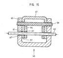
Wie aus der Schnittdarstellung gemäss Fig. 15 ersichtlich ist, wirken der Kopfabschnitt 65 des als Befestigungsteiles dienenden Supports 46 und die Fortsätze 57 der Schenkel 53 des Armteiles 47 in der Art eines Abscherorganes zusammen. Wenn der Auslegerarmteil 47 um den Stift 59 verschwenkt wird, wird der durch die Bohrungen 60 und 60ʺ hindurchgezogene Detektionsdraht 45 gequetscht oder abgeschert, was zu einer Alarmauslösung führt. Wenn ein sehr feines Ansprechverhalten realisiert werden soll, ist es möglich, eine der Bohrungen 60 im Fortsatz 57 des Armteiles 47 grösser auszubilden oder durch eine durchgehende Durchbrechung zu ersetzen, so dass der Detektionsdraht 45 nur an einer Stelle gequetscht bzw. durchtrennt wird, wenn der Ausleger 43 verschwenkt wird. Im übrigen kann, wie schon im Zusam menhang mit dem ersten Ausführungsbeispiel erwähnt, das Auslöseverhalten durch Einsetzen von einem oder mehreren Kupferstiften in die Bohrungen 62 und 62ʹ beeinflusst werden.15, the
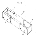
Um eine noch weiter verbesserte Sabotagesicherheit zu erreichen, wird die Auslegerkonstruktion mit einer Manschette 52 gesichert, die z.B. die in der Fig. 16 dargestellte Form haben kann. Die Manschette 52 besteht aus einem Aussenteil 67 und einem Innenteil 68, wobei der Innenteil 68 in den Aussenteil 67 eingeschoben wird. Die zusammengesetzte Manschette 52 umschliesst den Kopfteil 65 des Supports sowie den Fussabschnitt des darin schwenkbar aufgenommenen Auslegers 43 derart, dass die Manschetten-Aussenflächen einen gewissen Abstand zu den Oberflächen des Supports 46 und des Auslegers 43 eingehalten. Damit ist gewährleistet, dass die Verschwenkbarkeit des Auslegers 43 nicht einfach durch Ansetzen einer Schraubzwinge blockiert werden kann, da die Manschettenwände, auch bei stärkstem Anziehem der Schraubzwinge, nur soweit durchgebogen werden, dass sie die scharnierartige Gelenkverbindung nicht berühren.In order to achieve an even better security against sabotage, the boom construction is secured with a
Die beiden Teile 67 und 68 der Manschette 52 weisen an gegenüberliegenden Seitenflächen Bohrungen 69 und 69ʹ auf, die sich bei zusammengesetzter Manschette 52 decken. Weiter ist deren Lage so gewählt, dass sie mit den Bohrungen 61 im Auslegerarmteil 47, mit den Bohrungen 61ʹ im Deckprofil 49 und den Bohrungen 61ʺ im Support 46, durch die alle der Detektionsdraht 45 hindurchgeführt ist, koinzidieren. Somit kann der Detektionsdraht, bei aufgesetzter Manschette 52, ebenfalls durch die Bohrungen 69 und 69ʹ hindurchgezogen werden, um die Manschette 52 gegen Demontage zu sichern.The two
Auch bei diesem zweiten Ausführungsbeispiel ist das Abscher- bzw. Quetschorgan im Inneren der Auslegerkonstruktion angeordnet und von aussen nicht zugänglich, selbst wenn keine Manschette 52 aufgesetzt ist. Mit Manschette 52 ist eine praktisch vollständige Kapselung der funktionswesentlichen Teile der Auslegerkonstruktion erreicht, die von einem Saboteur, wenn überhaupt, nur mit grossem Zeitaufwand überwunden werden kann.In this second exemplary embodiment, too, the shearing or squeezing member is arranged inside the boom construction and is not accessible from the outside, even if no
Zusammenfassend seien nochmals die wichtigsten Eigenschaften und Vorteile der erfindungsgemässen Vorrichtung hervorgehoben:
- Es ist eine grosse Sabotagesicherheit gewährleistet. Es sind keine aussenliegenden, überlappenden Elemente vorhanden, die mechanisch (z.B. durch eine Schraubzwinge) blokkiert werden können, um ein Verschwenken des Auslegers zu verhindern. Ferner ist auch kein aussenliegendes Scharnier oder Gelenk vorhanden, das durch Klebstoff oder Korrosion blockiert werden könnte.
- Die Ansprecheigenschaften sind genau definiert und reproduzierbar. Der Auslegerarm kann in beiden Richtungen verschwenkt werden, wobei die Alarmauslösung in jedem Fall zu verlässig anspricht. Die Auslösekraft ist durch zweckmässige Auswahl und Anordnung der Scherstifte in einem weiten Bereich einstellbar, wobei die einmal vorgewählte Auslösekraft über lange Zeit erhalten bleibt. Damit ist die Vorrichtung an nahezu jedes Sicherheitskonzept anpassbar und die Gefahr der Auslösung eines Fehlalarmes ist minimiert.
- Die Vorrichtung ist leicht reparierbar. Bei nur geringer Verschwenkung ist es lediglich erforderlich, die Scherstifte im Abscherorgan sowie den Detektionsdraht, der sich durch die Befestigungsteile erstreckt, auszuwechseln bzw. letzteren zu reparieren; bei starker Deformation kann ein einzelner Auslegerarm leicht ersetzt werden, da die Spanndrähte, das Geflecht usw. aus diesem ausfahrbar sind. Diese Eigenschaft ist auch bei der Initialmontage günstig, da die Spanndrähte, das Geflecht oder dgl. nur eingelegt zu werden brauchen.
- Die Vorrichtung ist einfach aufgebaut und preisgünstig herstellbar. Alle Teile sind aus Blech, vorzugsweise rostfreiem, gegebenenfalls gehärtetem Stahlblech gefertigt und können durch Stanzen und Biegen in die gewünschte Form gebracht werden. Ein einziges Endstück kann mit einem oder zwei Auslegerarmen versehen werden, wobei auch eine nachträgliche Aufrüstung möglich ist. Dabei ist jedenfalls nur ein einziger Detektionsdraht zur Detektion einer Entfernung der Abdeckung oder eines Demontageversuchs der Auslegerkonstruktion erforderlich.In summary, the most important properties and advantages of the device according to the invention are again emphasized:
- A high level of security against sabotage is guaranteed. There are no external, overlapping elements that can be blocked mechanically (e.g. by a screw clamp) to prevent the boom from pivoting. Furthermore, there is no external hinge or joint that could be blocked by adhesive or corrosion.
- The response properties are precisely defined and reproducible. The cantilever arm can be swiveled in both directions, whereby the alarm is triggered in any case responds reliably. The triggering force can be adjusted within a wide range by appropriate selection and arrangement of the shear pins, whereby the triggering force which has been preselected is retained over a long period of time. The device can thus be adapted to almost any safety concept and the risk of triggering a false alarm is minimized.
- The device is easily repairable. With only a slight pivoting, it is only necessary to replace the shear pins in the shear member and the detection wire which extends through the fastening parts, or to repair the latter; in the event of severe deformation, a single cantilever arm can easily be replaced, since the tensioning wires, the braid, etc. can be extended from it. This property is also favorable during the initial assembly, since the tension wires, the braid or the like only need to be inserted.
- The device is simple in construction and inexpensive to manufacture. All parts are made of sheet metal, preferably rustproof, possibly hardened steel sheet and can be shaped into the desired shape by punching and bending. A single end piece can be provided with one or two extension arms, whereby a subsequent upgrade is also possible. In any case, only a single detection wire is required to detect a removal of the cover or an attempt to dismantle the boom construction.
Eine nochmals verbesserte Sicherung eines Areals gegen Eindringen kann mit einem Sicherheitszaun erreicht werden, der mit den zuvor beschrieben Auslegerkonstruktionen ausgerüstet ist und ein Geflecht aus Detektionsdrähten aufweist, die bei deren Zerstörung oder Beschädigung einen Alarm auslösen. Um ein Hindurchzwängen zwischen der Oberkante des Zaunes 41 und den zwischen den Auslegern 43 verlaufenden, untersten Spanndrähten 44 (Fig. 9) zu vermeiden, kann das Geflecht des Zaunes 41 weiter hinaufgezogen und an den einzelenen Aulegern 43 befestigt werden, z.B. anstelle der untersten zwei oder drei Spanndrähte 44. Dadurch ist die unempfindlichste Stelle der Auslegerkonstruktion, nämlich der Bereich der Schwenkachse, ebenfalls optimal geschützt.A further improvement in securing an area against intrusion can be achieved with a security fence which is equipped with the above-described cantilever constructions and has a network of detection wires which trigger an alarm if they are destroyed or damaged. In order to avoid being forced between the upper edge of the
Claims (24)
Applications Claiming Priority (2)
| Application Number | Priority Date | Filing Date | Title |
|---|---|---|---|
| DE3706999 | 1987-03-05 | ||
| DE19873706999 DE3706999A1 (en) | 1986-03-15 | 1987-03-05 | Apparatus for securing fences or walls against unauthorised persons climbing over them |
Publications (2)
| Publication Number | Publication Date |
|---|---|
| EP0281516A2 true EP0281516A2 (en) | 1988-09-07 |
| EP0281516A3 EP0281516A3 (en) | 1990-05-23 |
Family
ID=6322285
Family Applications (1)
| Application Number | Title | Priority Date | Filing Date |
|---|---|---|---|
| EP88810094A Ceased EP0281516A3 (en) | 1987-03-05 | 1988-02-16 | Security device against non-authorized climbing of fences or walls |
Country Status (1)
| Country | Link |
|---|---|
| EP (1) | EP0281516A3 (en) |
Cited By (1)
| Publication number | Priority date | Publication date | Assignee | Title |
|---|---|---|---|---|
| FR2962836A1 (en) * | 2010-07-19 | 2012-01-20 | Eryma Security Systems | Intrusion detection device for e.g. fence, has detection circuit electrically connected to arm and detection cable to detect contact between detection member and cable, where member is in contact with cable when arm is in alarm position |
Citations (4)
| Publication number | Priority date | Publication date | Assignee | Title |
|---|---|---|---|---|
| US4081177A (en) * | 1977-03-10 | 1978-03-28 | The United States Of America As Represented By The Secretary Of The Air Force | Break-away outrigger |
| DE2717906A1 (en) * | 1977-04-22 | 1978-10-26 | Ernst Blaser | Security alarm for fence - has switch tripped by movement of spring supported Y=shaped top rail |
| DE3211647A1 (en) * | 1982-03-30 | 1983-10-06 | Schulz Celler Drahtwaren | Device on fences or the like which serves for triggering a signal |
| FR2579350A1 (en) * | 1985-03-22 | 1986-09-26 | Bollore Louis Henri | Device forming a tilting flap used especially for closing off a space to be protected |
-
1988
- 1988-02-16 EP EP88810094A patent/EP0281516A3/en not_active Ceased
Patent Citations (4)
| Publication number | Priority date | Publication date | Assignee | Title |
|---|---|---|---|---|
| US4081177A (en) * | 1977-03-10 | 1978-03-28 | The United States Of America As Represented By The Secretary Of The Air Force | Break-away outrigger |
| DE2717906A1 (en) * | 1977-04-22 | 1978-10-26 | Ernst Blaser | Security alarm for fence - has switch tripped by movement of spring supported Y=shaped top rail |
| DE3211647A1 (en) * | 1982-03-30 | 1983-10-06 | Schulz Celler Drahtwaren | Device on fences or the like which serves for triggering a signal |
| FR2579350A1 (en) * | 1985-03-22 | 1986-09-26 | Bollore Louis Henri | Device forming a tilting flap used especially for closing off a space to be protected |
Cited By (1)
| Publication number | Priority date | Publication date | Assignee | Title |
|---|---|---|---|---|
| FR2962836A1 (en) * | 2010-07-19 | 2012-01-20 | Eryma Security Systems | Intrusion detection device for e.g. fence, has detection circuit electrically connected to arm and detection cable to detect contact between detection member and cable, where member is in contact with cable when arm is in alarm position |
Also Published As
| Publication number | Publication date |
|---|---|
| EP0281516A3 (en) | 1990-05-23 |
Similar Documents
| Publication | Publication Date | Title |
|---|---|---|
| DE3726098C2 (en) | ||
| EP0753457B1 (en) | Locking member | |
| CH698304B1 (en) | Cable anchor, in particular for rockfall or avalanche prevention structures. | |
| DE202005011463U1 (en) | Fall prevention device for roof workers, comprises threaded rod anchored in roof and secured inside support tube | |
| WO2016095906A1 (en) | Railing system | |
| DE3706999C2 (en) | ||
| EP0258585A2 (en) | Fence arrangement | |
| DE202018006106U9 (en) | Device for securing persons against falling | |
| EP3274971B1 (en) | Lattice mat for guiding a signal cable | |
| EP0611257A1 (en) | Climbing console | |
| EP2565328B1 (en) | Guide rail and vehicle retention system with same | |
| DE3211647C2 (en) | ||
| EP0281516A2 (en) | Security device against non-authorized climbing of fences or walls | |
| DE102009024551B4 (en) | Fence post with swiveling boom | |
| CH668300A5 (en) | Brake for steel cable - has shaped holes in plate to receive cable threaded through in zigzag pattern | |
| DE2919582A1 (en) | Demountable show fence support post - has additional holding rod offset to deflect mat from post alignment | |
| DE3837145C2 (en) | ||
| DE1534538A1 (en) | Security fence | |
| DE202007017491U1 (en) | Guard rail arrangement | |
| EP0261184B1 (en) | Rail, in particular for road bridges and similar | |
| DE3109234C2 (en) | Security fence | |
| DE2537242A1 (en) | SECURITY FENCE WITH ALARM DEVICE | |
| EP0644514B1 (en) | Alarm triggering device for fences | |
| EP0943745A2 (en) | Anchoring device for a tension bar in a reinforced concrete mass | |
| AT405852B (en) | GUIDE FOR TRAFFIC ROUTES |
Legal Events
| Date | Code | Title | Description |
|---|---|---|---|
| PUAI | Public reference made under article 153(3) epc to a published international application that has entered the european phase |
Free format text: ORIGINAL CODE: 0009012 |
|
| AK | Designated contracting states |
Kind code of ref document: A2 Designated state(s): AT BE CH DE ES FR GB GR IT LI LU NL SE |
|
| PUAL | Search report despatched |
Free format text: ORIGINAL CODE: 0009013 |
|
| AK | Designated contracting states |
Kind code of ref document: A3 Designated state(s): AT BE CH DE ES FR GB GR IT LI LU NL SE |
|
| 17P | Request for examination filed |
Effective date: 19900625 |
|
| 17Q | First examination report despatched |
Effective date: 19920901 |
|
| STAA | Information on the status of an ep patent application or granted ep patent |
Free format text: STATUS: THE APPLICATION HAS BEEN REFUSED |
|
| 18R | Application refused |
Effective date: 19930225 |