EP0281345A1 - Carter de turbine pour turbocompresseur de suralimentation - Google Patents
Carter de turbine pour turbocompresseur de suralimentation Download PDFInfo
- Publication number
- EP0281345A1 EP0281345A1 EP88301733A EP88301733A EP0281345A1 EP 0281345 A1 EP0281345 A1 EP 0281345A1 EP 88301733 A EP88301733 A EP 88301733A EP 88301733 A EP88301733 A EP 88301733A EP 0281345 A1 EP0281345 A1 EP 0281345A1
- Authority
- EP
- European Patent Office
- Prior art keywords
- partition wall
- turbine casing
- turbine
- slit
- inlet
- Prior art date
- Legal status (The legal status is an assumption and is not a legal conclusion. Google has not performed a legal analysis and makes no representation as to the accuracy of the status listed.)
- Withdrawn
Links
Images


Classifications
-
- F—MECHANICAL ENGINEERING; LIGHTING; HEATING; WEAPONS; BLASTING
- F01—MACHINES OR ENGINES IN GENERAL; ENGINE PLANTS IN GENERAL; STEAM ENGINES
- F01D—NON-POSITIVE DISPLACEMENT MACHINES OR ENGINES, e.g. STEAM TURBINES
- F01D9/00—Stators
- F01D9/02—Nozzles; Nozzle boxes; Stator blades; Guide conduits, e.g. individual nozzles
- F01D9/026—Scrolls for radial machines or engines
Definitions
- the present invention relates to turbine casings for turbochargers and is concerned with that type of casing which defines a volute or scroll shaped gas passage and includes at least one partition wall which divides the gas passage into a plurality of gas paths axially of the turbine axis, the outer periphery of the partition wall being substantially rigidly connected to the turbine casing.
- turbocharger turbine casing gases flowing through a gas inlet are induced to flow through a gas passage in a scrolled or volute portion of the casing thereby rotating a turbine wheel.
- a turbocharger has been proposed in which, in order to improve performance, the gas passage is divided into a plurality of gas paths axially of the turbine shaft and the gases are distributed into the gas paths depending on the variation of the gas flow rate thereby effectively utilising the dynamic pressure of the gases and thus enabling the turbine to be driven at a high degree of efficiency over a large range of gas flow rates.
- FIG 10 is a diagrammatic sectional elevation of a known turbocharger of the type described above and Figure 11 is a sectional view on the line XI-XI in Figure 10.
- This turbocharger includes a partition wall 2 which is integral with, and extends radially inwardly from, the circular inner surface of the turbine casing 1 so that the gas passage 3 is divided axially of the turbine shaft by the partition wall 2 into gas paths 3a and 3b which communicate with the turbine wheel 9.
- Figure 12 is a view similar to Figure 11 of a further known turbocharger which includes a separate partition wall 4 which is arranged so that substantially all of it can move freely in the radial direction within the turbine casing 1.
- the turbine casing 1 comprises two separate casing portions 1a and 1b which are welded together at 7 and abut one another in a radial plane 5 and define a continuous circumferential groove 6 in the inner periphery of the casing portions 1a and 1b.
- the outer periphery of the partition wall 4 is fitted into the groove 6 such that the partition wall 4, which divides the gas passage 3 into a plurality of gas paths, can be displaced in the radial direction.
- the scrolled portion of the turbine casing in both the constructions described above is in the form of a spiral so that its thermal expansion and deformation due to the heat of the exhaust gases are very complex.
- the gas passage 3 is divided into two gas paths by the partition wall 2 integral with the inner surface of the turbine casing
- movement of the periphery of the partition wall 2 is prevented by the turbine casing so that differential expansion of the turbine casing 1 and the partition wall 2 cannot be absorbed.
- thermal stresses are concentrated in the partition wall 2 which is therfore subject to stress cracks, as indicated at 8 in Figure 10.
- the turbocharger thus has an inadequate service life.
- the partition wall 4 and the turbine casing 1 are fabricated as separate items and the partition wall 4 is not restrained in the radial direction so that if complex differential expansion and deformation occur the partition wall 4 can move freely. Consequently, cracks due to thermal stresses are not produced.
- a clearance c must be provided between the radial outer surface of the partition wall 4 and the bottom of the groove 6. This groove must be machined with a high degree of dimensional accuracy. However, it is found to be very difficult to maintain clearance c at the required size and to machine the groove 6 with a satisfactory degree of dimensional accuracy.
- the partition wall 4, which is fabricated separately from the turbine casing portions 1a and 1b has a considerable freedom of movement so that there is a risk of it striking against the turbine casing portions 1a and 1b thus causing vibration and noise, resulting in an inadequate reliability of the turbocharger.
- a turbine casing of the type referred to above is characterised in that the partition wall is divided into at least two portions by at least one slit or elongate aperture.
- the partition wall has an aperture for accommodating a turbine and it is preferred that the slit extends between the said aperture and the outer edge of the partition wall.
- the slit may extend radially with respect to the turbine axis or alternatively the slit may comprise three portions, of which one extends substantially radially with respect to the turbine axis, one extends circumferentially and a further one extends substantially radially.
- the size and position of the slit or slits will be determined by the various parameters of the turbine casing and the conditions under which it will be used but it is preferred that the slit is situated within an angular range which is measured from a datum line, the datum line extending from the turbine axis parallel to the direction in which gases flow into the passage through the inlet, the said angular range extending from a position about 60° towards the inlet from the datum line to a position about 60° away from the inlet from the datum line.
- the casing may include only a single slit, of which at least a portion extends radially, but it is preferred that it includes a further slit which extends from the inlet substantially parallel to the direction in which gases flow through the inlet and terminates at the said aperture for accommodating a turbine.
- the casing may also include yet a further slit which extends from the inlet substantially parallel to the direction in which gases flow through the inlet and terminates at the outer periphery of the partition wall.
- the slit or slits or any portion of them which extends parallel to the peripheral edge of the partition wall may be spaced from the peripheral edge or may be provided at the peripheral edge in which event it will constitute a notch or cut-out in that edge.
- the partition wall may be secured to the interior surface of the turbine casing, e.g. by welding, over substantially its entire length but it is preferred that at least the major part of the outer periphery of the partition wall is provided with a plurality of spaced projections separated by recesses and that only the projections are substantially rigidly connected to the turbine casing.
- the invention also embraces a turbocharger including a turbine casing of the type referred to above.
- the turbine casing 1 is axially divided into two turbine casing portions 1a and 1b which abut and together define a peripheral groove on the inner surface of the casing and are connected together by a weld joint 14.
- the outer periphery of a partition wall 10 is received in the groove 5 and divides the gas passage 3 into two gas paths 3a and 3b.
- This region is formed with a slit 11a which extends radially outwardly at reference position X but terminates before the outer periphery of the partition wall 10, a slit 11b which extends circumferentially from the outer end of the slit 11a towards the gas inlet A of the turbine casing and a slit 11c which extends radially outward from the other end of the slit 11b to the outer periphery of the partition wall 10 at position Y.
- the partition wall 10 is divided into a first portion adjacent the gas inlet A and a second portion toward a tongue B (hereinafter referred to as the gas-inlet wall position and the tongue-side wall portion, respectively).
- the gas-inlet wall portion which may be subjected to a high temperature difference during the operation of the turbocharger, is also formed with a slit 12 which extends from the gas inlet A adjacent and parallel to one side wall of the inlet passage to the aperture in the partition wall 10 and an opposing shorter slit 13 which extends parallel to the slit 12 adjacent the other side wall of the inlet passage and terminates at the outer edge of the partition wall 10.
- the gas-inlet wall portion may thus be displaced in the directions indicated by the arrows a and b due to the presence of the slits 11a, 11b and 11c and in the direction indicated by the arrow d due to the presence of the slits 12 and 13.
- the partition wall 10 is peripherally clamped by the two turbine casing portions 1a and 1b and is integrally joined to them by welding or brazing indicated as 14, so that relative movement of the periphery of the partition plate is prevented.
- a partition wall receiving member which defines a groove which slidably accommodates the partition wall 10 and thus permits movement thereof in the direction d at the gas inlet A whilst preventing mixing of the gas flows in the two gas passages.
- the receiving member 15 is not an indispensable element and may be omitted in some cases.
- the turbine casing 1 which is in the form of a spiral, has a complex pattern of thermal expansion and deformation whilst the partition wall 10 is positionally fixed over substantially all its outer periphery so that differences in thermal expansion and deformation may occur between the turbine casing 1 and the partition wall 10.
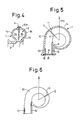
- Figure 4 shows another embodiment of the invention in which the slit 11a extends to the outer periphery of the wall 10. A portion of the periphery of the wall 10 corresponding to the position of the slit 11b in the embodiment of Figure 1 is cut away to provide a cutout 10a. The slits 11b and 11c are thus dispensed with.
- the positions of the slits 11a, 11b and 11c and the cutout 10a in the partition wall 10 are not limited to be within the angular range between the positions X and Y shown in Figure 1. They may, for instance, be formed at locations within an angular region from reference position X to position Z (see Figure 1), which is substantially midway along the scrolled or volute portion of the turbine casing and angularly spaced from the reference position X by about 60° toward the tongue B. However, the precise location and size of the slits may be varied in dependence on the size and configuration of the turbine casing.
- Figure 5 shows a further embodiment in which the slits 11a, 11b and 11c are replaced by a single slit 11 which extends radially at position Y.
- a radial slit 11 may be located at position Z as shown in Figure 6.
- the size, number and location of the slits should be selected in dependence on the thermal stresses in the partition wall 10 and at least one slit should be formed within the wide angular range between the positions Y and Z.
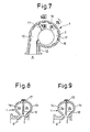
- FIGS 7 to 9 show one method of joining the partition wall 10 to the turbine casing 1.
- the partition wall 10 has a slit 11, as in the embodiment of Figure 5, and the slit 13 has been replaced by a cutout aperture in the peripheral edge at a similar position.
- the edge of the partition 10 within the turbine chamber is castellated, that is to say provided with spaced projections 17 separated by recesses or cutouts 16.
- the partition wall is joined to the turbine casing 1 at the projections 17 by welding.
- Such a method of joining the partition wall to the casing will decrease the degree of fixing or restraint of the partition wall 10 by the turbine casing 1 without any adverse effect on the secure mounting of the former and will increase the freedom of the partition wall 10 to deform, thereby resulting in a further reduction in the production of thermal stresses.
- the partition wall 10 is not welded at the gas inlet A. However, it is to be understood that it may be welded to the gas inlet A since in this case this does not unacceptably impair the ability of the partition wall 10 to expand.
Landscapes
- Engineering & Computer Science (AREA)
- Mechanical Engineering (AREA)
- General Engineering & Computer Science (AREA)
- Supercharger (AREA)
Applications Claiming Priority (4)
| Application Number | Priority Date | Filing Date | Title |
|---|---|---|---|
| JP28827/87 | 1987-03-02 | ||
| JP28828/87 | 1987-03-02 | ||
| JP2882887U JPS63138431U (fr) | 1987-03-02 | 1987-03-02 | |
| JP2882787U JPS63138430U (fr) | 1987-03-02 | 1987-03-02 |
Publications (1)
| Publication Number | Publication Date |
|---|---|
| EP0281345A1 true EP0281345A1 (fr) | 1988-09-07 |
Family
ID=26366972
Family Applications (1)
| Application Number | Title | Priority Date | Filing Date |
|---|---|---|---|
| EP88301733A Withdrawn EP0281345A1 (fr) | 1987-03-02 | 1988-02-29 | Carter de turbine pour turbocompresseur de suralimentation |
Country Status (1)
| Country | Link |
|---|---|
| EP (1) | EP0281345A1 (fr) |
Cited By (10)
| Publication number | Priority date | Publication date | Assignee | Title |
|---|---|---|---|---|
| US5399068A (en) * | 1992-07-11 | 1995-03-21 | Goldstar Co., Ltd. | Blower scroll housing with structure to reduce noise and increase air flow |
| DE10028161A1 (de) * | 2000-06-07 | 2001-12-20 | Borgwarner Inc | Turbinengehäuse für einen Abgasturbolader in Gußausführung |
| EP1500788A1 (fr) * | 2003-07-23 | 2005-01-26 | BorgWarner Inc. | Volute à double flux |
| DE102004005462A1 (de) * | 2004-02-04 | 2005-06-16 | Audi Ag | Mehrflutiges Gehäuse für eine Abgasturbine eines Abgasturboladers |
| DE102007050124A1 (de) * | 2007-10-19 | 2009-04-23 | Daimler Ag | Gehäuse für ein Laufrad |
| DE102010005492A1 (de) * | 2010-01-23 | 2011-07-28 | Bosch Mahle Turbo Systems GmbH & Co. KG, 70376 | Spiralgehäuse |
| EP2449224A1 (fr) * | 2009-06-29 | 2012-05-09 | International Engine Intellectual Property Company, LLC | Séparateur monté sur le collecteur pour admission de turbine de turbocompresseur |
| US20130108429A1 (en) * | 2011-10-31 | 2013-05-02 | Hyundai Motor Company | Turbine housing of turbocharger for vehicle |
| WO2016184617A1 (fr) * | 2015-05-21 | 2016-11-24 | Bosch Mahle Turbo Systems Gmbh & Co. Kg | Turbocompresseur à gaz d'échappement |
| WO2019037592A1 (fr) * | 2017-08-22 | 2019-02-28 | 重庆通用工业(集团)有限责任公司 | Ventilateur de tirage et équipement de transport d'air |
Citations (3)
| Publication number | Priority date | Publication date | Assignee | Title |
|---|---|---|---|---|
| FR2180411A5 (fr) * | 1972-04-13 | 1973-11-23 | Cav Ltd | |
| FR2465069A1 (fr) * | 1979-09-17 | 1981-03-20 | Ishikawajima Harima Heavy Ind | Carter de turbine pour turbocompresseur de moteur a explosion |
| EP0204509A1 (fr) * | 1985-05-29 | 1986-12-10 | Ishikawajima-Harima Jukogyo Kabushiki Kaisha | Bâche spirale pour une turbosoufflante |
-
1988
- 1988-02-29 EP EP88301733A patent/EP0281345A1/fr not_active Withdrawn
Patent Citations (3)
| Publication number | Priority date | Publication date | Assignee | Title |
|---|---|---|---|---|
| FR2180411A5 (fr) * | 1972-04-13 | 1973-11-23 | Cav Ltd | |
| FR2465069A1 (fr) * | 1979-09-17 | 1981-03-20 | Ishikawajima Harima Heavy Ind | Carter de turbine pour turbocompresseur de moteur a explosion |
| EP0204509A1 (fr) * | 1985-05-29 | 1986-12-10 | Ishikawajima-Harima Jukogyo Kabushiki Kaisha | Bâche spirale pour une turbosoufflante |
Non-Patent Citations (1)
| Title |
|---|
| PATENT ABSTRACTS OF JAPAN, vol. 10, no. 181 (M-492)[2237], 25th June 1986; & JP-A-61 028 721 (HITACHI LTD.) 08-02-1986 * |
Cited By (13)
| Publication number | Priority date | Publication date | Assignee | Title |
|---|---|---|---|---|
| US5399068A (en) * | 1992-07-11 | 1995-03-21 | Goldstar Co., Ltd. | Blower scroll housing with structure to reduce noise and increase air flow |
| DE10028161A1 (de) * | 2000-06-07 | 2001-12-20 | Borgwarner Inc | Turbinengehäuse für einen Abgasturbolader in Gußausführung |
| DE10028161C2 (de) * | 2000-06-07 | 2002-12-12 | Borgwarner Inc | Turbinengehäuse für einen Abgasturbolader in Gußausführung |
| EP1500788A1 (fr) * | 2003-07-23 | 2005-01-26 | BorgWarner Inc. | Volute à double flux |
| DE102004005462A1 (de) * | 2004-02-04 | 2005-06-16 | Audi Ag | Mehrflutiges Gehäuse für eine Abgasturbine eines Abgasturboladers |
| DE102007050124B4 (de) * | 2007-10-19 | 2010-08-12 | Daimler Ag | Gehäuse für ein Laufrad |
| DE102007050124A1 (de) * | 2007-10-19 | 2009-04-23 | Daimler Ag | Gehäuse für ein Laufrad |
| EP2449224A1 (fr) * | 2009-06-29 | 2012-05-09 | International Engine Intellectual Property Company, LLC | Séparateur monté sur le collecteur pour admission de turbine de turbocompresseur |
| EP2449224A4 (fr) * | 2009-06-29 | 2013-03-06 | Int Engine Intellectual Prop | Séparateur monté sur le collecteur pour admission de turbine de turbocompresseur |
| DE102010005492A1 (de) * | 2010-01-23 | 2011-07-28 | Bosch Mahle Turbo Systems GmbH & Co. KG, 70376 | Spiralgehäuse |
| US20130108429A1 (en) * | 2011-10-31 | 2013-05-02 | Hyundai Motor Company | Turbine housing of turbocharger for vehicle |
| WO2016184617A1 (fr) * | 2015-05-21 | 2016-11-24 | Bosch Mahle Turbo Systems Gmbh & Co. Kg | Turbocompresseur à gaz d'échappement |
| WO2019037592A1 (fr) * | 2017-08-22 | 2019-02-28 | 重庆通用工业(集团)有限责任公司 | Ventilateur de tirage et équipement de transport d'air |
Similar Documents
| Publication | Publication Date | Title |
|---|---|---|
| US6139263A (en) | Flow machine with rotor and stator | |
| US5154581A (en) | Shroud band for a rotor wheel having integral rotor blades | |
| EP0297120B1 (fr) | Joint d'etancheite inter-aubes pour rotor de turbomachine | |
| US4925365A (en) | Turbine stator ring assembly | |
| US6193465B1 (en) | Trapped insert turbine airfoil | |
| RU2338888C2 (ru) | Способ изготовления компонента статора | |
| US4378961A (en) | Case assembly for supporting stator vanes | |
| EP0717169B1 (fr) | Dispositif d'étanchéité et d'amortissement des vibrations pour la plate-forme des aubes du rotor de turbines | |
| JP4279667B2 (ja) | ターボ機械ステータハウジング | |
| RU2282727C2 (ru) | Фланец диска ротора, несущего лопатки, и его компоновка в газотурбинном двигателе | |
| US4739621A (en) | Cooling scheme for combustor vane interface | |
| TWI409383B (zh) | 燃氣渦輪機之密封件 | |
| CN110685753B (zh) | 飞行器涡轮发动机密封模块 | |
| EP0281345A1 (fr) | Carter de turbine pour turbocompresseur de suralimentation | |
| US5842831A (en) | Arrangement for the thermal protection of a rotor of a high-pressure compressor | |
| EP1225308B1 (fr) | Cartèr divisible pour une turbine à gaz | |
| US3893786A (en) | Air cooled shroud for a gas turbine engine | |
| EP1510655B1 (fr) | Support de joint à brosse | |
| JPH0713444B2 (ja) | ガスタ−ビンエンジン用ステ−タ組立体 | |
| JPH0425409B2 (fr) | ||
| CN103161511B (zh) | 静叶栅、静叶栅装配方法以及蒸汽轮机 | |
| US5961278A (en) | Housing for turbine assembly | |
| US7284955B2 (en) | Fitting of distributor sectors in an axial compressor | |
| US4451204A (en) | Aerofoil blade mounting | |
| US3751182A (en) | Guide vanes for supersonic turbine blades |
Legal Events
| Date | Code | Title | Description |
|---|---|---|---|
| PUAI | Public reference made under article 153(3) epc to a published international application that has entered the european phase |
Free format text: ORIGINAL CODE: 0009012 |
|
| AK | Designated contracting states |
Kind code of ref document: A1 Designated state(s): DE FR GB |
|
| 17P | Request for examination filed |
Effective date: 19881208 |
|
| 17Q | First examination report despatched |
Effective date: 19890412 |
|
| STAA | Information on the status of an ep patent application or granted ep patent |
Free format text: STATUS: THE APPLICATION IS DEEMED TO BE WITHDRAWN |
|
| 18D | Application deemed to be withdrawn |
Effective date: 19890822 |