EP0281237A2 - Architecture et procédé de façonnage d'un réseau rebouclé à fibres optiques - Google Patents
Architecture et procédé de façonnage d'un réseau rebouclé à fibres optiques Download PDFInfo
- Publication number
- EP0281237A2 EP0281237A2 EP88300627A EP88300627A EP0281237A2 EP 0281237 A2 EP0281237 A2 EP 0281237A2 EP 88300627 A EP88300627 A EP 88300627A EP 88300627 A EP88300627 A EP 88300627A EP 0281237 A2 EP0281237 A2 EP 0281237A2
- Authority
- EP
- European Patent Office
- Prior art keywords
- optical
- fiber
- lattice
- bus
- optical fiber
- Prior art date
- Legal status (The legal status is an assumption and is not a legal conclusion. Google has not performed a legal analysis and makes no representation as to the accuracy of the status listed.)
- Withdrawn
Links
Images
Classifications
-
- G—PHYSICS
- G01—MEASURING; TESTING
- G01D—MEASURING NOT SPECIALLY ADAPTED FOR A SPECIFIC VARIABLE; ARRANGEMENTS FOR MEASURING TWO OR MORE VARIABLES NOT COVERED IN A SINGLE OTHER SUBCLASS; TARIFF METERING APPARATUS; MEASURING OR TESTING NOT OTHERWISE PROVIDED FOR
- G01D5/00—Mechanical means for transferring the output of a sensing member; Means for converting the output of a sensing member to another variable where the form or nature of the sensing member does not constrain the means for converting; Transducers not specially adapted for a specific variable
- G01D5/26—Mechanical means for transferring the output of a sensing member; Means for converting the output of a sensing member to another variable where the form or nature of the sensing member does not constrain the means for converting; Transducers not specially adapted for a specific variable characterised by optical transfer means, i.e. using infrared, visible, or ultraviolet light
- G01D5/32—Mechanical means for transferring the output of a sensing member; Means for converting the output of a sensing member to another variable where the form or nature of the sensing member does not constrain the means for converting; Transducers not specially adapted for a specific variable characterised by optical transfer means, i.e. using infrared, visible, or ultraviolet light with attenuation or whole or partial obturation of beams of light
- G01D5/34—Mechanical means for transferring the output of a sensing member; Means for converting the output of a sensing member to another variable where the form or nature of the sensing member does not constrain the means for converting; Transducers not specially adapted for a specific variable characterised by optical transfer means, i.e. using infrared, visible, or ultraviolet light with attenuation or whole or partial obturation of beams of light the beams of light being detected by photocells
- G01D5/353—Mechanical means for transferring the output of a sensing member; Means for converting the output of a sensing member to another variable where the form or nature of the sensing member does not constrain the means for converting; Transducers not specially adapted for a specific variable characterised by optical transfer means, i.e. using infrared, visible, or ultraviolet light with attenuation or whole or partial obturation of beams of light the beams of light being detected by photocells influencing the transmission properties of an optical fibre
- G01D5/35383—Mechanical means for transferring the output of a sensing member; Means for converting the output of a sensing member to another variable where the form or nature of the sensing member does not constrain the means for converting; Transducers not specially adapted for a specific variable characterised by optical transfer means, i.e. using infrared, visible, or ultraviolet light with attenuation or whole or partial obturation of beams of light the beams of light being detected by photocells influencing the transmission properties of an optical fibre using multiple sensor devices using multiplexing techniques
-
- G—PHYSICS
- G02—OPTICS
- G02B—OPTICAL ELEMENTS, SYSTEMS OR APPARATUS
- G02B6/00—Light guides; Structural details of arrangements comprising light guides and other optical elements, e.g. couplings
- G02B6/24—Coupling light guides
- G02B6/26—Optical coupling means
- G02B6/28—Optical coupling means having data bus means, i.e. plural waveguides interconnected and providing an inherently bidirectional system by mixing and splitting signals
- G02B6/2804—Optical coupling means having data bus means, i.e. plural waveguides interconnected and providing an inherently bidirectional system by mixing and splitting signals forming multipart couplers without wavelength selective elements, e.g. "T" couplers, star couplers
- G02B6/2817—Optical coupling means having data bus means, i.e. plural waveguides interconnected and providing an inherently bidirectional system by mixing and splitting signals forming multipart couplers without wavelength selective elements, e.g. "T" couplers, star couplers using reflective elements to split or combine optical signals
-
- G—PHYSICS
- G02—OPTICS
- G02B—OPTICAL ELEMENTS, SYSTEMS OR APPARATUS
- G02B6/00—Light guides; Structural details of arrangements comprising light guides and other optical elements, e.g. couplings
- G02B6/24—Coupling light guides
- G02B6/26—Optical coupling means
- G02B6/28—Optical coupling means having data bus means, i.e. plural waveguides interconnected and providing an inherently bidirectional system by mixing and splitting signals
- G02B6/2804—Optical coupling means having data bus means, i.e. plural waveguides interconnected and providing an inherently bidirectional system by mixing and splitting signals forming multipart couplers without wavelength selective elements, e.g. "T" couplers, star couplers
- G02B6/2861—Optical coupling means having data bus means, i.e. plural waveguides interconnected and providing an inherently bidirectional system by mixing and splitting signals forming multipart couplers without wavelength selective elements, e.g. "T" couplers, star couplers using fibre optic delay lines and optical elements associated with them, e.g. for use in signal processing, e.g. filtering
-
- G—PHYSICS
- G06—COMPUTING OR CALCULATING; COUNTING
- G06E—OPTICAL COMPUTING DEVICES
- G06E3/00—Devices not provided for in group G06E1/00, e.g. for processing analogue or hybrid data
- G06E3/001—Analogue devices in which mathematical operations are carried out with the aid of optical or electro-optical elements
Definitions
- This invention relates generally to apparatus and methods for signal processing and sensing and particularly to fiber optic lattice architectures for signal processing applications and sensing changes in a physical parameter.
- An optical fiber comprises a central core and a surrounding cladding.
- the refractive index of the core is greater than that of the cladding, and the diameter of the core is so small that light guided by the core impinges upon the core-cladding interface at an angle less than the critical angle for total internal reflection.
- a light wave may be represented by a time-varying electromagnetic field comprising orthogonal electric and magnetic field vectors having a frequency equal to the frequency of the light wave.
- An electromagnetic wave propagating through a guiding structure can be described by a set of normal modes.
- the normal modes are the permissible distributions of the electric and magnetic fields within the guiding structure, for example, a fiber optic waveguide.
- the field distributions are directly related to the distribution of energy within the structure.
- the normal modes are generally represented by mathematical functions that describe the field components in the wave in terms of the frequency and spatial distribution in the guiding structure. The specific functions that describe the normal modes of a waveguide depend upon the geometry of the waveguide.
- the guided wave is confined to a structure having a circular cross section of fixed dimensions, only fields having certain frequencies and spatial distributions will propagate without severe attenuation.
- the waves having field components that propagate unattenuated are the normal modes.
- a single mode fiber will propagate only one spatial distribution of energy, that is, one normal mode, for a signal of a given frequency.
- a multimode fiber will propagate more than one normal mode of a given frequency.
- the number of guided modes in an optical fiber depends upon the diameter of the core.
- Optical fibers are useful in signal processing systems because they provide greater rates of information transfer than is possible with wires carrying electrical signals and because light signals in optical fibers provide more communications channels than lower frequency electromagnetic waves.
- Optical fiber lattice architectures have been described in the literature for signal processing applications. These lattice structures have employed symmetrical optical couplers and all single-mode optical fibers. See for example B. Moslehi, et al ., "Fiber-Optic Lattice Signal Processing," IEEE Proceedings , Vol. 72, No. 7, pp. 909-930 (1984), and K.P. Jackson, et al ., "Optical Fiber Delay Line Signal Processing," IEEE Transactions on Microwave Theory and Techniques , Vol. MTT-33, No. 3, pp. 193-210 (1985).
- a systolic system includes a set of interconnected cells that are each capable of performing some simple operation.
- the data flow is in a pipelined fashion.
- the data passes through many processing elements before leaving the system.
- Pipelining permits processing to proceed concurrently with input and output, thereby minimizing overall execution time.
- Systolic systems thus provide the advantages of effective use of data with high computation throughput, simple and regular data flows, use of simple and uniform cells, and modular expandability.
- lattice systolic multiplier structures include loops that permit recirculation of unwanted signals. See for example, United States Patent 4,588,255. Such systems require considerable time delay for recirculations or echoes from one input pulse sequence to die out before another input pulse sequence can be launched. This time delay in recirculating lattice structures limits the average duty cycle and the total data throughput of these structures.
- Optical fibers are sensitive to a large number of physical phenomena, such as acoustic waves and temperature fluctuations. Exposure to such phenomena changes the amplitude, phase or polarization of light guided by the fiber. Optical fibers have been used as sensing elements in microphones, hydrophones, magnetometers, accelerometers, electric current sensors and other devices.
- Mach-Zehnder, Michelson, Sagnac, and resonant ring interferometers have been used as sensors. Mach-Zehnder, Michelson and Sagnac interferometers respond to the phenomenon being sensed by producing phase differences in interfering light waves. Detecting phase changes in the waves permits quantitative measurements to be made on the physical quantity being monitored.
- the Sagnac interferometer produces phase differences in two counter-propagating light waves in a coil of a single fiber in response to rotations about the axis of the coil.
- a fiber optic Mach-Zehnder interferometer typically has a reference arm comprising a first length of optical fiber and a sensing arm comprising a second length of optical fiber.
- the sensing arm is exposed to the physical parameter to be measured, such as an acoustic wavefront, while the reference arm is isolated from changes in the parameter.
- acoustic wavefronts change the optical length of the sensing arm as a function of the acoustic wave pressure amplitude.
- An optical coupler divides a light signal between the two arms. The signals are recombined after they have propagated through the reference and sensing arms, and the phase difference of the signals is monitored. Since the signals in the reference and sensing arms had a definite phase relation when they were introduced into the arms, changes in the phase difference are indicative of changes in the physical parameter to which the sensing arm was exposed.
- This invention provides an improved optical fiber lattice architecture having improved efficiency, having an increased average duty cycle, and not involving recirculations of input light.
- the invention has use in fiber optic signal processing and sensing applications.
- a feed-backward fiber optic lattice structure comprises an input optical fiber bus formed of a single mode optical fiber and an output bus formed of a multimode optical fiber.
- An optical receiver receives optical signals guided by the output bus.
- a plurality of optical couplers are formed between the input optical fiber bus and the output bus. The optical couplers divide the lattice into a multiplicity of segments, and the output bus is formed into a loop around each optical coupler so that the output of any segment propagates through all the preceding segments before reaching the optical receiver.
- the feed backward fiber optic lattice structure according to the invention includes optical couplers that couple light between single mode and multimode fibers. These couplers have asymmetrical coupling efficiencies and are connected such that the amplitudes of recirculating pulses in the lattice are attenuated.
- the method of the invention for forming a feed-backward fiber optic lattice structure comprises the steps of guiding an incident optical signal on a single mode transmit optical fiber; providing a return optical fiber formed of a multimode optical fiber for guiding signals in a direction opposite to the direction of the incident signal; detecting optical signals from the return optical fiber; forming a plurality of optical couplers between the transmit and return optical fibers to divide the lattice into a multiplicity of segments; and forming a loop in the return fiber at each optical coupler so that the return signal from the m th lattice segment propagates through the first (m-1) lattice segments before impinging upon the detector.
- the method may further include the steps of forming all of the optical couplers to have asymmetrical coupling efficiencies; and connecting the couplers such that the amplitudes of recirculating pulses in the lattice are attentuated.
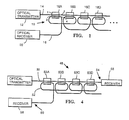
- a fiber optic lattice 10 includes an input optical fiber bus 14, an optical fiber output bus 16 and a plurality of optical couplers 18A, 18B, etc. that couple optical signals between the optical fiber buses 14 and 16.
- the input optical fiber bus 14 is formed of a single mode optical fiber
- the output bus 16 is formed of a multimode optical fiber.
- the optical transmitter 12 provides optical signals to the input optical fiber bus 14, and an optical receiver 20 receives signals guided by the output bus 16.
- the fiber 14 guides light from the input optical fiber bus 14 to port 1 of the coupler 18A. Most of the incident light remains in the fiber 14 and exits the coupler 18A at port 2. A small portion of the light incident upon the coupler 18A couples into the fiber 16 and exits the coupler 18A at port 4. The remaining input signal intensity then propagates through the input optical fiber bus 14 to port 1 of the coupler 18B. Again most of the incident light remains in the the input optical fiber bus 14 and exits the coupler 18B at port 2 for propagation to the next coupler 18C.
- All of the couplers 18A, 18B etc. may be formed to have substantially identical structures. Therefore, only the structure of the coupler 18A is described herein. This structure is also described in U.S. patent application 744,502, filed June 13, 1985.
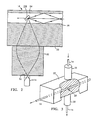
- Figures 2 and 3 show the multimode fiber 16 retained within a block 22 that may be formed of quartz.
- the multimode fiber 16 has a core 24 and a cladding 26.
- a reflector 28 is positioned on the central axis of the multimode fiber 16.
- the reflector 28 is oriented to reflect incident light so that it is nearly normal to the core/cladding interface. The reflected light therefore propagates out of the multimode fiber 16.
- the reflector 28 is very small so that only a small fraction of the light in the multimode fiber impinges upon it. Therefore, only a small fraction of the light in the multimode fiber 16 is removed therefrom by the reflector 28.
- the reflected light is directed toward a lens 30 that gathers the light removed from the multimode fiber 16 and focuses it upon an end 32 of the single mode fiber 14. Therefore, the light removed from the multimode fiber 16 is coupled into the single mode fiber 14.
- a lens 38 focuses light guided by the single mode fiber 14 toward the multimode fiber 16 onto the reflector 28.
- the reflector 28 receives a large portion of the light in the single mode fiber 14.
- the reflector 28 is arranged to reflect light into a generally cone-shaped beam directed longitudinally along the axis of the multimode fiber 16.
- the cone-shaped beam preferably diverges so that all of the modes within its acceptance cone are excited.
- the modes may be equally excited by selecting the numerical aperture of the multimode fiber 16 such that only the portion of the reflected beam having a relatively uniform intensity is within the acceptance cone.
- the coupling is then greater for light going from the single mode fiber 14 to the multimode fiber 16 than for light going from the multimode fiber 16 into the single mode fiber 14.
- the optical transmitter 12 may supply either periodically or aperiodically trains of optical pulses to the input optical fiber bus 14. These pulses preferably occur in a train at a prescribed rate and duty cycle.
- the output of the second loop in the fiber 16 propagates to the coupler 18A where moist of the signal remains in the the output bus 16 and is guided to the receiver.
- part of the signal is coupled into the the input optical fiber bus 14 as a recirculated signal.
- Part of the recirculation is coupled into the output bus 16 while part of it is transmitted to other loops in the lattice 10.
- the signals from the other loops in the lattice 10 are recirculated through all the preceding loops. The undesired terms are attenuated each time they cross couple.
- the asymmetric coupler provides greater attenuation of the unwanted recirculations than would be possible with symmetric couplers.
- the asymmetric nature of the coupling causes the fraction of the recirculated pulses to be less than the portions of the input signal that are cross coupled into the receive fiber 16. The operation of the single mode fiber to multimode fiber coupler 18A is described below.
- each mode when one unit of light power is propagating in the multimode fiber, each mode carries 1/N unit of power with a factor K of it coupled into the single-mode fiber.
- the coupling ratio from the single-mode fiber to the multimode fiber is N times that from the multimode fiber to the single-mode fiber.
- the single mode fiber to multimode fiber coupler is a nonreciprocal (asymmetric) coupler. This property provides another option for enhancing the performance of the state-of-the-art fiber processors and designing processors.
- the input signal from the the input optical fiber bus 14 may be a continuous wave optical signal.
- the input optical fiber bus 14 is a single-mode optical fiber
- the output bus 16 is a multimode optical fiber
- the couplers 18A, 18B, etc. are asymmetrical single-mode to multimode optical signal coupling devices.
- the output fiber 16 is looped backward through each of the couplers 18A, 18B, etc.
- couplers preferably have adjustable coupling ratios, but fixed ratios may be used in some applications.
- the coupling ratios of various ones of the couplers 18A, 18B, etc. are selected for the particular application for which the lattice structure is used.
- the couplers 18A, 18B, etc. may all have the same coupling ratios.
- the coupling ratios may be different.
- the array may be used for multiplying matrices.
- the operation of the lattice as a systolic multiplier is described by M. Tur, et al, "Fiber Optic Signal Processing with Applications to Matrix-Vector Multiplication and Lattice Filtering," Optic Letters , V-7, N-9, pp. 463-465, September 1982 and B. Moslehi, et al ., "Fiber-Optic Lattice Signal Processing," IEEE Proceedings , Vol. 72, No. 7, pp. 909-930 (1984).
- the lattice 10 is easier to adjust than conventional lattice structures since the coupling ratio adjustments are less interdependent. This is because the major portion of light traveling in the single-mode fiber 14 is coupled into the multimode fiber 16, whereas only a small amount of light traveling in the multimode fiber 16 is coupled back into the single-mode fiber 14. These coupling characteristics provide an increase in the average duty cycle and overall efficiency of the device.
- FIG. 4 refers to an alternate embodiment of this invention which operates in a forward flow operational mode.
- a lattice 48 comprises an input bus 50 formed of a multimode optical fiber and a receive bus 52 formed of a single-mode optical fiber. Couplers 53A, 53B, etc., couple light between the fibers 50 and 52. The output port is the end 54 of the bus 50. In this embodiment of the invention only a small amount of light is coupled from fiber 50 into fiber 52. Thus, a receiver 56 is connected to the end 54 of the fiber 50 to use the maximum available light output.
- a receiver 58 may be connected to the end 60 of fiber 52 in an application where the much lower value of output light and the differently processed light signal there has utility. Advantages of this structure are particularly related to the application of the lattice structure. Also, the optical source may be an inexpensive LED device instead of a more expensive laser diode.
- the lattice structures 10 and 48 described above may be used in systems that sense changes in a physical parameter, such as acoustic pressure.
- a long length of one of the fibers is sensitized to a particular field quantity (pressure, magnetic field, electric field, etc) and tapped periodically.
- An optical pulse of peak intensity I0 and width ⁇ seconds is injected into the transmit fiber 14 so that is propagates through the array 10, for example.
- the static phase delay arises from the time required for the pulse to propagate the quiescent length of each sensor segment.
- the dynamic phase variation arises from changes in the lengths of the segments that are exposed to variations in the field being measured.
- the data from each segment is returned as a phase modulation on each return optical pulse.
- the data from each segment is returned as a phase modulation on each return optical pulse.
- the loops in the receive fiber 16 and properly selected coupling constants cooperate to tap off a small portion of the pulse at each coupler 18A, 18B, etc.
- the tapped signals propagate to the receiver along the single receive fiber 16. The remainder of the power in the pulse continues on to the next sensitized segment.
Landscapes
- Physics & Mathematics (AREA)
- General Physics & Mathematics (AREA)
- Optics & Photonics (AREA)
- Engineering & Computer Science (AREA)
- Theoretical Computer Science (AREA)
- Mathematical Physics (AREA)
- Nonlinear Science (AREA)
- Signal Processing (AREA)
- Optical Communication System (AREA)
Applications Claiming Priority (2)
| Application Number | Priority Date | Filing Date | Title |
|---|---|---|---|
| US9967 | 1987-02-02 | ||
| US07/009,967 US4778239A (en) | 1987-02-02 | 1987-02-02 | Feed-backward lattice architecture and method |
Publications (2)
| Publication Number | Publication Date |
|---|---|
| EP0281237A2 true EP0281237A2 (fr) | 1988-09-07 |
| EP0281237A3 EP0281237A3 (fr) | 1991-12-04 |
Family
ID=21740757
Family Applications (1)
| Application Number | Title | Priority Date | Filing Date |
|---|---|---|---|
| EP19880300627 Withdrawn EP0281237A3 (fr) | 1987-02-02 | 1988-01-26 | Architecture et procédé de façonnage d'un réseau rebouclé à fibres optiques |
Country Status (2)
| Country | Link |
|---|---|
| US (1) | US4778239A (fr) |
| EP (1) | EP0281237A3 (fr) |
Cited By (1)
| Publication number | Priority date | Publication date | Assignee | Title |
|---|---|---|---|---|
| FR2758194A1 (fr) * | 1997-01-09 | 1998-07-10 | Jean Lecaroz | Ordinateur neuro-mimetique forme d'un reseau tridimensionnel incluant des corps a changement d'etat interconnectes |
Families Citing this family (11)
| Publication number | Priority date | Publication date | Assignee | Title |
|---|---|---|---|---|
| US4871225A (en) * | 1984-08-24 | 1989-10-03 | Pacific Bell | Fiber optic distribution network |
| FR2630833B1 (fr) * | 1988-04-27 | 1992-02-28 | Organisation Europ Rech Nucle | Dispositif pour stocker des photons et appareillage de determination de la forme d'une impulsion lumineuse de breve duree en faisant application |
| AU613497B2 (en) * | 1988-05-12 | 1991-08-01 | Commonwealth of Australia of Department of Defence, The | An interferometric fibre optic network |
| US4961621A (en) * | 1988-12-22 | 1990-10-09 | Gte Laboratories, Inc. | Optical parallel-to-serial converter |
| US4934777A (en) * | 1989-03-21 | 1990-06-19 | Pco, Inc. | Cascaded recirculating transmission line without bending loss limitations |
| GB2233109B (en) * | 1989-06-13 | 1993-05-12 | Plessey Co Plc | Optical fibre lattice signal processors |
| JP3085311B2 (ja) * | 1990-05-25 | 2000-09-04 | 日本電信電話株式会社 | Fifoバッファ |
| US5191627A (en) * | 1990-09-24 | 1993-03-02 | International Business Machines Corporation | Reduction of intersymbol interference in optical fiber systems by wavelength filtering |
| US5600470A (en) * | 1993-06-21 | 1997-02-04 | Hewlett-Packard Co | Mixed fiber adapter cable |
| US6081633A (en) * | 1995-11-03 | 2000-06-27 | The United States Of America As Represented By The Secretary Of The Navy | Fiber optic sensor array system with forward coupled topology |
| GB9709627D0 (en) * | 1997-05-13 | 1997-07-02 | Hewlett Packard Co | Multimode communications systems |
Family Cites Families (40)
| Publication number | Priority date | Publication date | Assignee | Title |
|---|---|---|---|---|
| US3645603A (en) * | 1969-09-24 | 1972-02-29 | Luther W Smith | Light modulation in optic fiber |
| US3990036A (en) * | 1974-02-28 | 1976-11-02 | Western Geophysical Co. | Multiplexing method and apparatus for telemetry of seismic data |
| GB1534786A (en) * | 1976-06-29 | 1978-12-06 | Standard Telephones Cables Ltd | Data transmission system |
| AU4223778A (en) * | 1977-12-12 | 1979-06-21 | Pedro B Macedo | Optical waveguide sensor |
| US4307937A (en) * | 1979-06-04 | 1981-12-29 | Northern Telecom Limited | Optical modulators |
| JPS5621004A (en) * | 1979-07-30 | 1981-02-27 | Toshiba Corp | Optical sensing system |
| CA1124384A (fr) * | 1979-08-09 | 1982-05-25 | Paolo G. Cielo | Hydrophone a fibre optique stable |
| US4294513A (en) * | 1979-09-11 | 1981-10-13 | Hydroacoustics Inc. | Optical sensor system |
| DE2938810A1 (de) * | 1979-09-25 | 1981-04-09 | Siemens AG, 1000 Berlin und 8000 München | Vorrichtung zum einkoppeln von strahlung in einen optischen wellenleiter |
| FR2473188A1 (fr) * | 1980-01-04 | 1981-07-10 | Transmissions Optiq Cie Lyonna | Te optique bi-directionnel |
| US4443700A (en) * | 1980-02-01 | 1984-04-17 | Pedro B. Macedo | Optical sensing apparatus and method |
| US4301543A (en) * | 1980-02-20 | 1981-11-17 | General Dynamics Corporation, Pomona Division | Fiber optic transceiver and full duplex point-to-point data link |
| US4307933A (en) * | 1980-02-20 | 1981-12-29 | General Dynamics, Pomona Division | Optical fiber launch coupler |
| US4360272A (en) * | 1980-03-20 | 1982-11-23 | Optelecom, Inc. | Fiber optic energy sensor and optical demodulation system and methods of making same |
| US4493528A (en) * | 1980-04-11 | 1985-01-15 | Board Of Trustees Of The Leland Stanford Junior University | Fiber optic directional coupler |
| CA1143978A (fr) * | 1980-11-26 | 1983-04-05 | Derwyn C. Johnson | Configurations de bus de donnees a fibres optiques |
| GB2096762A (en) * | 1981-04-09 | 1982-10-20 | Univ London | Optical fibre sensor device |
| DE3224775A1 (de) * | 1981-06-30 | 1983-01-20 | Hahn-Meitner-Institut für Kernforschung Berlin GmbH, 1000 Berlin | Ueberwachungssystem fuer betriebsanlagen |
| US4505587A (en) * | 1981-08-14 | 1985-03-19 | Massachusetts Institute Of Technology | Picosecond optical sampling |
| US4588296A (en) * | 1981-10-07 | 1986-05-13 | Mcdonnell Douglas Corporation | Compact optical gyro |
| US4418981A (en) * | 1982-01-19 | 1983-12-06 | Gould Inc. | Quadrature fiber-optic interferometer matrix |
| US4514054A (en) * | 1982-01-19 | 1985-04-30 | Gould Inc. | Quadrature fiber-optic interferometer matrix |
| US4490163A (en) * | 1982-03-22 | 1984-12-25 | U.S. Philips Corporation | Method of manufacturing a fiber-optical coupling element |
| ATE48033T1 (de) * | 1982-04-14 | 1989-12-15 | Univ Leland Stanford Junior | Fiber-optischer sensor zum detektieren sehr kleiner verschiebungen einer oberflaeche. |
| JPS58211119A (ja) * | 1982-06-01 | 1983-12-08 | Nec Corp | バス伝送用光結合器 |
| US4588255A (en) * | 1982-06-21 | 1986-05-13 | The Board Of Trustees Of The Leland Stanford Junior University | Optical guided wave signal processor for matrix-vector multiplication and filtering |
| US4530603A (en) * | 1982-09-29 | 1985-07-23 | The Board Of Trustees Of Leland Stanford Jr. Univ. | Stabilized fiber optic sensor |
| DE3280135D1 (de) * | 1982-11-12 | 1990-04-19 | Univ Leland Stanford Junior | Kontinuierlich einstellbare faseroptikverzoegerungslinie. |
| US4552457A (en) * | 1983-02-01 | 1985-11-12 | Giallorenzi Thomas G | Fiber optic interferometer using two wavelengths or variable wavelength |
| US4697876A (en) * | 1983-02-25 | 1987-10-06 | Andrew Corporation | Fiber-optic rotation sensor |
| US4545253A (en) * | 1983-08-29 | 1985-10-08 | Exxon Production Research Co. | Fiber optical modulator and data multiplexer |
| US4606020A (en) * | 1984-02-03 | 1986-08-12 | The United States Of America As Represented By The Secretary Of The Army | Efficient design technique for wavelength division multiplexing |
| US4630885A (en) * | 1984-03-02 | 1986-12-23 | Northrop Corporation | Multichannel optical wave guide resonator |
| US4633170A (en) * | 1984-06-05 | 1986-12-30 | The United States Of America As Represented By The Secretary Of The Navy | Bragg cell spectrum analyzer |
| US4632551A (en) * | 1984-06-11 | 1986-12-30 | Litton Systems, Inc. | Passive sampling interferometric sensor arrays |
| US4676583A (en) * | 1984-06-28 | 1987-06-30 | Polaroid Corporation | Adscititious resonator |
| GB2166020B (en) * | 1984-09-29 | 1988-05-18 | Plessey Co Plc | Otdr-uses multiple frequencies to detect distortions in an optical fibre |
| US4648083A (en) * | 1985-01-03 | 1987-03-03 | The United States Of America As Represented By The Secretary Of The Navy | All-optical towed and conformal arrays |
| US4697926A (en) * | 1985-02-08 | 1987-10-06 | The Board Of Trustees Of The Leland Stanford Junior University | Coherent distributed sensor and method using short coherence length sources |
| US4648082A (en) * | 1985-03-04 | 1987-03-03 | Western Geophysical Company Of America | Marine acoustic gradient sensor |
-
1987
- 1987-02-02 US US07/009,967 patent/US4778239A/en not_active Expired - Fee Related
-
1988
- 1988-01-26 EP EP19880300627 patent/EP0281237A3/fr not_active Withdrawn
Cited By (2)
| Publication number | Priority date | Publication date | Assignee | Title |
|---|---|---|---|---|
| FR2758194A1 (fr) * | 1997-01-09 | 1998-07-10 | Jean Lecaroz | Ordinateur neuro-mimetique forme d'un reseau tridimensionnel incluant des corps a changement d'etat interconnectes |
| WO1998030946A1 (fr) * | 1997-01-09 | 1998-07-16 | Jean Lecaroz | Ordinateur neuro-mimetique a configuration variable qui peut fonctionner comme un ordinateur quantique |
Also Published As
| Publication number | Publication date |
|---|---|
| EP0281237A3 (fr) | 1991-12-04 |
| US4778239A (en) | 1988-10-18 |
Similar Documents
| Publication | Publication Date | Title |
|---|---|---|
| US4784453A (en) | Backward-flow ladder architecture and method | |
| US4775216A (en) | Fiber optic sensor array and method | |
| US4699513A (en) | Distributed sensor and method using coherence multiplexing of fiber-optic interferometric sensors | |
| US4632551A (en) | Passive sampling interferometric sensor arrays | |
| US4697926A (en) | Coherent distributed sensor and method using short coherence length sources | |
| CA1213990A (fr) | Modulateur et multiplexeur de donnees a fibre optique | |
| US4515430A (en) | Integrated optical transducers | |
| US4238856A (en) | Fiber-optic acoustic sensor | |
| US4479701A (en) | Dual coupler fiber optic recirculating memory | |
| CA1320356C (fr) | Capteur a fibre optique a multiplexage | |
| US4511207A (en) | Fiber optic data distributor | |
| US4778239A (en) | Feed-backward lattice architecture and method | |
| US4752132A (en) | Low power control interferometric sensor with wide dynamic range | |
| JPH0220083B2 (fr) | ||
| US4777661A (en) | Apparatus and method for self-referencing and multiplexing intensity modulating fiber optic sensors | |
| US4768880A (en) | System and method for accurate loop length determination in fiber-optic sensors and signal processors | |
| EP1010024B1 (fr) | Element optique | |
| JP2001503140A (ja) | 偏光維持ファイバを有するセンサ装置 | |
| GB2147759A (en) | Optical sensor | |
| US5486921A (en) | Optimum coupler configuration for fiber optic rate gyroscope using [3×] coupler | |
| AU2010306071B2 (en) | Modalmetric fibre sensor | |
| RU2060597C1 (ru) | Оптико-волоконный гидрофон | |
| SU1744676A1 (ru) | Волоконно-оптический преобразователь | |
| JPS61117411A (ja) | 光フアイバセンサ | |
| SU1620818A1 (ru) | Многофункциональный интерферометрический оптоволоконный преобразователь |
Legal Events
| Date | Code | Title | Description |
|---|---|---|---|
| PUAI | Public reference made under article 153(3) epc to a published international application that has entered the european phase |
Free format text: ORIGINAL CODE: 0009012 |
|
| AK | Designated contracting states |
Kind code of ref document: A2 Designated state(s): FR GB |
|
| PUAL | Search report despatched |
Free format text: ORIGINAL CODE: 0009013 |
|
| AK | Designated contracting states |
Kind code of ref document: A3 Designated state(s): FR GB |
|
| STAA | Information on the status of an ep patent application or granted ep patent |
Free format text: STATUS: THE APPLICATION IS DEEMED TO BE WITHDRAWN |
|
| 18D | Application deemed to be withdrawn |
Effective date: 19920605 |