EP0281020A2 - Device for the wet purification of gas, constructed in module type - Google Patents
Device for the wet purification of gas, constructed in module type Download PDFInfo
- Publication number
- EP0281020A2 EP0281020A2 EP88102831A EP88102831A EP0281020A2 EP 0281020 A2 EP0281020 A2 EP 0281020A2 EP 88102831 A EP88102831 A EP 88102831A EP 88102831 A EP88102831 A EP 88102831A EP 0281020 A2 EP0281020 A2 EP 0281020A2
- Authority
- EP
- European Patent Office
- Prior art keywords
- gas
- washing unit
- foam
- washing
- module
- Prior art date
- Legal status (The legal status is an assumption and is not a legal conclusion. Google has not performed a legal analysis and makes no representation as to the accuracy of the status listed.)
- Withdrawn
Links
Images

Classifications
-
- B—PERFORMING OPERATIONS; TRANSPORTING
- B01—PHYSICAL OR CHEMICAL PROCESSES OR APPARATUS IN GENERAL
- B01D—SEPARATION
- B01D47/00—Separating dispersed particles from gases, air or vapours by liquid as separating agent
- B01D47/04—Separating dispersed particles from gases, air or vapours by liquid as separating agent by passing the gas or air or vapour through foam
-
- B—PERFORMING OPERATIONS; TRANSPORTING
- B01—PHYSICAL OR CHEMICAL PROCESSES OR APPARATUS IN GENERAL
- B01D—SEPARATION
- B01D47/00—Separating dispersed particles from gases, air or vapours by liquid as separating agent
- B01D47/06—Spray cleaning
-
- B—PERFORMING OPERATIONS; TRANSPORTING
- B01—PHYSICAL OR CHEMICAL PROCESSES OR APPARATUS IN GENERAL
- B01D—SEPARATION
- B01D47/00—Separating dispersed particles from gases, air or vapours by liquid as separating agent
- B01D47/12—Washers with plural different washing sections
-
- B—PERFORMING OPERATIONS; TRANSPORTING
- B01—PHYSICAL OR CHEMICAL PROCESSES OR APPARATUS IN GENERAL
- B01D—SEPARATION
- B01D50/00—Combinations of methods or devices for separating particles from gases or vapours
- B01D50/40—Combinations of devices covered by groups B01D45/00 and B01D47/00
Definitions
- the invention relates to a modular design device for the wet cleaning of gas with a horizontal body, the gas inlet side at least one gas washing unit built as a module with tubes arranged transversely to the flow direction of the gas, with a sprinkler provided for the washing liquid and with one among the pipes Pipe attached adjustable distributor for the gas is assigned, and the gas outlet side has a separator built as a module with drip catcher.
- the tubes of the gas scrubbing unit form spaces which act as Venturi nozzles and which cause a suction effect.
- a trough with a device for removing sludge is provided on the bottom of the body.
- corrugated surfaces, nets or other elements can also be provided in the washing unit designed as a module.
- the object underlying the invention is therefore to design the device of the generic type so that the gas can be optimally cleaned in successive, coordinated stages.
- a foam washing unit which is arranged in the horizontal body in the flow direction of the gas after the gas washing unit and is also constructed as a module and which has a grid floor, a foam stabilizer and spray nozzles arranged above it, and by one below arranged the foam washing unit, this connecting to the gas washing unit, formed by a front wall and side walls of the horizontal body and a collector inclined downward towards the gas washing unit, wherein at the deepest point of the inclined bottom a transverse conical drainage channel with washing nozzle is provided.
- module units in a horizontal arrangement depending on the physico-chemical parameters of the gases to be cleaned that pass through them Integrate gas cleaning line with successive module washing zones, in a common horizontal body, which makes maintenance and operation very easy and the material required for production is relatively low.
- the modular construction device shown in FIG. 1 for the wet cleaning of gas consists of a horizontal body 1 which has side walls 2, an end wall 3, observation windows 4, 5 and 6, a cover 7 and an outlet opening 8.
- the horizontal body 1 is preceded by a gas scrubbing unit 13 designed as a module in the form of a cassette.
- a gas scrubbing unit 13 designed as a module in the form of a cassette.
- a set of parallel tubes 10 is arranged, which form spaces acting between them as Venturi nozzles when the flow is transverse.
- a device 11 for sprinkling with a washing liquid is provided above the pipes 10, which device can consist, for example, of a distributor having nozzles.
- the gas washing unit 13 has an upper inlet 9 into which the gas to be cleaned, illustrated by the arrows 27, flows in crosswise direction to the tubes 10 and in cocurrent with the washing liquid.
- An adjustable distributor 14 for the gas is arranged under the tubes 10 of the gas washing unit 13.
- a modular separator 15 is provided on the outlet side and has a drip catcher 16.
- a foam washing unit 17 designed as a module, which consists of a trough 18 with a grid floor 19 and has a foam stabilizer 20 with nozzles 21 arranged above it.
- the foam washing unit 17 is arranged above a bottom 22 which is inclined downward toward the gas washing unit 13 and which, together with the end wall 3 and the side walls 2 of the horizontal body 1, forms a collector 23 which connects the gas washing unit 13 to the foam washing unit 17 and orientates it towards it is.
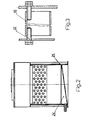
- a transverse conical drain channel 24 is provided, as can be seen from FIG. 2.
- a washing nozzle 25 is provided for the periodic or constant cleaning of the drain channel 24.
- the washing liquid generally water, which flows out of the nozzles of the sprinkler 11 or the nozzles 21 above the foam stabilizer 20, fills the lower part of the horizontal body 1 to form a liquid seal 26.
- the gas to be cleaned supplied in the direction of the arrows 27 passes through the inlet 9 of the gas scrubbing unit 13 together with the scrubbing liquid discharged from the sprinkling device 11 into the spaces between the tubes 10, which act dynamically like Venturi nozzles due to the cross flow of the tubes, which leads to gas suction and contributes to the good mixing of the contaminated gas with the washing liquid.
- the dust particles in the gas to be cleaned are brought into intimate and direct contact on a large surface. As the gas exits the spaces between the tubes 10, its pressure increases and its speed slows down, causing most of the wetted dust particles to agglomerate and to settle on the surface of the liquid closure 26, which consists of washing liquid.
- the gas with the remaining dust particles and impurities is fed through the adjustable distributor 14 and the collector 23 inclined upward towards the foam washing unit 17 to this unit 17, which is designed as a module.
- the agglomeration of some of the dust particles in the gas washing unit 13 prepares the physico-chemical parameters of the gas for the subsequent highly effective cleaning in the foam washing unit 17, which is also designed as a module, this cleaning taking place with an optimal consumption of washing liquid and energy. Due to the dynamic conditions in the venturi spaces between the tubes 10, evaporation processes occur in the hot gases to be cleaned, which leads to a temperature drop to a desired possible limit, which is the prerequisite for a subsequent forced condensation and an effective separation of the residual dust from the gas stream in the foam washing unit 17 built as a module.
- the gas to be cleaned flows from bottom to top through the grid bottom 19 of the tub 18, while washing liquid flows through the nozzles 21 from top to bottom through the grid bottom 19 of the tub 18.
- a layer of movable foam is formed, which is maintained by the foam stabilizer 20.
- the foam stabilizer 20 ensures stable hydrodynamic conditions and thereby influences the state of the movable foam layer very much, a limitation resulting only from the large number of droplets being carried away.
- the cleaned gas emerges from the foam washing unit 17, it flows out through the drip catcher 16 of the separator 15, which is constructed in a modular design, and through the outlet opening 8.
- a pre-cleaning of the gas is achieved by the gas washing unit 13, which enables optimum post-cleaning in the downstream foam washing unit 17 built from a module.
Abstract
Description
Die Erfindung betrifft eine in Modulbauweise ausgeführte Vorrichtung für die Naßreinigung von Gas mit einem horizontalen Körper, dem gaseinlaßseitig wenigstens eine als Modul gebaute Gaswascheinheit mit quer zur Strömungsrichtung des Gases angeordneten Rohren, mit einer über den Rohren vorgesehenen Berieselungseinrichtung für eine Waschflüssigkeit und mit einem unter den Rohren angebrachten einstellbaren Verteiler für das Gas zugeordnet ist, und der gasauslaßseitig einen als Modul gebauten Separator mit Tropfenfänger aufweist.The invention relates to a modular design device for the wet cleaning of gas with a horizontal body, the gas inlet side at least one gas washing unit built as a module with tubes arranged transversely to the flow direction of the gas, with a sprinkler provided for the washing liquid and with one among the pipes Pipe attached adjustable distributor for the gas is assigned, and the gas outlet side has a separator built as a module with drip catcher.
Bei einer solchen, aus der US-PS 381 1252 bekannten Vorrichtung bilden die Rohre der Gaswascheinheit als Venturidüsen wirkende Räume, die eine Ansaugwirkung hervorrufen. Bodenseitig ist an dem Körper eine Wanne mit einer Einrichtung zur Schlammbeseitigung vorgesehen. Anstatt der Rohre können in der als Modul ausgebildeten Wascheinheit auch geriffelte Flächen, Netze oder andere Elemente vorgesehen werden.In such a device known from US-PS 381 1252, the tubes of the gas scrubbing unit form spaces which act as Venturi nozzles and which cause a suction effect. A trough with a device for removing sludge is provided on the bottom of the body. Instead of the tubes, corrugated surfaces, nets or other elements can also be provided in the washing unit designed as a module.
Bei der bekannten Vorrichtung ist nur die Zuordnung einer einzigen als Modul ausgebildeten Wascheinheit möglich, so daß eine gezielte Gasreinigung im Hinblick auf spezielle physikalisch-chemische Parameter nicht möglich ist. Außerdem ist bei stark verschmutzten Abgasen die Reinigungswirkung unzureichend.In the known device, it is only possible to assign a single washing unit designed as a module, so that targeted gas cleaning is not possible with regard to special physico-chemical parameters. In addition, the cleaning effect is insufficient for heavily polluted exhaust gases.
Die der Erfindung zugrunde liegende Aufgabe besteht deshalb darin, die Vorrichtung der gattungsgemäßen Art so zu gestalten, daß das Gas in aufeinanderfolgenden, aufeinander abgestimmten Stufen optimal gereinigt werden kann.The object underlying the invention is therefore to design the device of the generic type so that the gas can be optimally cleaned in successive, coordinated stages.
Diese Aufgabe wird ausgehend von der in Modulbauweise ausgeführten Vorrichtung der gattungsgemäßen Art durch eine in dem horizontalen Körper in Strömungsrichtung des Gases nach der Gaswascheinheit angeordnete, ebenfalls als Modul gebaute Schaumwascheinheit, welche einen Gitterboden, einen Schaumstabilisator und darüber angeordnete Sprühdüsen aufweist, und durch einen unterhalb der Schaumwascheinheit angeordneten, diese mit der Gaswascheinheit verbindenden, von einer Stirnwand und Seitenwänden des horizontalen Körpers sowie einem zur Gaswascheinheit nach unten geneigten Boden gebildeten Kollektor gelöst, wobei an der tiefsten Stelle des geneigten Bodens ein transversaler kegelförmiger Ablaufkanal mit Waschstutzen vorgesehen ist.This object is achieved on the basis of the modular construction device of the generic type by a foam washing unit which is arranged in the horizontal body in the flow direction of the gas after the gas washing unit and is also constructed as a module and which has a grid floor, a foam stabilizer and spray nozzles arranged above it, and by one below arranged the foam washing unit, this connecting to the gas washing unit, formed by a front wall and side walls of the horizontal body and a collector inclined downward towards the gas washing unit, wherein at the deepest point of the inclined bottom a transverse conical drainage channel with washing nozzle is provided.
Mit der erfindungsgemäßen Vorrichtung ist es möglich, in horizontaler Anordnung Moduleinheiten abhängig von den physikalisch-chemischen Parametern der durch sie hindurchgehenden zu reinigenden Gase zu einer gesteuerten Gasreinigungsstraße mit aufeinanderfolgenden Modulwaschzonen zu integrieren, und zwar in einem gemeinsamen horizontalen Körper, wodurch Wartung und Betrieb sehr einfach und der für die Herstellung erforderliche Materialeinsatz relativ gering sind.With the device according to the invention, it is possible to arrange module units in a horizontal arrangement depending on the physico-chemical parameters of the gases to be cleaned that pass through them Integrate gas cleaning line with successive module washing zones, in a common horizontal body, which makes maintenance and operation very easy and the material required for production is relatively low.
Anhand von Zeichnungen wird ein Ausführungsbeispiel der Erfindung näher erläutert. Es zeigt:
- Fig. 1 einen Längsschnitt durch die Vorrichtung,
- Fig. 2 den Schnitt A-A von Fig. 1 und
- Fig. 3 im Schnitt B-B von Fig. 1 die Aufhängung der Rohre in der Gaswascheinheit.
- 1 shows a longitudinal section through the device,
- Fig. 2 shows the section AA of Fig. 1 and
- Fig. 3 in section BB of Fig. 1, the suspension of the pipes in the gas washing unit.
Die in Fig. 1 gezeigte, in Modulbauweise ausgeführte Vorrichtung für die Naßreinigung von Gas besteht aus einem horizontalen Körper 1, der Seitenwände 2, eine Stirnwand 3, Beobachtungsfenster 4, 5 und 6, einen Deckel 7 sowie eine Auslaßöffnung 8 aufweist. Dem horizontalen Körper 1 ist einlaßseitig eine als Modul in Form einer Kassette ausgebildete Gaswascheinheit 13 vorgeordnet. In der Gaswascheinheit 13 ist ein Satz von parallelen Rohren 10 angeordnet, die bei Queranströmung zwischen sich als Venturidüsen wirkende Räume bilden. Über den Rohren 10 ist eine Einrichtung 11 zur Berieselung mit einer Waschflüssigkeit vorgesehen, die beispielsweise aus einem Düsen aufweisenden Verteiler bestehen kann.The modular construction device shown in FIG. 1 for the wet cleaning of gas consists of a horizontal body 1 which has side walls 2, an end wall 3,
Wie aus Fig. 3 zu ersehen ist, sind die Rohre 10 frei auf Verbindungsbolzen 12 aufgehängt.As can be seen from Fig. 3, the
Die Gaswascheinheit 13 hat einen oberen Einlaß 9, in den das durch die Pfeile 27 veranschaulichte, zu reinigende Gas quer zu den Rohren 10 und im Gleichstrom mit der Waschflüssigkeit einströmt. Unter den Rohren 10 der Gaswascheinheit 13 ist ein einstellbar Verteiler 14 für das Gas angeordnet.The
In dem horizontaler Körper 1 ist auslaßseitig ein in Modulbauweise ausgeführter Separator bzw. Abscheider 15 vorgesehen, der einen Tropfenfänger 16 aufweist. Zwischen der Gaswascheinheit 13 und dem Separator 15 ist eine als Modul ausgeführte Schaumwascheinheit 17 angeordnet, die aus einer Wanne 18 mit einem Gitterboden 19 besteht und einen Schaumstabilisator 20 mit darüber angeordneten Düsen 21 aufweist. Die Schaumwascheinheit 17 ist oberhalb eines zur Gaswascheinheit 13 hin nach unten geneigten Bodens 22 angeordnet, der zusammen mit der Stirnwand 3 und den Seitenwänden 2 des horizontalen Körpers 1 einen Kollektor 23 bildet, der die Gaswascheinheit 13 mit der Schaumwascheinheit 17 verbindet und zu dieser hin orientiert ist. Im tiefsten Teil des geneigten Kollektors 23 ist ein transversaler kegelförmiger Ablaufkanal 24 vorgesehen, wie dies aus Fig. 2 zu ersehen ist. Für die periodische oder ständige Reinigung des Ablaufkanals 24 ist ein Waschstuzten 25 vorgesehen. Die Waschflüssigkeit, im allgemeinen Wasser, die aus den Düsen der Berieselungseinrichtung 11 oder den Düsen 21 über dem Schaumstabilisator 20 ausströmt, füllt den unteren Teil des horizontalen Körpers 1 unter Bildung eines Flüssigkeitsverschlusses 26.In the horizontal body 1, a
Das in Richtung der Pfeile 27 zugeführte zu reinigende Gas gelangt durch den Einlaß 9 der Gaswascheinheit 13 zusammen mit der aus der Berieselungseinrichtung 11 abgegebenen Waschflüssigkeit in die Zwischenräume zwischen den Rohren 10, die aufgrund der Queranströmung der Rohre dynamisch wie Venturidüsen wirken, was zur Gasansaugung und zur guten Vermischung des verunreinigten Gases mit der Waschflüssigkeit beiträgt. Dabei werden die in dem zu reinigenden Gas vorhandenen Staubteilchen in innigen und direkten Kontakt auf einer großen Oberfläche gebracht. Wenn das Gas aus den Zwischenräumen zwischen den Rohren 10 austritt, erhöht sich sein Druck und verzögert sich seine Geschwindigkeit, wodurch die meisten der befeuchteten Staubteilchen agglomerieren und sich auf der Oberfläche des aus Waschflüssigkeit bestehenden Flüssigkeitsverschlusses 26 absetzen. Das Gas mit den restlichen Staubteilchen und Verunreinigungen wird durch den einstellbaren Verteiler 14 und den zur Schaumwascheinheit 17 nach oben geneigten Kollektor 23 zu dieser als Modul ausgeführten Einheit 17 gefürt. Auf diese Weise bereit die Agglomerierung eines Teils der Staubteilchen in der Gaswascheinheit 13 die physikalisch-chemischen Parameter des Gases für die darauffolgende hochwirksame Reinigung in der ebenfalls als Modul ausgeführten Schaumwascheinheit 17 vor, wobei diese Reinigungs mit einem optimalen Verbrauch an Waschflüssigkeit und Energie erfolgt. Aufgrund der dynamischen Bedingungen in den Venturizwischenräumen zwischen den Rohren 10 ergeben sich bei den zugeführten zu reinigenden warmen Gasen Verdampfungsprozesse, was zu einer Temperaturabsenkung bis zu einer gewünschten möglichen Grenze führt, die die Voraussetzung für eine nachfolgende Zwangskondensation und eine wirksame Trennung des Reststaubs von dem Gasstrom in der als Modul gebauten Schaumwascheinheit 17 ist.The gas to be cleaned supplied in the direction of the
In der Schaumwascheinheit 17 strömt das zu reinigende Gas von unten nach oben durch den Gitterboden 19 der Wanne 18, während durch die Düsen 21 Waschflüssigkeit von oben nach unten durch den Gitterboden 19 der Wanne 18 strömt. Infolge der dadurch bedingten Wechselwirkung der beiden Phasen, nämlich Flüssigkeit und Gas, wird eine Schicht aus beweglichem Schaum gebildet, die durch den Schaumstabilisator 20 aufrechterhalten wird. Der Schaumstabilisator 20 sorgt für stabile hydrodynamische Bedingungen und beeinflußt dadurch den Zustand der beweglichen Schaumschicht sehr, wobei sich eine Beschränkung nur aufgrund der vielen mit fortgerissenen Tropfen ergibt. Nach dem Austritt des gereinigten Gases aus der Schaumwascheinheit 17 strömt es durch den Tropfenfänger 16 des in Modulbauweise ausgeführten Separators 15 und durch die Auslaßöffnung 8 ab. Durch die Gaswascheinheit 13 wird eine Vorreinigung des Gases erreicht, die eine optimale Nachreinigung in der nachgeschalteten, aus Modul gebauten Schaumwascheinheit 17, ermöglicht.In the
Claims (1)
Applications Claiming Priority (2)
| Application Number | Priority Date | Filing Date | Title |
|---|---|---|---|
| BG8778638A BG44904A1 (en) | 1987-02-25 | 1987-02-25 | |
| BG78638/87 | 1987-02-25 |
Publications (2)
| Publication Number | Publication Date |
|---|---|
| EP0281020A2 true EP0281020A2 (en) | 1988-09-07 |
| EP0281020A3 EP0281020A3 (en) | 1989-09-06 |
Family
ID=3918614
Family Applications (1)
| Application Number | Title | Priority Date | Filing Date |
|---|---|---|---|
| EP88102831A Withdrawn EP0281020A3 (en) | 1987-02-25 | 1988-02-25 | Device for the wet purification of gas, constructed in module type |
Country Status (2)
| Country | Link |
|---|---|
| EP (1) | EP0281020A3 (en) |
| BG (1) | BG44904A1 (en) |
Cited By (3)
| Publication number | Priority date | Publication date | Assignee | Title |
|---|---|---|---|---|
| EP0641242A1 (en) * | 1992-05-19 | 1995-03-08 | MAI, Sung-Chuan | Filter system for smoke or polluted air |
| CN110639680A (en) * | 2019-08-24 | 2020-01-03 | 安徽友邦新材料有限公司 | Limestone screening device |
| CN113559646A (en) * | 2021-09-24 | 2021-10-29 | 徐州众迈节能环保科技有限公司 | Medium-catching self-falling type organic waste gas two-stage separation device |
Citations (7)
| Publication number | Priority date | Publication date | Assignee | Title |
|---|---|---|---|---|
| DE1471634B1 (en) * | 1963-10-08 | 1969-10-16 | Waagner Biro Ag | Device for separating impurities finely divided in gases |
| DE2231895A1 (en) * | 1971-07-20 | 1973-02-08 | Environeering | Gas scrubbing - removes by diffusion into froth particles below 1/4000 mm |
| CH561077A5 (en) * | 1973-10-18 | 1975-04-30 | Capuli Giuseppe | Exhaust fume scrubber - to remove soot and impurities from gas passed through tank of liq via a conical constriction |
| DE2917749A1 (en) * | 1978-05-04 | 1979-11-15 | Kureha Chemical Ind Co Ltd | GAS-LIQUID CONTACT DEVICE |
| DE3031951A1 (en) * | 1979-08-29 | 1981-03-26 | Ciba-Geigy Ag, Basel | SYSTEM FOR THE REMOVAL OF GASEOUS AND SOLID POLLUTANTS AND MIST FROM AN EXHAUST GAS |
| US4263024A (en) * | 1979-10-10 | 1981-04-21 | Venturmation, Inc. | Air cleaning device |
| US4608064A (en) * | 1985-01-03 | 1986-08-26 | Protectaire Systems Co. | Multi-wash spray booth and method of capturing air borne particles |
-
1987
- 1987-02-25 BG BG8778638A patent/BG44904A1/xx unknown
-
1988
- 1988-02-25 EP EP88102831A patent/EP0281020A3/en not_active Withdrawn
Patent Citations (7)
| Publication number | Priority date | Publication date | Assignee | Title |
|---|---|---|---|---|
| DE1471634B1 (en) * | 1963-10-08 | 1969-10-16 | Waagner Biro Ag | Device for separating impurities finely divided in gases |
| DE2231895A1 (en) * | 1971-07-20 | 1973-02-08 | Environeering | Gas scrubbing - removes by diffusion into froth particles below 1/4000 mm |
| CH561077A5 (en) * | 1973-10-18 | 1975-04-30 | Capuli Giuseppe | Exhaust fume scrubber - to remove soot and impurities from gas passed through tank of liq via a conical constriction |
| DE2917749A1 (en) * | 1978-05-04 | 1979-11-15 | Kureha Chemical Ind Co Ltd | GAS-LIQUID CONTACT DEVICE |
| DE3031951A1 (en) * | 1979-08-29 | 1981-03-26 | Ciba-Geigy Ag, Basel | SYSTEM FOR THE REMOVAL OF GASEOUS AND SOLID POLLUTANTS AND MIST FROM AN EXHAUST GAS |
| US4263024A (en) * | 1979-10-10 | 1981-04-21 | Venturmation, Inc. | Air cleaning device |
| US4608064A (en) * | 1985-01-03 | 1986-08-26 | Protectaire Systems Co. | Multi-wash spray booth and method of capturing air borne particles |
Cited By (4)
| Publication number | Priority date | Publication date | Assignee | Title |
|---|---|---|---|---|
| EP0641242A1 (en) * | 1992-05-19 | 1995-03-08 | MAI, Sung-Chuan | Filter system for smoke or polluted air |
| EP0641242A4 (en) * | 1992-05-19 | 1996-10-02 | Mai Sung Chuan Kit Franklin T | Filter system for smoke or polluted air. |
| CN110639680A (en) * | 2019-08-24 | 2020-01-03 | 安徽友邦新材料有限公司 | Limestone screening device |
| CN113559646A (en) * | 2021-09-24 | 2021-10-29 | 徐州众迈节能环保科技有限公司 | Medium-catching self-falling type organic waste gas two-stage separation device |
Also Published As
| Publication number | Publication date |
|---|---|
| EP0281020A3 (en) | 1989-09-06 |
| BG44904A1 (en) | 1989-03-15 |
Similar Documents
| Publication | Publication Date | Title |
|---|---|---|
| EP0603919B1 (en) | Process and device for wet purification of gases | |
| DE102007050904B4 (en) | Plant and process for the purification of flue gases | |
| DE19629500C1 (en) | Multi-scrubber and process for the total purification of gases | |
| DE4019905A1 (en) | AIR PURIFYING DEVICE | |
| DE2264859B2 (en) | Contaminated gas scrubbing device | |
| DE3129812C2 (en) | Method and device for furnace gas cooling | |
| DE4331415C2 (en) | Device for treating a gas stream with washing liquid | |
| DE3100004C2 (en) | Washing column | |
| DE2753210A1 (en) | WASHING DEVICE | |
| DE3634126C2 (en) | ||
| EP0281020A2 (en) | Device for the wet purification of gas, constructed in module type | |
| DE1807327B2 (en) | DEVICE FOR SEPARATING SUSPENSION PARTICLES FROM A GAS | |
| DE3321688A1 (en) | DEVICE FOR SEPARATING LIQUID DROPS TAKEN IN A GAS FLOW | |
| DE2144382C3 (en) | Device for the wet cleaning of gases | |
| DE960452C (en) | Device for preparing the wet dedusting of gases | |
| EP0422337B1 (en) | Process and device for wet purification of gases especially of flue gases | |
| DE2623033A1 (en) | METHOD AND DEVICE FOR PURIFYING GASES | |
| DE2726083A1 (en) | WET CLEANING DEVICE | |
| DE4229736C1 (en) | Method for operating a flue gas desulfurization plant and installation for carrying out the method | |
| DE3341318A1 (en) | Wet scrubber and process for wet-scrubbing suspended substances dispersed in gases | |
| DE2163718B2 (en) | Process and device for cleaning raw gases containing dust or contaminated by harmful gas components | |
| DE4345364C2 (en) | Gas scrubbing esp. desulphurisation process | |
| WO2002083271A1 (en) | Washer and method for purifying gases | |
| DE2438214A1 (en) | IMPACT SEPARATOR | |
| DE2146747C3 (en) |
Legal Events
| Date | Code | Title | Description |
|---|---|---|---|
| PUAI | Public reference made under article 153(3) epc to a published international application that has entered the european phase |
Free format text: ORIGINAL CODE: 0009012 |
|
| AK | Designated contracting states |
Kind code of ref document: A2 Designated state(s): AT BE CH DE ES FR GB IT LI NL SE |
|
| PUAL | Search report despatched |
Free format text: ORIGINAL CODE: 0009013 |
|
| AK | Designated contracting states |
Kind code of ref document: A3 Designated state(s): AT BE CH DE ES FR GB IT LI NL SE |
|
| 17P | Request for examination filed |
Effective date: 19891031 |
|
| 17Q | First examination report despatched |
Effective date: 19910221 |
|
| STAA | Information on the status of an ep patent application or granted ep patent |
Free format text: STATUS: THE APPLICATION HAS BEEN WITHDRAWN |
|
| 18W | Application withdrawn |
Withdrawal date: 19910517 |
|
| R18W | Application withdrawn (corrected) |
Effective date: 19910517 |