EP0280937B1 - Variable strength spring - Google Patents
Variable strength spring Download PDFInfo
- Publication number
- EP0280937B1 EP0280937B1 EP88101933A EP88101933A EP0280937B1 EP 0280937 B1 EP0280937 B1 EP 0280937B1 EP 88101933 A EP88101933 A EP 88101933A EP 88101933 A EP88101933 A EP 88101933A EP 0280937 B1 EP0280937 B1 EP 0280937B1
- Authority
- EP
- European Patent Office
- Prior art keywords
- spring
- tubular body
- elastic ring
- fact
- seat
- Prior art date
- Legal status (The legal status is an assumption and is not a legal conclusion. Google has not performed a legal analysis and makes no representation as to the accuracy of the status listed.)
- Expired
Links
Images
Classifications
-
- F—MECHANICAL ENGINEERING; LIGHTING; HEATING; WEAPONS; BLASTING
- F16—ENGINEERING ELEMENTS AND UNITS; GENERAL MEASURES FOR PRODUCING AND MAINTAINING EFFECTIVE FUNCTIONING OF MACHINES OR INSTALLATIONS; THERMAL INSULATION IN GENERAL
- F16F—SPRINGS; SHOCK-ABSORBERS; MEANS FOR DAMPING VIBRATION
- F16F1/00—Springs
- F16F1/36—Springs made of rubber or other material having high internal friction, e.g. thermoplastic elastomers
- F16F1/38—Springs made of rubber or other material having high internal friction, e.g. thermoplastic elastomers with a sleeve of elastic material between a rigid outer sleeve and a rigid inner sleeve or pin, i.e. bushing-type
- F16F1/393—Springs made of rubber or other material having high internal friction, e.g. thermoplastic elastomers with a sleeve of elastic material between a rigid outer sleeve and a rigid inner sleeve or pin, i.e. bushing-type with spherical or conical sleeves
- F16F1/3935—Conical sleeves
-
- Y—GENERAL TAGGING OF NEW TECHNOLOGICAL DEVELOPMENTS; GENERAL TAGGING OF CROSS-SECTIONAL TECHNOLOGIES SPANNING OVER SEVERAL SECTIONS OF THE IPC; TECHNICAL SUBJECTS COVERED BY FORMER USPC CROSS-REFERENCE ART COLLECTIONS [XRACs] AND DIGESTS
- Y10—TECHNICAL SUBJECTS COVERED BY FORMER USPC
- Y10S—TECHNICAL SUBJECTS COVERED BY FORMER USPC CROSS-REFERENCE ART COLLECTIONS [XRACs] AND DIGESTS
- Y10S180/00—Motor vehicles
- Y10S180/902—Shock or vibration absorbing or transmitting means between wheel suspension and motor
Definitions
- the present invention relates to a variable strength spring, comprising a tubular body to which inner is situated a contrast seat, concave and coaxial in respect to the tubolar body, a ring made of elastomeric material coaxially engaged into the tubolar body and having a checking surface turned towards said contrast seat and a connection tang rigidly engaged in the elastic ring on the opposite side in respect to the checking surface.
- a variable strength spring is known from the GB-A-872 230.
- springs of said type are particularly suitable to be used in realizing suspensions for transport vehicles, for example railway waggons, which are subject to support considerable variations of static load.
- springs destined to said uses must present, as essential characteristic, a growing rigidity by the increase of static load to which they are asked to support.
- springs must present a relatively reduced rigidity when the waggon is unloaded (load acting on each spring equal to 800 - 900 kgf, approximately) or when the transported load is of weight relatively low. This is a necessary condition to avoid that, during running, undesirable disengagements between wheel and rail might occur due to unavoidable unevenness, particularly in connection with frogs between railways. In conditions of a limited static load, a low strength of spring is essential, also to avoid that various impacts supported by wheels during running are entirely sent to the suspended mass.
- springs which comprise essentially a shaped elastic ring are utilized; this shaped elastic ring is realized in elastomeric material of suitable rigidity, which is rigidly and coaxially engaged inside the tubolar body.
- the tubolar body is shaped in order to present coaxially, at its inner, a concave contrast seat connecting with a cylindric wall inside the tubular body.
- Such contrast seat appears turned towards the elastic ring and suitably spaced by the same.
- connection tang In the elastic ring is also rigidly engaged a connection tang, whose a fastening portion protrudes from the same ring on the opposite side in respect of the above mentioned contrast seat.
- the rigidity of said springs is substantially subjected to raise by the increase of load, only after that the same load has exceeded a pre-determined value.
- the main purpose of the present invention is of eliminating such drawback, realizing a variable strength spring also when it must support loads relatively reduced.
- variable strength spring including:
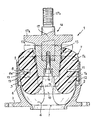
- variable strength spring according to the present invention, described therein, with reference to the enclosed drawing, given only for indicative and not limitative aim, in which the unique figure represents the spring in reference sectioned according to a longitudinal median plane.
- variable strength spring according to the present invention.
- the spring 1 includes a tubolar body 2 of circular shape, provided with a connection flange 3 by which same tubolar body 2 can be fixed to the non-suspended mass of a railway waggon.
- a contrast seat 4 Inside the tubular body is coaxially housed, in correspondence of its own end, a contrast seat 4 and an inner cylindric surface 5.
- a stopping seat 6 is foreseen, which is radially extending inside tubular body 2, whose aims will be better shown further on.
- an elastic ring 7 made of elastomeric material of suitable rigidity, which is provided with a groove 8 radially extended from outside towards inside.
- the groove 8 divides the longitudinal length of elastic ring 7 in a first portion 7a and in a second portion 7b.
- the groove 8 is located on the longitudinal length of ring 7 at a position such that the area of the ring section 7 is equally divided between the first portion 7a and the second portion 7b.
- the ratio value between the radial deepness of the groove 8 and the original radial thickness of the elastic ring 7 at that longitudinal position is comprised between 0.4 and 0.6, i.e. the radial deepness is comprised between 40% and 60% of the original radial thickness in correspondence of the groove.
- the width of the groove 8 is not of considerable importance to the aims of a suitable functioning of spring 1. It is however foreseen that groove 8 finishes, inside ring 7, by a suitably joined- end 8a, to avoid points of major vulnerability in which ruptures of elastic ring 7 may occur.
- the first portion 7a appears fast to the tubular body 2 and it is disposed on the opposite side in respect to the contrast seat 4. Precisely, the first portion 7a is fixed by a rubber-metal connection to a flange 9, which is, on its turn, fast to the tubolar body 2.
- the second portion 7b presents a check surface 10 suitable shaped and turned towards the contrast seat 4 which is, outwardly, provided with the annular rigid element 11, which is fast to the same contrast seat by a rubber-metal connection.
- the annular element 11 is slidely engaged along the inner cylindric surface 5 and presents an advantageous rabbet edge 12 contrapposed to the stopping seat 6 and spaced from said stopping seat according to a pre-determined measure.
- the spring 1 comprises a connection tang 14 which connects spring 1 to the suspended mass of a waggon; this connection tang is fixed inside the elastic ring 7.
- connection tang 14 is preferably constituted by a tronco-conic element 15 rigidly engaged inside the elastic ring 7 by a rubber-metal connection. Furthermore, the connection area between elastic ring 7 and the tronco-conic element 15 is substantially identic to the fastening area of first portion 7a to the flange 9 fixed to the tubolar body 2.
- connection portion 17 To the tronco-conic element 15 is removably associated, by a bolt 16, a connection portion 17.
- the latter presents an annular shoulder 17a radially extending over the elastic ring 7 and a threaded portion 17b disposed on the opposite side in respect to the tronco-conic element 15.
- connection tang 14 and the tubolar body 2 are mutually approaching, contrasted by the action noteded by the elastic ring 7.
- connection tang 14 and tubolar body 2 are only contrasted by the elastic reaction of first portion 7a, which is substantially deformed due to the shearing stresses.
- the second portion 7b does not contrast at all the action of load, as it is freely slidable along the inner cylindric surface 5.
- the strength value of spring 1 is therefore subject to be ulteriourly increased when, by further increase of load acting on same spring, the checking surface 10 is put in contact with the contrast seat 4, as clearly oulined with a sketched line as per enclosed drawing.
- the mutual approaching between connection tang 14 and tubolar body 2 is also contrasted by compression stresses induced by elastic ring 7 by the action determined between contrast seat 4 and same elastic ring 7.
- the checking surface 10 and the contrast seat 4 are shaped in order to enter in contact according to area progressively growing by the load increase. As a consequence of the above, said compression stresses, and consequently the rigidity of spring 1, are subject to grow progressively by the load increase acting on spring 1.
- the invention aims are achieved.
- the spring in reference presents a first value of constant rigidity, during starting phase of shearing stress, a second value of constant rigidity, major than first value, during the second phase of shearing stress, and a further rigidity increase during the phase of shearing stress and compression.
- the rigidity values of the spring according to the invention are substantially maintained under the correspondent rigidity values of the known springs during the phases of shearing stress, in order to reach the same values of the traditional springs during shearing stress and compression working phases.
Landscapes
- Engineering & Computer Science (AREA)
- General Engineering & Computer Science (AREA)
- Mechanical Engineering (AREA)
- Springs (AREA)
- Vibration Prevention Devices (AREA)
Description
- The present invention relates to a variable strength spring, comprising a tubular body to which inner is situated a contrast seat, concave and coaxial in respect to the tubolar body, a ring made of elastomeric material coaxially engaged into the tubolar body and having a checking surface turned towards said contrast seat and a connection tang rigidly engaged in the elastic ring on the opposite side in respect to the checking surface. Such a variable strength spring is known from the GB-A-872 230.
- It is known that springs of said type are particularly suitable to be used in realizing suspensions for transport vehicles, for example railway waggons, which are subject to support considerable variations of static load.
- It is observed that springs destined to said uses must present, as essential characteristic, a growing rigidity by the increase of static load to which they are asked to support.
- Considering the behaviour of suspensions in railway waggons, springs must present a relatively reduced rigidity when the waggon is unloaded (load acting on each spring equal to 800 - 900 kgf, approximately) or when the transported load is of weight relatively low. This is a necessary condition to avoid that, during running, undesirable disengagements between wheel and rail might occur due to unavoidable unevenness, particularly in connection with frogs between railways. In conditions of a limited static load, a low strength of spring is essential, also to avoid that various impacts supported by wheels during running are entirely sent to the suspended mass.
- Vice versa, when the static load is of a considerable entity (4200-4800 Kgf.), springs must have a high strength, so that in situation of static load variations, do not correspond excessive variations of springs arrow and, hence, excessive vertical movements of the vehicle centre gravity.
- To satisfy these needs, springs which comprise essentially a shaped elastic ring are utilized; this shaped elastic ring is realized in elastomeric material of suitable rigidity, which is rigidly and coaxially engaged inside the tubolar body.
- The tubolar body is shaped in order to present coaxially, at its inner, a concave contrast seat connecting with a cylindric wall inside the tubular body. Such contrast seat appears turned towards the elastic ring and suitably spaced by the same.
- In the elastic ring is also rigidly engaged a connection tang, whose a fastening portion protrudes from the same ring on the opposite side in respect of the above mentioned contrast seat.
- The assembling of spring foresees, substantially, that either the tubolar body or the connection tang are respectively fixed to the parts under relative movement, i.e. to the suspended mass and to the non-suspended mass of the vehicle and vice versa. In such a situation the loads sent to the spring are hindered by the consequent elastic deformations of the ring.
- Choosing suitable ways for the various spring components, it is possible to confer to said spring, a rigidity that, within certain limits, grows by the static load increase.
- In the present solutions, it is foreseen that, when spring must support loads relatively reduced, the entire section of the deformable ring appears substantially stressed to shearing stress. In such a situation the elastic ring is susceptible of deformations relatively high under the action of load variations and the spring shows a rigidity relatively reduced whose value remains substantially constant within certain limits of load. In these limits the elastic ring is deforming moving in the tubular body without interferring with the contrast seat foreseen in said tubolar body. When the load increases beyond the above mentioned limits, the elastic ring, deforming itself, goes progressively in contact, by its checking surface duly shaped, with the above mentioned contrast seat.
- In such a situation, the elastic ring is also stressed to compression, with stresses little by little growing up, while the contrast surface inhibits further deformations. By this, it is determined a considerable raise of spring rigidity by the load increase.
- It is noted that known spring, although they allow to get rigidity variations, by the increase of static load, they don't have shown, up to now, a full satisfactory behaviour.
- As a matter of fact, as appears from what hereabove described, the rigidity of said springs is substantially subjected to raise by the increase of load, only after that the same load has exceeded a pre-determined value.
- The main purpose of the present invention is of eliminating such drawback, realizing a variable strength spring also when it must support loads relatively reduced.
- This aim and others, which will now be better understood from the following detailed description, are substantially achieved by a variable strength spring, including:
- a tubular body to which inner there is a contrast seat, concave and coaxial in respect to the same tubular body;
- an elastic ring coaxially engaged in the tubolar body and having a checking surface turned towards said contrast seat;
- a connection tang rigidly engaged in the elastic ring in the opposite side in respect to the supporting surface, characterized by the fact of comprising:
- a perimetral groove extending towards the inner of the elastic ring which defines, substantially, on the longitudinal length of said elastic ring, a first portion fast to the tubolar body and disposed on the opposite side in respect to the contrast seat and a second portion slidely engaged in the tubular body;
- a rabbet edge disposed on the outer perimetral length of said second portion;
- a stopping area housed inside the tubolar body, said stopping area being destined to interferes with said rabbet edge in order to stop the run of the second portion when the connecting tang appears displaced towards the tubolar body beyond a pre-determined limit.
- Further characteristics and advantages will be better shown from the following detailed description of a preferred but not exclusive execution of a variable strength spring, according to the present invention, described therein, with reference to the enclosed drawing, given only for indicative and not limitative aim, in which the unique figure represents the spring in reference sectioned according to a longitudinal median plane.
- With reference to that figure, by 1 has been globally indicated a variable strength spring, according to the present invention.
- The spring 1 includes a
tubolar body 2 of circular shape, provided with aconnection flange 3 by whichsame tubolar body 2 can be fixed to the non-suspended mass of a railway waggon. Inside the tubular body is coaxially housed, in correspondence of its own end, acontrast seat 4 and an innercylindric surface 5. Originally, between contrast seat and the innercylindric surface 5, a stoppingseat 6 is foreseen, which is radially extending insidetubular body 2, whose aims will be better shown further on. - Inside
tubular body 2 is coaxially engaged anelastic ring 7, made of elastomeric material of suitable rigidity, which is provided with agroove 8 radially extended from outside towards inside. - Substantially, the
groove 8 divides the longitudinal length ofelastic ring 7 in afirst portion 7a and in a second portion 7b. - Considering a preferred embodiment, it is foreseen that the
groove 8 is located on the longitudinal length ofring 7 at a position such that the area of thering section 7 is equally divided between thefirst portion 7a and the second portion 7b. - Preferably, the ratio value between the radial deepness of the
groove 8 and the original radial thickness of theelastic ring 7 at that longitudinal position, is comprised between 0.4 and 0.6, i.e. the radial deepness is comprised between 40% and 60% of the original radial thickness in correspondence of the groove. The width of thegroove 8 is not of considerable importance to the aims of a suitable functioning of spring 1. It is however foreseen thatgroove 8 finishes, insidering 7, by a suitably joined-
end 8a, to avoid points of major vulnerability in which ruptures ofelastic ring 7 may occur. - The
first portion 7a appears fast to thetubular body 2 and it is disposed on the opposite side in respect to thecontrast seat 4. Precisely, thefirst portion 7a is fixed by a rubber-metal connection to aflange 9, which is, on its turn, fast to thetubolar body 2. - The second portion 7b presents a
check surface 10 suitable shaped and turned towards thecontrast seat 4 which is, outwardly, provided with the annularrigid element 11, which is fast to the same contrast seat by a rubber-metal connection. - The
annular element 11 is slidely engaged along the innercylindric surface 5 and presents anadvantageous rabbet edge 12 contrapposed to the stoppingseat 6 and spaced from said stopping seat according to a pre-determined measure. - It is also foreseen that between the
annular element 11 and the innercylindric surface 5 of thetubolar body 2, are interposed two or more slidingrings 13 made of low friction coefficient material. - Moreover, the spring 1 comprises a
connection tang 14 which connects spring 1 to the suspended mass of a waggon; this connection tang is fixed inside theelastic ring 7. - The
connection tang 14 is preferably constituted by a tronco-conic element 15 rigidly engaged inside theelastic ring 7 by a rubber-metal connection. Furthermore, the connection area betweenelastic ring 7 and the tronco-conic element 15 is substantially identic to the fastening area offirst portion 7a to theflange 9 fixed to thetubolar body 2. - To the tronco-
conic element 15 is removably associated, by abolt 16, aconnection portion 17. The latter presents anannular shoulder 17a radially extending over theelastic ring 7 and a threaded portion 17b disposed on the opposite side in respect to the tronco-conic element 15. - After having described all the above in a structural way, this is now the functioning of the spring in reference.
- When spring is asked to support load, the connection tang 14 and the
tubolar body 2, are mutually approaching, contrasted by the action exercited by theelastic ring 7. - Originally, when spring 1 must bear loads of entity relatively reduced, the trend of a mutual approaching between
connection tang 14 andtubolar body 2 is only contrasted by the elastic reaction offirst portion 7a, which is substantially deformed due to the shearing stresses. The second portion 7b does not contrast at all the action of load, as it is freely slidable along the innercylindric surface 5. - In such a situation, the static load variations sent to spring 1 will cause relative displacements between the
connection tang 14 and thetubolar body 2 of relatively high entity. In other words, spring 1 will present a rigidity relatively low. - By the growing of load, a progressive approaching of
rabbet edge 12 towards stoppingseat 6, foreseen insidetubolar body 2, will occur. In this brief phase the spring rigidity 1 remains almost constant, until when, a pre-determined load value is achieved, a mutual contact betweenrabbet edge 12 and stoppingseat 6 will occur. - When reached and exceeded said value, the load acting on spring 1 is also contrasted by the action determined by the consequent deformation of second portion 7b which is under shearing stress. The spring 1 rigidity appears therefore increased, as the loads that act on same spring are contrasted by the elastic reactions exercised by the whole section of
elastic ring 7. - The strength value of spring 1 is therefore subject to be ulteriourly increased when, by further increase of load acting on same spring, the checking
surface 10 is put in contact with thecontrast seat 4, as clearly oulined with a sketched line as per enclosed drawing. In such a situation, in fact, the mutual approaching betweenconnection tang 14 andtubolar body 2 is also contrasted by compression stresses induced byelastic ring 7 by the action determined betweencontrast seat 4 and sameelastic ring 7. - The checking
surface 10 and thecontrast seat 4 are shaped in order to enter in contact according to area progressively growing by the load increase. As a consequence of the above, said compression stresses, and consequently the rigidity of spring 1, are subject to grow progressively by the load increase acting on spring 1. - The invention aims are achieved.
- As a matter of fact, whereas known springs have a constant rigidity during phase of shearing stress and a rigidity increase during phase of shearing stress and compression, the spring in reference presents a first value of constant rigidity, during starting phase of shearing stress, a second value of constant rigidity, major than first value, during the second phase of shearing stress, and a further rigidity increase during the phase of shearing stress and compression.
- It is also underlined that, advantageously, the rigidity values of the spring according to the invention, are substantially maintained under the correspondent rigidity values of the known springs during the phases of shearing stress, in order to reach the same values of the traditional springs during shearing stress and compression working phases.
- It is also understood that the above means a better behaviour of the spring, particularly in functioning conditions comprising low and medium load.
- More specifically, to satisfy particular requirements, it is also possible to foresee more movable portions 7b separated by
grooves 8 and destined to interfer in succession with asmany stoppings areas 6.
Claims (7)
- A variable strength spring (1), comprising:- a tubular body (2) to which inside is defined a concave, coaxial contrast seat (4) in respect to same tubular body;- an elastic ring (7) coaxially engaged inside the tubular body (2) and showing a checking surface (10) turned towards said contrast seat (4);- a connection tang (14) rigidly engaged in the elastic ring (7) on the opposite side in respect to the checking surface (10),
characterized by the fact of comprising:- a perimetral groove (8) extending itself towards the inside of said elastic ring (7) which substantially defines on the longitudinal length of the latter a first portion (7a) fast in respect to said tubular body (2) and disposed on the opposite side of the contrast seat, and a second portion (7b) slidely engaged inside the tubular body;- a rabbet edge (12) disposed on the outer perimetral length of said second portion (7b);- a stopping seat (6) obtained inside of the tubular body, said stopping seat being destined to interfere with said rabbet edge (12) to stop the run of said second portion (7a) when the connection tang (14) appears moved towards the tubular body beyond a pre-determined measure. - A spring as claimed in claim 1, characterized by the fact that said groove (8) is located at a longitudinal position such that the area of the elastic ring section is equally divided between said first (7a) and second (7b) portion.
- A spring as claimed in claim 1, characterized by the fact that said groove (8) is substantially radially extending with a radial deepness comprised between 40% and 60% of the original radial thickness of the elastic ring (7) at said longitudinal position.
- A spring as claimed in claim 1, characterized by the fact that said rabbet edge (12) is disposed on an annular element rigidly engaged to said second portion (7b).
- A spring as claimed in claim 1, characterized by the fact that between said second portion (7b) and the tubular body (2) is interposed a couple of sliding rings (13) made of a material of a low friction coefficient.
- A spring as claimed in claim 1, characterized by the fact that said first portion (7a) appears linked to the tubular body (2) according to a fastening area which is equal to the fastening area between the connection tang (14) and the elastic ring (2).
- A spring as claimed in claim 1, characterized by the fact that between said rigid annular element (11) and said tubular body (2) is disposed a couple of sliding rings (13) made of a material of a low friction coefficient
Applications Claiming Priority (2)
| Application Number | Priority Date | Filing Date | Title |
|---|---|---|---|
| IT19540/87A IT1202605B (en) | 1987-03-02 | 1987-03-02 | SPRING WITH VARIABLE RIGIDITY |
| IT1954087 | 1987-03-02 |
Publications (3)
| Publication Number | Publication Date |
|---|---|
| EP0280937A2 EP0280937A2 (en) | 1988-09-07 |
| EP0280937A3 EP0280937A3 (en) | 1989-09-27 |
| EP0280937B1 true EP0280937B1 (en) | 1991-09-25 |
Family
ID=11158890
Family Applications (1)
| Application Number | Title | Priority Date | Filing Date |
|---|---|---|---|
| EP88101933A Expired EP0280937B1 (en) | 1987-03-02 | 1988-02-10 | Variable strength spring |
Country Status (6)
| Country | Link |
|---|---|
| US (1) | US4936558A (en) |
| EP (1) | EP0280937B1 (en) |
| JP (1) | JPH01229135A (en) |
| DE (1) | DE3865039D1 (en) |
| ES (1) | ES2025712T3 (en) |
| IT (1) | IT1202605B (en) |
Families Citing this family (6)
| Publication number | Priority date | Publication date | Assignee | Title |
|---|---|---|---|---|
| US5881981A (en) * | 1997-06-30 | 1999-03-16 | Pearl Musical Instrument Co. | Elastomeric spring |
| US6601818B1 (en) * | 2000-10-12 | 2003-08-05 | Lord Corporation | Tilting mount with integral flange |
| DE102005028565A1 (en) * | 2005-06-21 | 2007-01-04 | Contitech Luftfedersysteme Gmbh | Highly elastic layered spring |
| SE528883C2 (en) * | 2005-06-30 | 2007-03-06 | Volvo Lastvagnar Ab | Rubber spring for a wheel axle suspension of a vehicle |
| DE102008052756A1 (en) * | 2008-10-22 | 2010-04-29 | Magna Steyr Fahrzeugtechnik Ag & Co. Kg | Wheel suspension for use in motor vehicle, has elastic component transmitting forces between medium and spring and/or between body and spring, where forces are transmitted to transmission section of elastic component by contact |
| JP5256162B2 (en) * | 2009-10-03 | 2013-08-07 | 東海ゴム工業株式会社 | Axle spring rubber for axle box support device for railway vehicle and method for manufacturing the same |
Family Cites Families (15)
| Publication number | Priority date | Publication date | Assignee | Title |
|---|---|---|---|---|
| US2069270A (en) * | 1935-05-23 | 1937-02-02 | Transit Res Corp | Elastic spring and method of making same |
| US2117264A (en) * | 1935-08-06 | 1938-05-10 | Firestone Tire & Rubber Co | Resilient support |
| BE432309A (en) * | 1938-11-05 | |||
| US2245296A (en) * | 1939-12-13 | 1941-06-10 | Transit Res Corp | Spring |
| US2242212A (en) * | 1940-07-26 | 1941-05-20 | Pennsylvania Railroad Co | Springing for railway trucks |
| FR55068E (en) * | 1946-05-28 | 1951-06-06 | Suspension for light vehicle wheels | |
| US2553188A (en) * | 1946-11-05 | 1951-05-15 | Overniter Mfg Corp | Rubber spring and axle assembly |
| NL109403C (en) * | 1958-05-27 | |||
| FR1237211A (en) * | 1959-06-10 | 1960-07-29 | Luxembourg Brev Participations | Improvements to rubber compression springs |
| GB890032A (en) * | 1959-10-13 | 1962-02-21 | Metalastik Ltd | Resilient mountings or springs |
| DE1163165B (en) * | 1961-06-06 | 1964-02-13 | Hansens Gummi & Packungswerke | Elastic spring for vehicles with a rubber spring body mounted in an external guide |
| GB1024554A (en) * | 1962-02-05 | 1966-03-30 | Angus George Co Ltd | Improvements in and relating to compression spring elements of elastomeric material |
| FR1434610A (en) * | 1965-05-03 | 1966-04-08 | Gomma Antivibranti Applic | Elastic suspension group, in particular for motor vehicles, with progressive characteristics |
| GB1090566A (en) * | 1965-05-03 | 1967-11-08 | Aeon Products London Ltd | Improvements in and relating to springs |
| AU523318B2 (en) * | 1980-06-23 | 1982-07-22 | Bridgestone Tire Co. Ltd. | Rubber vibration isolators |
-
1987
- 1987-03-02 IT IT19540/87A patent/IT1202605B/en active
-
1988
- 1988-02-10 DE DE8888101933T patent/DE3865039D1/en not_active Expired - Fee Related
- 1988-02-10 ES ES198888101933T patent/ES2025712T3/en not_active Expired - Lifetime
- 1988-02-10 EP EP88101933A patent/EP0280937B1/en not_active Expired
- 1988-03-02 JP JP63049459A patent/JPH01229135A/en active Pending
-
1989
- 1989-06-09 US US07/364,497 patent/US4936558A/en not_active Expired - Lifetime
Also Published As
| Publication number | Publication date |
|---|---|
| IT8719540A0 (en) | 1987-03-02 |
| JPH01229135A (en) | 1989-09-12 |
| US4936558A (en) | 1990-06-26 |
| ES2025712T3 (en) | 1992-04-01 |
| EP0280937A2 (en) | 1988-09-07 |
| DE3865039D1 (en) | 1991-10-31 |
| IT1202605B (en) | 1989-02-09 |
| EP0280937A3 (en) | 1989-09-27 |
Similar Documents
| Publication | Publication Date | Title |
|---|---|---|
| US3434708A (en) | Two-stage rubber vehicle suspension | |
| CA1183724A (en) | Primary suspension system for a railway car | |
| US4362109A (en) | Railway vehicle trucks | |
| US2514034A (en) | Means for supporting railway cars on their trucks | |
| US4475722A (en) | Suspension strut | |
| AU650942B2 (en) | Dual-stage tapered leaf spring for a trailer | |
| EP0280937B1 (en) | Variable strength spring | |
| CA1042957A (en) | Articulated railway service wheel and unitary railway hub and axle | |
| US5018566A (en) | Multi-part bolted steel rim | |
| US4662615A (en) | Suspension strut | |
| US4733855A (en) | Tapered rubber spring units | |
| US4473216A (en) | Suspension strut | |
| US2832587A (en) | Spring booster assemblies | |
| US2923570A (en) | Elastic wheel | |
| US4573554A (en) | Disc brake with caliper stabilizing tie-bar | |
| US4004525A (en) | Fluid truck snubber | |
| US2702701A (en) | Vehicle suspension | |
| CA1202988A (en) | Wheel suspension with eccentric shear disc | |
| KR100191878B1 (en) | A rail vehicle wheel | |
| JP2811569B2 (en) | Leaf spring and leaf spring assembly | |
| US5386895A (en) | Current collector | |
| US3010411A (en) | Suspension systems of tire-mounted bogie trucks with lateral guide means | |
| US3005629A (en) | Self-adjusting stabilizer for spring suspension | |
| EP0284783B1 (en) | Element for supporting the suspensionsprings of railway wagons and suchlike | |
| US4314725A (en) | Ring damped composite transit wheel |
Legal Events
| Date | Code | Title | Description |
|---|---|---|---|
| PUAI | Public reference made under article 153(3) epc to a published international application that has entered the european phase |
Free format text: ORIGINAL CODE: 0009012 |
|
| AK | Designated contracting states |
Kind code of ref document: A2 Designated state(s): CH DE ES FR GB LI SE |
|
| PUAL | Search report despatched |
Free format text: ORIGINAL CODE: 0009013 |
|
| AK | Designated contracting states |
Kind code of ref document: A3 Designated state(s): CH DE ES FR GB LI SE |
|
| 17P | Request for examination filed |
Effective date: 19891128 |
|
| 17Q | First examination report despatched |
Effective date: 19900711 |
|
| GRAA | (expected) grant |
Free format text: ORIGINAL CODE: 0009210 |
|
| AK | Designated contracting states |
Kind code of ref document: B1 Designated state(s): CH DE ES FR GB LI SE |
|
| REF | Corresponds to: |
Ref document number: 3865039 Country of ref document: DE Date of ref document: 19911031 |
|
| ET | Fr: translation filed | ||
| REG | Reference to a national code |
Ref country code: ES Ref legal event code: FG2A Ref document number: 2025712 Country of ref document: ES Kind code of ref document: T3 |
|
| PLBE | No opposition filed within time limit |
Free format text: ORIGINAL CODE: 0009261 |
|
| STAA | Information on the status of an ep patent application or granted ep patent |
Free format text: STATUS: NO OPPOSITION FILED WITHIN TIME LIMIT |
|
| 26N | No opposition filed | ||
| EAL | Se: european patent in force in sweden |
Ref document number: 88101933.5 |
|
| PGFP | Annual fee paid to national office [announced via postgrant information from national office to epo] |
Ref country code: SE Payment date: 19990225 Year of fee payment: 12 |
|
| PGFP | Annual fee paid to national office [announced via postgrant information from national office to epo] |
Ref country code: FR Payment date: 19990226 Year of fee payment: 12 Ref country code: ES Payment date: 19990226 Year of fee payment: 12 |
|
| PGFP | Annual fee paid to national office [announced via postgrant information from national office to epo] |
Ref country code: GB Payment date: 19990304 Year of fee payment: 12 |
|
| PGFP | Annual fee paid to national office [announced via postgrant information from national office to epo] |
Ref country code: DE Payment date: 19990305 Year of fee payment: 12 |
|
| PGFP | Annual fee paid to national office [announced via postgrant information from national office to epo] |
Ref country code: CH Payment date: 19990324 Year of fee payment: 12 |
|
| PG25 | Lapsed in a contracting state [announced via postgrant information from national office to epo] |
Ref country code: GB Free format text: LAPSE BECAUSE OF NON-PAYMENT OF DUE FEES Effective date: 20000210 |
|
| PG25 | Lapsed in a contracting state [announced via postgrant information from national office to epo] |
Ref country code: SE Free format text: LAPSE BECAUSE OF NON-PAYMENT OF DUE FEES Effective date: 20000211 Ref country code: ES Free format text: LAPSE BECAUSE OF NON-PAYMENT OF DUE FEES Effective date: 20000211 |
|
| PG25 | Lapsed in a contracting state [announced via postgrant information from national office to epo] |
Ref country code: LI Free format text: LAPSE BECAUSE OF NON-PAYMENT OF DUE FEES Effective date: 20000229 Ref country code: CH Free format text: LAPSE BECAUSE OF NON-PAYMENT OF DUE FEES Effective date: 20000229 |
|
| GBPC | Gb: european patent ceased through non-payment of renewal fee |
Effective date: 20000210 |
|
| EUG | Se: european patent has lapsed |
Ref document number: 88101933.5 |
|
| REG | Reference to a national code |
Ref country code: CH Ref legal event code: PL |
|
| PG25 | Lapsed in a contracting state [announced via postgrant information from national office to epo] |
Ref country code: FR Free format text: LAPSE BECAUSE OF NON-PAYMENT OF DUE FEES Effective date: 20001031 |
|
| PG25 | Lapsed in a contracting state [announced via postgrant information from national office to epo] |
Ref country code: DE Free format text: LAPSE BECAUSE OF NON-PAYMENT OF DUE FEES Effective date: 20001201 |
|
| REG | Reference to a national code |
Ref country code: FR Ref legal event code: ST |
|
| REG | Reference to a national code |
Ref country code: ES Ref legal event code: FD2A Effective date: 20010910 |