EP0280397A2 - Endoscope - Google Patents
Endoscope Download PDFInfo
- Publication number
- EP0280397A2 EP0280397A2 EP88300562A EP88300562A EP0280397A2 EP 0280397 A2 EP0280397 A2 EP 0280397A2 EP 88300562 A EP88300562 A EP 88300562A EP 88300562 A EP88300562 A EP 88300562A EP 0280397 A2 EP0280397 A2 EP 0280397A2
- Authority
- EP
- European Patent Office
- Prior art keywords
- endoscope
- light
- viewing
- optical
- coupling means
- Prior art date
- Legal status (The legal status is an assumption and is not a legal conclusion. Google has not performed a legal analysis and makes no representation as to the accuracy of the status listed.)
- Granted
Links
Images


Classifications
-
- A—HUMAN NECESSITIES
- A61—MEDICAL OR VETERINARY SCIENCE; HYGIENE
- A61B—DIAGNOSIS; SURGERY; IDENTIFICATION
- A61B1/00—Instruments for performing medical examinations of the interior of cavities or tubes of the body by visual or photographical inspection, e.g. endoscopes; Illuminating arrangements therefor
- A61B1/313—Instruments for performing medical examinations of the interior of cavities or tubes of the body by visual or photographical inspection, e.g. endoscopes; Illuminating arrangements therefor for introducing through surgical openings, e.g. laparoscopes
- A61B1/317—Instruments for performing medical examinations of the interior of cavities or tubes of the body by visual or photographical inspection, e.g. endoscopes; Illuminating arrangements therefor for introducing through surgical openings, e.g. laparoscopes for bones or joints, e.g. osteoscopes, arthroscopes
-
- A—HUMAN NECESSITIES
- A61—MEDICAL OR VETERINARY SCIENCE; HYGIENE
- A61B—DIAGNOSIS; SURGERY; IDENTIFICATION
- A61B1/00—Instruments for performing medical examinations of the interior of cavities or tubes of the body by visual or photographical inspection, e.g. endoscopes; Illuminating arrangements therefor
- A61B1/00112—Connection or coupling means
- A61B1/00121—Connectors, fasteners and adapters, e.g. on the endoscope handle
- A61B1/00126—Connectors, fasteners and adapters, e.g. on the endoscope handle optical, e.g. for light supply cables
-
- A—HUMAN NECESSITIES
- A61—MEDICAL OR VETERINARY SCIENCE; HYGIENE
- A61B—DIAGNOSIS; SURGERY; IDENTIFICATION
- A61B1/00—Instruments for performing medical examinations of the interior of cavities or tubes of the body by visual or photographical inspection, e.g. endoscopes; Illuminating arrangements therefor
- A61B1/00112—Connection or coupling means
- A61B1/00121—Connectors, fasteners and adapters, e.g. on the endoscope handle
- A61B1/00128—Connectors, fasteners and adapters, e.g. on the endoscope handle mechanical, e.g. for tubes or pipes
-
- A—HUMAN NECESSITIES
- A61—MEDICAL OR VETERINARY SCIENCE; HYGIENE
- A61B—DIAGNOSIS; SURGERY; IDENTIFICATION
- A61B1/00—Instruments for performing medical examinations of the interior of cavities or tubes of the body by visual or photographical inspection, e.g. endoscopes; Illuminating arrangements therefor
- A61B1/04—Instruments for performing medical examinations of the interior of cavities or tubes of the body by visual or photographical inspection, e.g. endoscopes; Illuminating arrangements therefor combined with photographic or television appliances
- A61B1/042—Instruments for performing medical examinations of the interior of cavities or tubes of the body by visual or photographical inspection, e.g. endoscopes; Illuminating arrangements therefor combined with photographic or television appliances characterised by a proximal camera, e.g. a CCD camera
Definitions
- This invention relates to small diameter endoscopes and more particularly to such an endoscope having a coupling means on the proximate end for releasable attachment to viewing means for viewing by the surgeon such as on a video screen or monitor for example.
- the endoscope may be attached to an eyepiece.
- U.S.-A-3 858 577 to Bass, et al. discloses an endoscope of substantial size for performing laser surgery.
- conventional light is used through fibre optics to illuminate the operating site and laser light is used to perform a surgical procedure.
- U.A.-A-4 011 403 to Epstein, et al. discloses a fibre-optic laser endoscope.
- the device utilizes a laser beam as a light source and an optical fibre as a light transmitter.
- the sensing means includes a TV camera located at the investigated site.
- the laser beam produces radiation at three different wavelengths which produce white light. Ultraviolet or infrared light can also be used.
- the camera is separate from the fibre-optics and the laser.
- U.S.-A-14 313 431 to Frank discloses an endoscope using a laser light source with a light-conducting fibre. This device is used for irradiating bladder tumours utilizing the laser light beam.
- an endoscope having a micro-thin diameter, is provided having an interface connector at the proximate end thereof for removably plugging into a receptacle in a video monitor.
- the endoscopes can be separately sterilized and can be easily replaced should it become damaged.
- the endoscope disclosed in that patent can no longer be used to complete the operation. This necessitates removal and replacement of the endoscope with another one having an integral eyepiece for viewing the body cavity. This requires extra time and inconvenience and is not desirable from the standpoint of the surgeon or the patient. It also produces only a black and white image.
- Another device which is currently available is an imaging lavage endoscope sold under the trademark VISICATH by Microvasive of Milford, Massachusetts, U.S.A.
- VISICATH by Microvasive of Milford, Massachusetts, U.S.A.
- This device has an eyepiece with a separable endoscope so that the endoscope can be replaced, should it become damaged. This results in a cost saving since the eyepiece does not have to be replaced.
- Both the eyepiece and the endoscope are sterilizable.
- the eyepiece is not usable with a console. Thus, in the use of this device the sterility is destroyed as soon as the physician puts the eyepiece against his face.
- An eyepiece requires an optical light cable to transmit light from a light source to the endoscope.
- Each manufacturer of optical light cables supplies them with different sized fittings at each end. This results in confusuib and frustration in the operation room in trying to find an optical light cable whose fittings match with those of the light source and the eyepiece.
- a sterilizable small diameter endoscope for viewing and/or treatment within body cavities by nonsurgical or micro-surgical procedures and having a distal end for insertion into a body cavity and a proximate end, said endoscope being characterised by a coherent fibre optical bundle having a micro-thin diameter and extending from said distal end to a point adjacent said proximate end and having a planar surface at its proximate end, a plurality of light transmitting fibres spaced around said optical bundle, a tubular outer cover extending over said fibres to hold them in place, said outer cover extending from said distal end to a point spaced from said proximate end, optical lens means at said distal end of said optical bundle to focus an image of a portion of the cavity on said distal end of said optical bundle for transmission through said optical bundle, and a coupling means for removably connecting the endoscope to a viewing means in fixed angular relationship, the coupling means being fixedly attached to said proximate end
- a method of using a sterilizable endoscope for viewing and/or treatment within body cavities by nonsurgical or micro-surgical procedures which has a distal end for insertion into the body cavity and a proximate end with coupling means of no greater diameter than the body of the endoscope, said method being characterised by the steps of inserting the distal end into the body cavity, attaching a first removable optical viewing means to the coupling means to view the body cavity, disconnecting the first removable optical viewing means from the coupling means, and attaching a second removable optical viewing means to the coupling means to view the body cavity.
- a method of detecting abnormal cells in a patient characterised by the steps of giving the patient a fluorescent drug which localizes in the abnormal cells, irradiating the body area containing the abnormal cells with a light of a first frequency which will cause the abnormal cells to fluoresce, and treating the abnormal cells by irradiating them with laser light of a second frequency to destroy the abnormal cells.
- a sterilizable small diameter endoscope C includes a cable assembly 10 which is provided at its distal end with a lens 12 and at its proximate end with a coupling means 14.
- a coherent fibre-optical bundle 16 At the centre of the cable is a coherent fibre-optical bundle 16.
- a tubular inner cover 18 extends around coherent optical bundle 16 at each end and may be formed of a heat shrinkable Teflon (trade mark) of PVC material which extends along the coherent optical bundle from the distal end to the proximate end.
- Placed around inner covering 18 is a plurality of light carrying bundles 20 which are made up of individual fibres which do not have to be coherent.
- bundles are for transmitting light from a suitable light source to the body cavity.
- bundle 20 may be replaced with a single flexible glass fibre.
- An outer cover 22 extends around the spaced light bundles 20, as shown and may also be constructed of a heat shrinkable Teflon (trade mark) material which extends from the distal end of cable assembly 10 to a position adjacent coupling means 14.
- the coupling means 14 is located at the proximate end of outer cover 22 and includes a longitudinal groove 24 for alignment with a mating rib in a viewing means or in a strain relieve unit for connection to a viewing means. It can be made of any suitable material, such as anodized aluminium or a machinable grade of plastics, such as Bakelite (trade mark).
- a strain relief unit 11 is also illustrated in Figure 1 which can be used to connect the endoscope either to a console or to an eyepiece, as will be more fully explained below.
- the strain relief unit 11 has a cylindrical body 26 having a fist tapered section 28 and a second smaller tapered section 30, as shown.
- the second tapered section 30 terminates at its distal end in a socket 32 having a longitudinal rib 34 alignable with groove 24 and held in place by locking nut 36.
- the other end of strain relief unit 11 has a male connector 38 which is receivable in a console or an emergency use eyepiece, as will be described more fully below.
- the endoscope can be connected to a eyepiece E as shown in Figure 2.
- the eyepiece E has a coupling means identical to that of strain relief unit 11 so that it can be coupled to endoscope C. It has a socket 32 ⁇ with a longitudinal rib 34 ⁇ which is alignable with the groove 24 of coupling means 14.
- the coupling means can be slid into the socket as best seen in Figure 2 and held in position by threaded locking nut 36.
- the proximate end of coupling means 14 and the fibres are flat and polished so as to come into contiguous face-to-face contact with a rod lens 40 for transmitting the light from the coherent fibre bundle to the user's eye which is held against the ocular face 42.
- groove 32 ⁇ with rib 34 ⁇ ensures that the image being transmitted by the coherent optical bundle 16 is in proper orientation with respect to lens 40 of eyepiece E.
- Light fibres 44 surround lens 40 and extend to a fixture 46 to which a suitable light source can be attached for illuminating the body cavity by transmitting light along fibres 44 and light bundles 20.
- FIG. 3 shows a trochar 50 which is illustrated as being inserted through the wall 52 of a body member and into a body cavity 54.
- the trochar has a first lumen 56 through which the endoscope C extends into the body cavity 54.
- a second lumen 58 is provided for any one of a number of purposes, such as for irrigation or treatment within the body cavity 54.
- trochars of this type may have more than two lumens, depending on their intended use.
- an eyepiece E such as one of the form shown in Figure 2, it can be removed by removing locking nut 36 and sliding the coupling means 14 of the endoscope out of socket 32 ⁇ . Since the coupling means 14 is no larger in diameter than outer cover 22, the trochar can be slid to the right, as viewed in Figure 3, while leaving endoscope C in place. After removal of trochar 50, the eyepiece E can be reconnected to the coupling means 14, as previously described. The surgeon can then resume his viewing of the body cavity, as required.
- the endoscope can also be used with a video console V, of the type shown in Figure 3.
- This console includes a video screen 60.
- the coupling means 14 of endoscope C is receivable in a socket 62 which is connected to a camera 64 by suitable optics 66 which includes a continuous focus zoom lens for transmitting the image to camera 64.
- a light source (not shown) is provided and is connected to optics 66 by light cable 70.
- socket 62 can be provided in a disc 72 which is mounted for rotation on the video console V about an axis 74 and is provided with a plurality of other sockets, such as sockets 76,78 and 80, as shown.
- the socket corresponding to the size of the endoscopes can be rotated to be in the position of socket 62, so as to be properly aligned with the optics 64.
- an important advantage is that when a cable assembly 10 of the endoscop becomes damaged and no longer usable, it can be replaced with another one without having to replace a corresponding eyepiece. Furthermore, the endoscope can be made to be moisture-impervious so that it can be easily sterilized for re-use. When used with a console, the sterility of the operating environment can be maintained since the surgeon does not need to put the eyepiece against his face.
- endoscope C extends through a maleable sheath 82 which extends through a body canal 84 and is conformed to the shape of the canal.
- the sheath 82 may include a laser fibre 86 for phototherapy or photocoagulation treatment within the body cavity into which the sheath and endoscope extend. Additionally, it may include a passageway 88 for irrigation or suction.
- a video console V ⁇ is shown in Figure 7 which is specifically constructed for use with the strain relief unit U which couples endoscope C to the console.
- a video monitor 90 is provided as a separate unit and is connected to the console by a signal transmitting cable 92.
- the console V ⁇ has a front panel 94 which contains the controls for the monitor camera, light source and filters, as well as a receptacle 96 for receiving strain relief unit U.
- the receptacle 96 is connected by means of a light cable 98 to a light source 100.
- the receptacle 96 is also connected to an optical assembly 102 which transmits the image from the cable to camera 104 for transmission by cable 92 to the monitor 90.
- the camera is connected to a camera power supply 106 and the lamp assembly is powered through light source power supply 108.
- a suitable power transformer 110 and fans 112 and 114 are provided.
- the male connector 38 carries an optical bundle 116 through the centre thereof which aligns with the optical bundle 16 in endoscope C at socket 32 and is polished at both ends so that light will be transmitted from one bundle to the next.
- a flat face 118 radiates outwardly from connector 38 to the peripheral surface of cylindrical body 26.
- the ends of light transmitting fibres 120 are spaced around this face and also have polished ends, the opposite ends thereof being aligned with the ends of light bundles 20 of endoscope C.
- Alignment pins 122 are provided on opposite side of connector 38 to align the light bundles and optical bundles with the corresponding light transmitting fibres within video console V ⁇ .
- connector 38 has a peripheral recess 126 for receiving a spring detent 128 in the receptacle 96 and thereby releasably holding the strain relief unit U in place in socket 129.
- An eyepiece E ⁇ as shown in Figures 10 and 11 can be connected to strain relief unit U as shown.
- the eyepiece includes a socket or receptacle 130 in which the male connector 38 extends.
- the light bundle thereof is aligned with lens 132 whereby the image is projected through glass window 134 onto the eye of the surgeon.
- the eyepiece E ⁇ is also provided with a light fixture 136 through which a bundle of light transmitting fibres 138 extends and terminates in peripherally spaced positions around the fact of the eyepiece for alignment with the light bundles 120 of strain relief unit U.
- a spring detent 140 extends into the peripheral groove 126 of male connector 38 and releasably holds the strain relief unit and eyepiece E ⁇ together.
- FIG. 12 Another form of the endoscope is shown at C ⁇ in Figures 12 to 16 and has an integral strain relief unit U ⁇ .
- the length of this device is approximately 190.5 centimetres (75 inches) to 203 centimetres (80 inches) in length and is very flexible.
- the tapered section is capable of accepting endoscopes of different diameters in the distal end.
- Each endoscope in Figures 12,14,15 and 16 has a different tip.
- a general purpose tip 142 is shown in Figure 12. This tip may be the same diameter as the endoscope or enlarged, as shown.
- the tip may include a stainless steel jacket 144, as best seen in Figure 13, or it may not have a metal covering at all and be very flexible.
- optical bundle 16 having a cover 18 and surrounded by spaced light bundles 20.
- a lens 146 is provided at the end of optical bundle 16 for focussing an image of the site being investigated on to the end of light bundle 16 for transmission to the viewing means.
- a long straight probe 148 which may be a stainless steel jacket made of #304 tempered stainless steel. Also, #316, #316L and INCONEL 600 (trade mark) steel may be used.
- This device may be used for insertion into various body passageways which are relatively straight.
- a maleable jacket 150 (shown in dotted lines) may be used which can be conformed to the passageway through which it is to extend.
- Such usage of this device might be as an arthroscope and the maleable material may be sterling silver. With this device the surgeon can bend it to fit his needs to see a particular part of the joint in which it is used. After the procedure is completed, it can be straightened for use in the next succeeding case.
- the device In small joints, such as a finger joint, the device might be approximately 1.0 mm in diameter. If it is intended for use in examining an ankle joint it might be 2.0 mm in diameter. For still larger joints like a knee joint, it might be 3.5 mm to 5.0 mm in diameter, or possibly larger.
- the metal sleeve can be approximately 15 centimetres (6 inches) to 20 centimetres (8 inches) in length.
- a maleable form of stainless steel might be used instead of sterling silver.
- a closely wound steel spring of appropriate length may be provided to slip over the maleable section to aid the surgeon to shape this section to desired configuration without crimping. This steel spring is them removed after shaping and set aside.
- the device is used as a hysteroscope it might be made less than 1.0 mm in diameter. This size is selected to allow passage of the device into the cervical canal without dilating the cervix. If made this small, the endoscope can be passed into the cervix along with other devices such as a special fibre-optic, possible of 200 to 400 microns diameter, for transmitting laser energy for photocoagulation as previously discussed with respect to Figure 5.
- a channel for either suction or irrigation can be provided. With the maleable sheath, the device can be preformed to the shape of the particular uterine cavity in which it is being used.
- an optical probe 152 is illustrated which has a rigid body portion 154 with a hand grip 156 and a curved rigid probe 158 which allows the physician directional stability so that he can point the device wherever he wants it to look around other body portions.
- FIG. 16 A still further embodiment is shown in Figure 16 wherein the endoscope C ⁇ extends into a protective stainless steel housing 160 which is attached to the side of a pair of forcepts 162, such as a laryngeal grasping device which might be used to extract a fish bone from the larynx.
- the metal tube is welded or otherwise attached to lower jaw 164 of the instrument.
- the upper jaw 166 can be moved relative to jaw 164 by squeezing handles 168 and 170 respectively.
- the endoscopes described and the console can be used as a fluorescence detector and provide a means for not only detecting abnormal cells but also for treating the cells by phototherapy and measuring the effectiveness of that treatment.
- the patient is given a drug which has a particular affinity to the abnormal cells and which will fluoresce when exposed to light of a prederermined first frequency.
- This light frequency can be transmitted through special light fibres of the endoscope onto the tissue being examined.
- Light of a second frequency which will kill the cells can be directed down the light fibres or through a separate and additional light fibre. If even a third light channel is provided, to permit the use of other light frequencies, various quantitative measurements can be done through the endoscope. In some situations, strobed light may be used.
- HPD hematoporphyrin derivative
- the oxygen content of the cell can be monitored by utilizing laser light to measure absorption spectra and by a spectrophotometer.
- a spectrophotometer e.g., a spectrophotometer
- the lamp and light source lamp assembly 100 can be changed, such as to a halogen light which provides a frequency in the visible range, or alternatively a band pass filter 172 can be inserted which allows transmission of only those light rays which fall within the desired frequency.
- the fluorescing cells will then transmit light through the optical assembly to camera 104.
- a second band pass filter 174 can be inserted between the optical assembly and the camera which allows transmission only of the reflective fluorescent light in the range of 630 nm.
- band pass filter 172 can be replaced by other filters, such as to permit transmission of light having a different frequency from the range 630 nm.
- the two frequencies of 410 nm and 630 nm can be strobed so that they are alternately sent along the light fibres for fluorescence and for killing the cells, respectively.
- the endoscope can be changed to provide fibres which are particularly effective for transmitting light in the 400 nm to 410 nm frequency range.
- Such fibres are available through Gallileo Electro-Optics Company of Sturbridge, Massachusetts, U.S.A. and other manufacturers.
- Another fluorescence detector compound which has been found effective is Rhodamine-123.
- an endoscope which has great versatility in that it may be used with either a substantially standard eyepiece or with a video camera and monitor.
- the endoscopes described can be provided in different sizes when used with a video monitor, which may contain a plurality of sockets for alignment with the optical means of the video camera for connection with a endoscope of the selected size.
- the endoscope can be used within the lumen of a trochar or operating channel of a larger endoscope and, since the eyepiece is removable, the trochar or larger endoscope can be removed without removing the basic endoscope and the eyepiece can then be replaced for further viewing.
- the endoscope can be easily replaced should it become damaged, without replacement of the expensive viewing means.
- the sterility of the endoscope can be maintained when used with the console, which permits its use with a lower risk of infection. Furthermore, no separate light cable is needed.
- the device can also be used for detection and treatment of cancer cells or other abnormal cells by using it to excite a fluorescent dye in the abnormal cell by excitation with a selected laser light.
- the fluorescence will give off its own light which can be detected and displayed on the video monitor whereupon a laser light of the same frequency can be transmitted back to the cell and used to convert the oxygen in the cell to singlet oxygen thereby destroying the cell.
- the effect of the phototherapy can be monitored by photometric means.
- a method of using a sterilized endoscope for viewing and/or treatment within body cavities includes inserting the distal end of the endoscope into a body cavity, attaching a first removable optic means to the coupling means to view the body cavity, disconnecting the first removable optic means from the coupling means, and attaching a second removable optic means to the coupling means to view the body cavity.
Landscapes
- Health & Medical Sciences (AREA)
- Life Sciences & Earth Sciences (AREA)
- Surgery (AREA)
- Engineering & Computer Science (AREA)
- Biomedical Technology (AREA)
- Heart & Thoracic Surgery (AREA)
- Nuclear Medicine, Radiotherapy & Molecular Imaging (AREA)
- Optics & Photonics (AREA)
- Pathology (AREA)
- Radiology & Medical Imaging (AREA)
- Physics & Mathematics (AREA)
- Veterinary Medicine (AREA)
- Public Health (AREA)
- Biophysics (AREA)
- Medical Informatics (AREA)
- Molecular Biology (AREA)
- Animal Behavior & Ethology (AREA)
- General Health & Medical Sciences (AREA)
- Orthopedic Medicine & Surgery (AREA)
- Physical Education & Sports Medicine (AREA)
- Mechanical Engineering (AREA)
- Endoscopes (AREA)
- Instruments For Viewing The Inside Of Hollow Bodies (AREA)
- Laser Surgery Devices (AREA)
Abstract
Description
- This invention relates to small diameter endoscopes and more particularly to such an endoscope having a coupling means on the proximate end for releasable attachment to viewing means for viewing by the surgeon such as on a video screen or monitor for example. In an emergency, the endoscope may be attached to an eyepiece.
- Prior to this invention, light beams have been used both for illumination and for treatment of disease in patients. However, all of these instruments have had eyepieces when utilized with visible light.
- U.S.-A-3 858 577 to Bass, et al. discloses an endoscope of substantial size for performing laser surgery. In this device, conventional light is used through fibre optics to illuminate the operating site and laser light is used to perform a surgical procedure.
- U.A.-A-4 011 403 to Epstein, et al. discloses a fibre-optic laser endoscope. The device utilizes a laser beam as a light source and an optical fibre as a light transmitter. The sensing means includes a TV camera located at the investigated site. The laser beam produces radiation at three different wavelengths which produce white light. Ultraviolet or infrared light can also be used. The camera is separate from the fibre-optics and the laser.
- U.S.-A-14 313 431 to Frank discloses an endoscope using a laser light source with a light-conducting fibre. This device is used for irradiating bladder tumours utilizing the laser light beam.
- In the invention set forth in U.S.-A-4 589 404 to Barath, et al., and assigned to the present Applicants, an endoscope, having a micro-thin diameter, is provided having an interface connector at the proximate end thereof for removably plugging into a receptacle in a video monitor. Thus, the endoscopes can be separately sterilized and can be easily replaced should it become damaged. However, if a power interruption should occur or a malfunction cause the monitor not to work properly, the endoscope disclosed in that patent can no longer be used to complete the operation. This necessitates removal and replacement of the endoscope with another one having an integral eyepiece for viewing the body cavity. This requires extra time and inconvenience and is not desirable from the standpoint of the surgeon or the patient. It also produces only a black and white image.
- Another device which is currently available is an imaging lavage endoscope sold under the trademark VISICATH by Microvasive of Milford, Massachusetts, U.S.A. This device has an eyepiece with a separable endoscope so that the endoscope can be replaced, should it become damaged. This results in a cost saving since the eyepiece does not have to be replaced. Both the eyepiece and the endoscope are sterilizable. The eyepiece is not usable with a console. Thus, in the use of this device the sterility is destroyed as soon as the physician puts the eyepiece against his face.
- An eyepiece requires an optical light cable to transmit light from a light source to the endoscope. Each manufacturer of optical light cables supplies them with different sized fittings at each end. This results in confusuib and frustration in the operation room in trying to find an optical light cable whose fittings match with those of the light source and the eyepiece.
- According to the invention, there is provided a sterilizable small diameter endoscope for viewing and/or treatment within body cavities by nonsurgical or micro-surgical procedures and having a distal end for insertion into a body cavity and a proximate end, said endoscope being characterised by a coherent fibre optical bundle having a micro-thin diameter and extending from said distal end to a point adjacent said proximate end and having a planar surface at its proximate end, a plurality of light transmitting fibres spaced around said optical bundle, a tubular outer cover extending over said fibres to hold them in place, said outer cover extending from said distal end to a point spaced from said proximate end, optical lens means at said distal end of said optical bundle to focus an image of a portion of the cavity on said distal end of said optical bundle for transmission through said optical bundle, and a coupling means for removably connecting the endoscope to a viewing means in fixed angular relationship, the coupling means being fixedly attached to said proximate end of said endoscope and having a diameter no larger than the diameter of said outer covering so that the endoscope can pass completely through a trochar lumen or operating channel of a larger endoscope.
- According to the invention, there is also provided a method of using a sterilizable endoscope for viewing and/or treatment within body cavities by nonsurgical or micro-surgical procedures which has a distal end for insertion into the body cavity and a proximate end with coupling means of no greater diameter than the body of the endoscope, said method being characterised by the steps of inserting the distal end into the body cavity, attaching a first removable optical viewing means to the coupling means to view the body cavity, disconnecting the first removable optical viewing means from the coupling means, and attaching a second removable optical viewing means to the coupling means to view the body cavity.
- According to the invention, there is further provided a method of detecting abnormal cells in a patient, characterised by the steps of giving the patient a fluorescent drug which localizes in the abnormal cells, irradiating the body area containing the abnormal cells with a light of a first frequency which will cause the abnormal cells to fluoresce, and treating the abnormal cells by irradiating them with laser light of a second frequency to destroy the abnormal cells.
- Endoscopes embodying the invention and methods according to the invention of using endoscopes and detecting abnormal cells in a patient will now be described by way of example, with reference to the accompanying drawings in which:-
- Figure 1 is a perspective view of one of the endoscopes showing specific details of the coupling means and the eyepiece;
- Figure 2 is a fragmentary side elevation of one configuration of an eyepiece showing the interconnection of the endoscope and the optics within the eyepiece;
- Figure 3 is a perspective view showing the use of one of the endoscopes with a trochar which is inserted into a body cavity and is used with a console;
- Figure 4 is an enlarged cross-section of the distal end of one of the endoscopes;
- Figure 5 is a perspective view of one of the endoscopes used with a maleable sheath in a multilumen trochar;
- Figure 6 is an enlarged cross-section, taken along line 6-6 of Figure 5 showing the end of the endoscope when used in a multilumen trochar;
- Figure 7 is a front elevation of a console and video monitor connected to the endoscope;
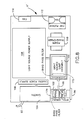
- Figure 8 is a diagrammatical plan view of the interior construction of the console of Figure 7;
- Figure 9 is an enlarged longitudinal section through the socket of the monitor and the strain relief unit of the endoscope showing the interconnection between the two;
- Figure 10 is a similar section through an eyepiece showing the interconnection between the eyepiece and the strain relief portion of the endoscope;
- Figure 11 is a vertical section, taken along line II-II of Figure 10, showing the spring detent for holding the strain relief unit in position;
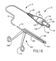
- Figure 12 is a perspective view of one of the endoscopes with a general purpose rigid examining tip on the distal end;
- Figure 13 is an enlarged longitudinal section, taken along line 13-13 of Figure 12, showing details of the end construction;
- Figure 14 is a perspective view of one of the endoscopes, this endoscope being similar to the one shown in Figure 12 but which has a stainless steel sheath on the distal end which may be either rigid or maleable;
- Figure 15 is a perspective view of one of the endoscopes, this one being similar to the one shown in Figures 12 and 14 but having an optical probe at the distal end of the endoscope; and
- Figure 16 is a perspective view of one of the endoscopes, similar to that shown in Figures 12,14 and 15, but having the distal end in a protective tube attached to grasping jaws of a pair of forceps.
- As shown in Figure 1, a sterilizable small diameter endoscope C includes a
cable assembly 10 which is provided at its distal end with alens 12 and at its proximate end with a coupling means 14. Turning to Figure 4, an enlarged cross-section ofcable assembly 10 is shown. At the centre of the cable is a coherent fibre-optical bundle 16. A tubularinner cover 18 extends around coherentoptical bundle 16 at each end and may be formed of a heat shrinkable Teflon (trade mark) of PVC material which extends along the coherent optical bundle from the distal end to the proximate end. Placed aroundinner covering 18 is a plurality of light carryingbundles 20 which are made up of individual fibres which do not have to be coherent. These bundles are for transmitting light from a suitable light source to the body cavity. Alternatively,bundle 20 may be replaced with a single flexible glass fibre. Anouter cover 22 extends around thespaced light bundles 20, as shown and may also be constructed of a heat shrinkable Teflon (trade mark) material which extends from the distal end ofcable assembly 10 to a position adjacent coupling means 14. The coupling means 14 is located at the proximate end ofouter cover 22 and includes alongitudinal groove 24 for alignment with a mating rib in a viewing means or in a strain relieve unit for connection to a viewing means. It can be made of any suitable material, such as anodized aluminium or a machinable grade of plastics, such as Bakelite (trade mark). - A
strain relief unit 11 is also illustrated in Figure 1 which can be used to connect the endoscope either to a console or to an eyepiece, as will be more fully explained below. Thestrain relief unit 11 has acylindrical body 26 having a fist taperedsection 28 and a second smallertapered section 30, as shown. The secondtapered section 30 terminates at its distal end in asocket 32 having alongitudinal rib 34 alignable withgroove 24 and held in place by lockingnut 36. The other end ofstrain relief unit 11 has amale connector 38 which is receivable in a console or an emergency use eyepiece, as will be described more fully below. By having thestrain relief unit 11 removable from endoscope C, it is possible to withdraw a trochar through which the endoscope may extend, also as explained below. - In addition, the endoscope can be connected to a eyepiece E as shown in Figure 2. The eyepiece E has a coupling means identical to that of
strain relief unit 11 so that it can be coupled to endoscope C. It has a socket 32ʹ with a longitudinal rib 34ʹ which is alignable with thegroove 24 of coupling means 14. Thus, the coupling means can be slid into the socket as best seen in Figure 2 and held in position by threaded lockingnut 36. The proximate end of coupling means 14 and the fibres are flat and polished so as to come into contiguous face-to-face contact with a rod lens 40 for transmitting the light from the coherent fibre bundle to the user's eye which is held against theocular face 42. The alignment of groove 32ʹ with rib 34ʹ ensures that the image being transmitted by the coherentoptical bundle 16 is in proper orientation with respect to lens 40 of eyepieceE. Light fibres 44 surround lens 40 and extend to afixture 46 to which a suitable light source can be attached for illuminating the body cavity by transmitting light alongfibres 44 and light bundles 20. - Because coupling means 14 has a diameter no larger than that of
outer cover 22, it can be used in a more versatile manner than heretofore possible. Figure 3 shows atrochar 50 which is illustrated as being inserted through thewall 52 of a body member and into abody cavity 54. The trochar has afirst lumen 56 through which the endoscope C extends into thebody cavity 54. Asecond lumen 58 is provided for any one of a number of purposes, such as for irrigation or treatment within thebody cavity 54. As is well known, trochars of this type may have more than two lumens, depending on their intended use. - After the procedure is completed through
lumen 58, it may be desirable to removetrochar 50 while leaving endoscope C in place for further viewing. This is possible using either the eyepiece of Figure 2 or the video console of Figure 3. - If an eyepiece E is used, such as one of the form shown in Figure 2, it can be removed by removing locking
nut 36 and sliding the coupling means 14 of the endoscope out of socket 32ʹ. Since the coupling means 14 is no larger in diameter thanouter cover 22, the trochar can be slid to the right, as viewed in Figure 3, while leaving endoscope C in place. After removal oftrochar 50, the eyepiece E can be reconnected to the coupling means 14, as previously described. The surgeon can then resume his viewing of the body cavity, as required. - Conveniently, the endoscope can also be used with a video console V, of the type shown in Figure 3. This console includes a
video screen 60. The coupling means 14 of endoscope C is receivable in asocket 62 which is connected to acamera 64 bysuitable optics 66 which includes a continuous focus zoom lens for transmitting the image tocamera 64. A light source (not shown) is provided and is connected tooptics 66 bylight cable 70. It is contemplated that endoscopes of different diameters may be used for different purposes. Thus,socket 62 can be provided in adisc 72 which is mounted for rotation on the video console V about anaxis 74 and is provided with a plurality of other sockets, such assockets socket 62, so as to be properly aligned with theoptics 64. - An important advantage is that when a
cable assembly 10 of the endoscop becomes damaged and no longer usable, it can be replaced with another one without having to replace a corresponding eyepiece. Furthermore, the endoscope can be made to be moisture-impervious so that it can be easily sterilized for re-use. When used with a console, the sterility of the operating environment can be maintained since the surgeon does not need to put the eyepiece against his face. Furthermore, when the device is used with the video monitor V, should there be a power interruption or should the video camera or monitor malfunction, it is merely necessary to slip the coupling means 14 of the endoscope out of its socket, such assocket 62, and attach a sterilized eyepiece E, which would be provided to the surgeon, so that we can continue with the operation or procedure with minimal interruption. - In another arrangement, shown in Figure 5, endoscope C extends through a
maleable sheath 82 which extends through abody canal 84 and is conformed to the shape of the canal. In addition to endoscope C, thesheath 82 may include alaser fibre 86 for phototherapy or photocoagulation treatment within the body cavity into which the sheath and endoscope extend. Additionally, it may include apassageway 88 for irrigation or suction. - A video console Vʹ is shown in Figure 7 which is specifically constructed for use with the strain relief unit U which couples endoscope C to the console. In this arrangement, a
video monitor 90 is provided as a separate unit and is connected to the console by asignal transmitting cable 92. The console Vʹ has afront panel 94 which contains the controls for the monitor camera, light source and filters, as well as areceptacle 96 for receiving strain relief unit U. As best seen in Figure 8, thereceptacle 96 is connected by means of alight cable 98 to alight source 100. Thereceptacle 96 is also connected to anoptical assembly 102 which transmits the image from the cable tocamera 104 for transmission bycable 92 to themonitor 90. The camera is connected to acamera power supply 106 and the lamp assembly is powered through lightsource power supply 108. Asuitable power transformer 110 andfans - Returning now to Figure 1, the
male connector 38 carries anoptical bundle 116 through the centre thereof which aligns with theoptical bundle 16 in endoscope C atsocket 32 and is polished at both ends so that light will be transmitted from one bundle to the next. Aflat face 118 radiates outwardly fromconnector 38 to the peripheral surface ofcylindrical body 26. The ends of light transmittingfibres 120 are spaced around this face and also have polished ends, the opposite ends thereof being aligned with the ends oflight bundles 20 of endoscope C. Alignment pins 122 are provided on opposite side ofconnector 38 to align the light bundles and optical bundles with the corresponding light transmitting fibres within video console Vʹ. - Turning to Figure 9, it can be seen that within
receptacle 96 are spacedlight bundles 124 which align withlight bundles 120. These light bundles are fed throughlight cable 98 to lightsource lamp assembly 100. Thus it can be seen that the light will be transmitted via all these light bundles from the light source lamp source assembly to the end of endoscope C for illuminating the area to be viewed. The image will be transmitted through the optical bundles, as described, to theoptical assembly 102 andcamera 104. Conveniently,connector 38 has aperipheral recess 126 for receiving aspring detent 128 in thereceptacle 96 and thereby releasably holding the strain relief unit U in place insocket 129. - An eyepiece Eʹ as shown in Figures 10 and 11 can be connected to strain relief unit U as shown. The eyepiece includes a socket or
receptacle 130 in which themale connector 38 extends. The light bundle thereof is aligned withlens 132 whereby the image is projected throughglass window 134 onto the eye of the surgeon. The eyepiece Eʹ is also provided with alight fixture 136 through which a bundle of light transmittingfibres 138 extends and terminates in peripherally spaced positions around the fact of the eyepiece for alignment with the light bundles 120 of strain relief unit U. As best seen in Figure 11, aspring detent 140 extends into theperipheral groove 126 ofmale connector 38 and releasably holds the strain relief unit and eyepiece Eʹ together. - Another form of the endoscope is shown at Cʹ in Figures 12 to 16 and has an integral strain relief unit Uʹ. The length of this device is approximately 190.5 centimetres (75 inches) to 203 centimetres (80 inches) in length and is very flexible. The tapered section is capable of accepting endoscopes of different diameters in the distal end. Each endoscope in Figures 12,14,15 and 16 has a different tip. A
general purpose tip 142 is shown in Figure 12. This tip may be the same diameter as the endoscope or enlarged, as shown. The tip may include astainless steel jacket 144, as best seen in Figure 13, or it may not have a metal covering at all and be very flexible. As can be seen from Figure 13, within thejacket 144 isoptical bundle 16 having acover 18 and surrounded by spaced light bundles 20. Conveniently, alens 146 is provided at the end ofoptical bundle 16 for focussing an image of the site being investigated on to the end oflight bundle 16 for transmission to the viewing means. - In Figure 14 a long straight probe 148 is illustrated which may be a stainless steel jacket made of #304 tempered stainless steel. Also, #316, #316L and INCONEL 600 (trade mark) steel may be used. This device may be used for insertion into various body passageways which are relatively straight. Alternatively, a maleable jacket 150 (shown in dotted lines) may be used which can be conformed to the passageway through which it is to extend. Such usage of this device might be as an arthroscope and the maleable material may be sterling silver. With this device the surgeon can bend it to fit his needs to see a particular part of the joint in which it is used. After the procedure is completed, it can be straightened for use in the next succeeding case. In small joints, such as a finger joint, the device might be approximately 1.0 mm in diameter. If it is intended for use in examining an ankle joint it might be 2.0 mm in diameter. For still larger joints like a knee joint, it might be 3.5 mm to 5.0 mm in diameter, or possibly larger. The metal sleeve can be approximately 15 centimetres (6 inches) to 20 centimetres (8 inches) in length. In the maleable device, a maleable form of stainless steel might be used instead of sterling silver. A closely wound steel spring of appropriate length may be provided to slip over the maleable section to aid the surgeon to shape this section to desired configuration without crimping. This steel spring is them removed after shaping and set aside.
- If the device is used as a hysteroscope it might be made less than 1.0 mm in diameter. This size is selected to allow passage of the device into the cervical canal without dilating the cervix. If made this small, the endoscope can be passed into the cervix along with other devices such as a special fibre-optic, possible of 200 to 400 microns diameter, for transmitting laser energy for photocoagulation as previously discussed with respect to Figure 5. A channel for either suction or irrigation can be provided. With the maleable sheath, the device can be preformed to the shape of the particular uterine cavity in which it is being used.
- In the embodiment of Figure 15 an
optical probe 152 is illustrated which has arigid body portion 154 with ahand grip 156 and a curvedrigid probe 158 which allows the physician directional stability so that he can point the device wherever he wants it to look around other body portions. - A still further embodiment is shown in Figure 16 wherein the endoscope Cʹ extends into a protective
stainless steel housing 160 which is attached to the side of a pair offorcepts 162, such as a laryngeal grasping device which might be used to extract a fish bone from the larynx. The metal tube is welded or otherwise attached tolower jaw 164 of the instrument. Theupper jaw 166 can be moved relative tojaw 164 by squeezinghandles - It will be understood that other uses will become apparent to one skilled in the art in addition to those illustrated.
- With slight modification, the endoscopes described and the console can be used as a fluorescence detector and provide a means for not only detecting abnormal cells but also for treating the cells by phototherapy and measuring the effectiveness of that treatment. In this regard the patient is given a drug which has a particular affinity to the abnormal cells and which will fluoresce when exposed to light of a prederermined first frequency. This light frequency can be transmitted through special light fibres of the endoscope onto the tissue being examined. When fluorescence is viewed on the monitor or with the eyepiece, the surgeon will know that this is a site of abnormal cells. Light of a second frequency which will kill the cells can be directed down the light fibres or through a separate and additional light fibre. If even a third light channel is provided, to permit the use of other light frequencies, various quantitative measurements can be done through the endoscope. In some situations, strobed light may be used.
- One drug that has been found to be ideal for detecting abnormal calls, such as cancer cells, is a hematoporphyrin derivative (HPD). When exposed to a light frequency between 400 nm and 410 nm it will fluoresce to a salmon pink colour having a wavelength of 630 nm. If the tumour containing the drug is then exposed to an external laser frequency of 630 nm the cancer cell is destroyed with no harm to surrounding normal cells. This is referred to as HPD phototherapy. The cancer cells are destroyed because the 630 nm light causes a change in the oxygen in the cell to a form called "singlet oxygen" which is toxic to the cell. The oxygen content of the cell can be monitored by utilizing laser light to measure absorption spectra and by a spectrophotometer. Turning to Figure 8, it will be apparent that the lamp and light
source lamp assembly 100 can be changed, such as to a halogen light which provides a frequency in the visible range, or alternatively aband pass filter 172 can be inserted which allows transmission of only those light rays which fall within the desired frequency. The fluorescing cells will then transmit light through the optical assembly tocamera 104. Again, a secondband pass filter 174 can be inserted between the optical assembly and the camera which allows transmission only of the reflective fluorescent light in the range of 630 nm. Also, various electronic equipment, known in the art for image processing and image enhancement to increase the brilliance of such an image, can be utilized to make the fluorescing cells clearly visible to the physician on thevideo monitor 90. Furthermore,band pass filter 172 can be replaced by other filters, such as to permit transmission of light having a different frequency from the range 630 nm. The two frequencies of 410 nm and 630 nm can be strobed so that they are alternately sent along the light fibres for fluorescence and for killing the cells, respectively. - Although a particular photochemical material and light range has been described, it will be understood that other photochemical materials may give off other light frequencies which could be anywhere from the infrared frequency through the visible frequency to the ultraviolet frequency. In addition to a halogen light source, a mercury vapour light source or a xenon light source could be used with the band pass filters.
- In addition, the endoscope can be changed to provide fibres which are particularly effective for transmitting light in the 400 nm to 410 nm frequency range. Such fibres are available through Gallileo Electro-Optics Company of Sturbridge, Massachusetts, U.S.A. and other manufacturers. Another fluorescence detector compound which has been found effective is Rhodamine-123.
- Form the foregoing, it will be apparent that an endoscope has been described which has great versatility in that it may be used with either a substantially standard eyepiece or with a video camera and monitor. The endoscopes described can be provided in different sizes when used with a video monitor, which may contain a plurality of sockets for alignment with the optical means of the video camera for connection with a endoscope of the selected size. Furthermore, the endoscope can be used within the lumen of a trochar or operating channel of a larger endoscope and, since the eyepiece is removable, the trochar or larger endoscope can be removed without removing the basic endoscope and the eyepiece can then be replaced for further viewing. The endoscope can be easily replaced should it become damaged, without replacement of the expensive viewing means. Also, the sterility of the endoscope can be maintained when used with the console, which permits its use with a lower risk of infection. Furthermore, no separate light cable is needed.
- The device can also be used for detection and treatment of cancer cells or other abnormal cells by using it to excite a fluorescent dye in the abnormal cell by excitation with a selected laser light. The fluorescence will give off its own light which can be detected and displayed on the video monitor whereupon a laser light of the same frequency can be transmitted back to the cell and used to convert the oxygen in the cell to singlet oxygen thereby destroying the cell. The effect of the phototherapy can be monitored by photometric means.
- From the foregoing it can be seen that a method of using a sterilized endoscope for viewing and/or treatment within body cavities has also been described which includes inserting the distal end of the endoscope into a body cavity, attaching a first removable optic means to the coupling means to view the body cavity, disconnecting the first removable optic means from the coupling means, and attaching a second removable optic means to the coupling means to view the body cavity.
Claims (24)
a coherent fibre optical bundle (16) having a micro-thin diameter and extending from said distal end to a point adjacent said proximate end and having a planar surface at its proximate end;
a plurality of light transmitting fibres (20) spaced around said optical bundle (16);
a tubular outer cover (22) extending over said fibres (20) to hold them in place, said outer cover (22) extending from said distal end to a point spaced from said proximate end;
optical lens means (12) at said distal end of said optical bundle (16) to focus an image of a portion of the cavity on said distal end of said optical bundle (16) for transmission through said optical bundle (16); and
a coupling means (14) for removably connecting the endoscope to a viewing means (E,V) in fixed angular relationship, the coupling means being fixedly attached at said proximate end of said endoscope and having a diameter no larger than the diameter of said outer covering (22) so that the endoscope can pass completely through a trochar lumen (56) or operating channel of a larger endoscope.
a bundle of optical fibres (116) extending longitudinally therethrough to each end which are alignable with light fibres (16) in said endoscope; and
alignment pins (122) adjacent said male connector (38) to align said bundle of optical fibres (116) in said unit with the viewing means (E,V).
an optical assembly (102) including a receptacle (96);
a light source (100;
light fibres (98) for transmitting light from said light source (100) to points spaced around said receptacle (96);
a camera (104) aligned with said optical assembly (102) for receiving images from the optical bundle (16) of the endoscope; and
a video monitor (90) connected to said camera (104) for displaying the images.
a first band pass filter (172) between said light source (100) and said light fibres (98) to allow transmission of a selected light frequency through said endoscope to cause fluorescence of cells to be treated; and
a second band pass filter (174) between said optical assembly (102) and said cameral (104) to allow transmissions of the fluorescence frequency only to the camera (104) for display by said video monitor (90).
inserting the distal end (12) into the body cavity (54,84);
attaching a first removable optical viewing means (E,V) to the coupling means (14) to view the body cavity (54,84);
disconnecting the first removable optical viewing mkeans (E,V) from the coupling means (14); and
attaching a second removable optical viewing means (E,V) to the coupling means (14) to view the body cavityt (54,84).
inserting a trochar (52) into the body cavity (54,84);
inserting the endoscope into the body cavity through the lumen (56) of the trochar (50);
attaching a removable optical viewing means (V) to the coupling means (14);
viewing the body cavity (54,84) through the endoscope via the optical viewing means (V);
disconnecting the optical viewing means (V) from the coupling means (14);
removing the trochar (50) over the coupling means (14) while leaving the endoscope in place;
re-attaching the optical viewing means (V) to the coupling means (14); and
resuming the viewing of the body cavity (54,84) through the endoscope via the optical viewing means (V).
giving the patient a fluorescent drug which localizes in the abnormal cells;
irradiating the body area containing the abnormal cells with a light of a first frequency which will cause the abnormal cells to fluoresce; and
treating the abnormal cells by irradiating them with laser light of a second frequency to destroy the abnormal cells.
said drug is a derivative of hematoporphyrin;
said first light frequency is in the range of 400 nm to 410 nm; and
said second light frequency is 630 nm.
Applications Claiming Priority (4)
| Application Number | Priority Date | Filing Date | Title |
|---|---|---|---|
| US07/018,630 US4736733A (en) | 1987-02-25 | 1987-02-25 | Endoscope with removable eyepiece |
| US18630 | 1987-02-25 | ||
| US07/036,553 US4782819A (en) | 1987-02-25 | 1987-04-09 | Optical catheter |
| US36553 | 1987-04-09 |
Publications (3)
| Publication Number | Publication Date |
|---|---|
| EP0280397A2 true EP0280397A2 (en) | 1988-08-31 |
| EP0280397A3 EP0280397A3 (en) | 1988-12-28 |
| EP0280397B1 EP0280397B1 (en) | 1993-06-16 |
Family
ID=26691319
Family Applications (1)
| Application Number | Title | Priority Date | Filing Date |
|---|---|---|---|
| EP88300562A Expired - Lifetime EP0280397B1 (en) | 1987-02-25 | 1988-01-25 | Endoscope |
Country Status (5)
| Country | Link |
|---|---|
| US (1) | US4782819A (en) |
| EP (1) | EP0280397B1 (en) |
| JP (1) | JPS63272320A (en) |
| CA (1) | CA1287541C (en) |
| DE (1) | DE3881717T2 (en) |
Cited By (20)
| Publication number | Priority date | Publication date | Assignee | Title |
|---|---|---|---|---|
| EP0335523A1 (en) * | 1988-03-31 | 1989-10-04 | BAXTER INTERNATIONAL INC. (a Delaware corporation) | Endoscope coupler device |
| WO1990007299A1 (en) * | 1988-12-28 | 1990-07-12 | Adair Edwin Lloyd | Method and apparatus for cervical videoscopy |
| EP0389453A1 (en) * | 1989-03-22 | 1990-09-26 | Gualtiero Cozzi | Fibre optical dental endoscope |
| WO1990013254A1 (en) * | 1989-05-05 | 1990-11-15 | Aesculap Ag | Coupling for an electronic camera and for an optical fibre waveguide |
| WO1992015238A1 (en) * | 1991-03-06 | 1992-09-17 | Omega Universal Limited | An improved micro-endoscope |
| EP0600413A3 (en) * | 1992-11-30 | 1995-04-05 | Neuro Navigational Corp | Neuro endoscope for shunt. |
| EP0627074A4 (en) * | 1992-11-25 | 1997-08-06 | Tufts College | Fiber optic array sensors and methods for concurrently visualizing and chemically detecting multiple analytes in a fluid. |
| US6332092B1 (en) | 1998-07-08 | 2001-12-18 | Lifespex, Incorporated | Optical probe having and methods for uniform light irradiation and/or light collection over a volume |
| WO2002074339A1 (en) * | 2001-03-16 | 2002-09-26 | University Of Utah Research Foundation | Deveice and method for the photodynamic diagnosis of tumor tissue |
| US6487440B2 (en) | 1998-07-08 | 2002-11-26 | Lifespex, Inc. | Optical probe having and methods for difuse and uniform light irradiation |
| WO2004100789A1 (en) * | 2003-05-14 | 2004-11-25 | Spectracure Ab | System and method for therapy and diagnosis comprising optical components for distribution of radiation |
| WO2004101069A1 (en) * | 2003-05-14 | 2004-11-25 | Spectracure Ab | System and method for therapy and diagnosis comprising translatory distributor for distribution of radiation |
| WO2004100761A3 (en) * | 2003-05-14 | 2005-01-20 | Spectracure Ab | System and method for therapy and diagnosis comprising in combination non-mechanical and mechanical distributors for distribution of radiation |
| WO2008124492A1 (en) * | 2007-04-10 | 2008-10-16 | Boston Scientific Limited | Apparatus and method for treating the inside of an eye |
| AU2008200058B2 (en) * | 2001-03-16 | 2009-12-24 | University Of Utah Research Foundation | Device and method for the photodynamic diagnosis of tumor tissue |
| WO2010098807A1 (en) * | 2009-02-24 | 2010-09-02 | Visionscope Technologies, Llc | Disposable sheath for use with an imaging system |
| US9532772B2 (en) | 2006-03-24 | 2017-01-03 | Occlutech Holding Ag | Occlusion device and method for its manufacture |
| KR20170122323A (en) * | 2016-04-26 | 2017-11-06 | (주)인투케어 | Laser Surgical Instrument |
| US10595710B2 (en) | 2001-10-19 | 2020-03-24 | Visionscope Technologies Llc | Portable imaging system employing a miniature endoscope |
| US11484189B2 (en) | 2001-10-19 | 2022-11-01 | Visionscope Technologies Llc | Portable imaging system employing a miniature endoscope |
Families Citing this family (170)
| Publication number | Priority date | Publication date | Assignee | Title |
|---|---|---|---|---|
| US5116317A (en) * | 1988-06-16 | 1992-05-26 | Optimed Technologies, Inc. | Angioplasty catheter with integral fiber optic assembly |
| US5101807A (en) * | 1989-02-10 | 1992-04-07 | Olympus Optical Co., Ltd. | Endoscope connecting apparatus |
| US5152760A (en) * | 1989-03-17 | 1992-10-06 | The General Hospital Corporation | Non-invasive sclerostomy |
| NL8902307A (en) * | 1989-09-14 | 1991-04-02 | Cordis Europ | CATHETER. |
| CA2035488A1 (en) * | 1990-02-14 | 1991-08-15 | Edwin L. Adair | Endotracheal tube intubation assist device |
| US5109830A (en) * | 1990-04-10 | 1992-05-05 | Candela Laser Corporation | Apparatus for navigation of body cavities |
| US5159920A (en) * | 1990-06-18 | 1992-11-03 | Mentor Corporation | Scope and stent system |
| US5292362A (en) * | 1990-07-27 | 1994-03-08 | The Trustees Of Columbia University In The City Of New York | Tissue bonding and sealing composition and method of using the same |
| US5209776A (en) * | 1990-07-27 | 1993-05-11 | The Trustees Of Columbia University In The City Of New York | Tissue bonding and sealing composition and method of using the same |
| US5323767A (en) * | 1991-02-04 | 1994-06-28 | Citation Medical Corporation | Portable arthroscope with periscope optics |
| US5188093A (en) * | 1991-02-04 | 1993-02-23 | Citation Medical Corporation | Portable arthroscope with periscope optics |
| US5190028A (en) * | 1991-02-04 | 1993-03-02 | Citation Medical Corporation | Method for manufacturing a disposable arthroscopic probe |
| US5329936A (en) * | 1991-02-04 | 1994-07-19 | Citation Medical Corporation | Portable arthroscope with periscope optics |
| US5435307A (en) * | 1991-03-29 | 1995-07-25 | The United States Of America As Represented By The Secretary Of The Department Of Health And Human Services | Surface fluorescent monitor |
| GB2258928B (en) * | 1991-08-16 | 1994-09-28 | Keymed | A borescope |
| DE4207092A1 (en) * | 1992-03-06 | 1993-09-16 | Schott Glaswerke | ENDOSCOPE |
| US5857996A (en) | 1992-07-06 | 1999-01-12 | Catheter Imaging Systems | Method of epidermal surgery |
| US5351678A (en) * | 1992-09-01 | 1994-10-04 | Citation Medical Corporation | Endoscope scope assembly for full hemisphere view |
| USD349340S (en) | 1992-10-19 | 1994-08-02 | Catheter Imaging Systems | Catheter imaging light source |
| US5667478A (en) * | 1992-11-06 | 1997-09-16 | Clarus Medical Systems, Inc. | Surgical instrument with stick-on fiber-optic viewing system and method of using |
| US6063024A (en) * | 1992-11-19 | 2000-05-16 | Scalar Corp. | Observation apparatus |
| US5354518A (en) * | 1993-02-11 | 1994-10-11 | Sherwood Medical Company | Method for manufacturing a fiberscopic catheter |
| US5507772A (en) * | 1993-05-25 | 1996-04-16 | Depuy Inc. | Cleanable, inspectable, and replaceable surgical instrument |
| US5456245A (en) * | 1993-09-20 | 1995-10-10 | Sofamor Danek Properties, Inc. | Flexible endoscope probe and method of manufacture |
| US5478338A (en) * | 1993-09-24 | 1995-12-26 | Reynard; Michael | Fiber optic sleeve for surgical instruments |
| US5667472A (en) * | 1994-03-18 | 1997-09-16 | Clarus Medical Systems, Inc. | Surgical instrument and method for use with a viewing system |
| US5450857A (en) * | 1994-05-19 | 1995-09-19 | Board Of Regents, The University Of Texas System | Method for the diagnosis of cervical changes |
| AU738235B2 (en) * | 1994-05-19 | 2001-09-13 | Board Of Regents, The University Of Texas System | Instrument for the diagnosis of cervical changes |
| USD362908S (en) | 1994-05-20 | 1995-10-03 | Depuy Inc. | Endoscopic surgical instrument handle |
| US5456681A (en) * | 1994-06-03 | 1995-10-10 | Hajjar; John H. | Laser therapy system |
| US5517997A (en) * | 1994-09-15 | 1996-05-21 | Gabriel Medical, Inc. | Transillumination of body members for protection during body invasive procedures |
| US5716320A (en) * | 1994-10-31 | 1998-02-10 | Buttermore; William J. | Illuminated intraocular surgical instrument |
| US5857961A (en) * | 1995-06-07 | 1999-01-12 | Clarus Medical Systems, Inc. | Surgical instrument for use with a viewing system |
| US5611797A (en) * | 1995-07-26 | 1997-03-18 | Virginia C. George | Combination handpiece and surgical laser tool |
| US5840017A (en) * | 1995-08-03 | 1998-11-24 | Asahi Kogaku Kogyo Kabushiki Kaisha | Endoscope system |
| US6117068A (en) * | 1995-10-19 | 2000-09-12 | Elite Genetics, Inc | Artificial insemination system |
| US5860953A (en) * | 1995-11-21 | 1999-01-19 | Catheter Imaging Systems, Inc. | Steerable catheter having disposable module and sterilizable handle and method of connecting same |
| US6007531A (en) * | 1995-11-21 | 1999-12-28 | Catheter Imaging Systems, Inc. | Steerable catheter having disposable module and sterilizable handle and method of connecting same |
| USD398986S (en) | 1996-01-16 | 1998-09-29 | Catheter Imaging Systems, Inc. | Handle interface for steerable catheter |
| USD405881S (en) | 1996-01-16 | 1999-02-16 | Catheter Imaging Systems, Inc. | Handle for steerable catheter |
| US5651783A (en) * | 1995-12-20 | 1997-07-29 | Reynard; Michael | Fiber optic sleeve for surgical instruments |
| US5967973A (en) | 1996-04-26 | 1999-10-19 | United States Surgical | Surgical retractor and method of surgery |
| US6129662A (en) * | 1996-06-03 | 2000-10-10 | Cogent Light Technologies, Inc. | Surgical tool with surgical field illuminator |
| US5954713A (en) | 1996-07-12 | 1999-09-21 | Newman; Fredric A. | Endarterectomy surgical instruments and procedure |
| US20050182297A1 (en) * | 1996-10-04 | 2005-08-18 | Dietrich Gravenstein | Imaging scope |
| US6322498B1 (en) * | 1996-10-04 | 2001-11-27 | University Of Florida | Imaging scope |
| AU5431898A (en) * | 1996-11-21 | 1998-06-10 | Boston Scientific Corporation | Mucosal ablation using light |
| US5941816A (en) * | 1997-04-15 | 1999-08-24 | Clarus Medical Systems, Inc. | Viewing system with adapter handle for medical breathing tubes |
| US7505807B1 (en) | 1997-05-15 | 2009-03-17 | Regents Of The University Of Minnesota | Magnetic resonance apparatus for use with active electrode and drug deliver catheter |
| US6096065A (en) * | 1997-09-29 | 2000-08-01 | Boston Scientific Corporation | Sheath for tissue spectroscopy |
| US6086528A (en) * | 1997-09-11 | 2000-07-11 | Adair; Edwin L. | Surgical devices with removable imaging capability and methods of employing same |
| US5921917A (en) * | 1997-10-20 | 1999-07-13 | Clarus Medical Systems, Inc. | Hand-held viewing system with removable sheath |
| US6605751B1 (en) | 1997-11-14 | 2003-08-12 | Acrymed | Silver-containing compositions, devices and methods for making |
| US6368318B1 (en) * | 1998-01-23 | 2002-04-09 | The Regents Of The University Of California | Opto-acoustic recanilization delivery system |
| WO1999037213A1 (en) | 1998-01-23 | 1999-07-29 | United States Surgical Corporation | Surgical instrument |
| US6200263B1 (en) | 1998-01-23 | 2001-03-13 | United States Surgical Corporation | Surgical instrument holder |
| US5951463A (en) * | 1998-03-18 | 1999-09-14 | Clarus Medical Systems, Inc. | Hand-held endoscopic viewing system |
| US6004262A (en) * | 1998-05-04 | 1999-12-21 | Ad-Tech Medical Instrument Corp. | Visually-positioned electrical monitoring apparatus |
| US6190040B1 (en) * | 1999-05-10 | 2001-02-20 | Sensarray Corporation | Apparatus for sensing temperature on a substrate in an integrated circuit fabrication tool |
| EP1244476B1 (en) | 1999-12-30 | 2006-05-31 | Acrymed | Methods and compositions for improved delivery devices |
| US7867186B2 (en) | 2002-04-08 | 2011-01-11 | Glaukos Corporation | Devices and methods for treatment of ocular disorders |
| US6638239B1 (en) | 2000-04-14 | 2003-10-28 | Glaukos Corporation | Apparatus and method for treating glaucoma |
| US6733441B2 (en) * | 2000-05-11 | 2004-05-11 | Olympus Corporation | Endoscope device |
| WO2001089598A2 (en) * | 2000-05-19 | 2001-11-29 | C.R. Bard, Inc. | Guidewire with viewing capability |
| JP2002065577A (en) * | 2000-08-28 | 2002-03-05 | Olympus Optical Co Ltd | Endoscope |
| US6461569B1 (en) * | 2000-11-15 | 2002-10-08 | Ethicon Endo Surgery, Inc. | Method and apparatus for ultraviolet radiation catheter sterilization system |
| US6826424B1 (en) | 2000-12-19 | 2004-11-30 | Haishan Zeng | Methods and apparatus for fluorescence and reflectance imaging and spectroscopy and for contemporaneous measurements of electromagnetic radiation with multiple measuring devices |
| JP2004524076A (en) * | 2001-01-11 | 2004-08-12 | ギブン・イメージング・リミテツド | Apparatus and system for in vivo procedures |
| DE10107586A1 (en) * | 2001-02-10 | 2002-08-14 | Biotronik Mess & Therapieg | Endoscopic catheter |
| US6743221B1 (en) * | 2001-03-13 | 2004-06-01 | James L. Hobart | Laser system and method for treatment of biological tissues |
| EP2263621B1 (en) | 2001-04-07 | 2015-05-20 | Glaukos Corporation | System for treating ocular disorders |
| US7992573B2 (en) * | 2001-06-19 | 2011-08-09 | The Trustees Of The University Of Pennsylvania | Optically guided system for precise placement of a medical catheter in a patient |
| JP4842509B2 (en) | 2001-06-19 | 2011-12-21 | ザ・トラステイーズ・オブ・ザ・ユニバーシテイ・オブ・ペンシルベニア | Optical guidance system for placement of invasive catheters |
| US7137949B2 (en) * | 2001-07-13 | 2006-11-21 | United States Surgical Corporation | Surgical instrument |
| JP4416990B2 (en) | 2001-08-06 | 2010-02-17 | ギブン イメージング リミテッド | System for operating a device in vivo |
| HU224941B1 (en) * | 2001-08-10 | 2006-04-28 | Bgi Innovacios Kft | Phototerapy apparatus |
| US7331984B2 (en) | 2001-08-28 | 2008-02-19 | Glaukos Corporation | Glaucoma stent for treating glaucoma and methods of use |
| US20040082863A1 (en) * | 2002-03-15 | 2004-04-29 | Mcgreevy James | Device and method for the photodynamic diagnosis of tumor tissue |
| CN1678277B (en) | 2002-07-29 | 2010-05-05 | 艾克里麦德公司 | Methods and compositions for treating skin diseases |
| AU2003279097A1 (en) * | 2002-09-30 | 2004-04-19 | Vanderbilt University | Optical apparatus for guided liver tumor treatment and methods |
| DE10307903A1 (en) * | 2003-02-18 | 2004-09-02 | Karl Storz Gmbh & Co. Kg | Method for mounting an endoscope |
| WO2004096008A2 (en) * | 2003-05-01 | 2004-11-11 | Given Imaging Ltd. | Panoramic field of view imaging device |
| FR2860135B1 (en) * | 2003-09-30 | 2005-12-02 | Alain Queyroux | FIBROSCOPE WITH SEPARABLE INSERTION TUBE |
| WO2005034754A1 (en) * | 2003-10-15 | 2005-04-21 | The University Of British Columbia | Methods and apparatus for urodynamic analysis |
| US8260389B2 (en) * | 2003-10-15 | 2012-09-04 | Hegln (Dalian) Pharmaceuticals, Inc. | Bladder function monitoring methods, apparatuses, media and signals |
| ES2552252T3 (en) | 2004-03-23 | 2015-11-26 | Boston Scientific Limited | Live View System |
| US7922654B2 (en) | 2004-08-09 | 2011-04-12 | Boston Scientific Scimed, Inc. | Fiber optic imaging catheter |
| US11832793B2 (en) | 2004-03-23 | 2023-12-05 | Boston Scientific Scimed, Inc. | Vivo visualization system |
| BE1015965A6 (en) * | 2004-03-31 | 2005-12-06 | Const Electr Schreder | Method and device phototherapy. |
| US8177760B2 (en) | 2004-05-12 | 2012-05-15 | C. R. Bard, Inc. | Valved connector |
| US20050278010A1 (en) * | 2004-05-27 | 2005-12-15 | Scimed Life Systems, Inc. | Stent delivery system with imaging capability |
| US7336833B2 (en) * | 2004-06-30 | 2008-02-26 | Given Imaging, Ltd. | Device, system, and method for reducing image data captured in-vivo |
| US7643865B2 (en) * | 2004-06-30 | 2010-01-05 | Given Imaging Ltd. | Autonomous in-vivo device |
| CN102783499A (en) | 2004-07-30 | 2012-11-21 | 金伯利-克拉克环球有限公司 | Antimicrobial devices and compositions |
| NZ552928A (en) | 2004-07-30 | 2011-05-27 | Acrymed Inc | Antimicrobial silver compositions |
| US8361553B2 (en) | 2004-07-30 | 2013-01-29 | Kimberly-Clark Worldwide, Inc. | Methods and compositions for metal nanoparticle treated surfaces |
| US9289378B2 (en) | 2004-09-20 | 2016-03-22 | Avent, Inc. | Antimicrobial amorphous compositions |
| US20080039715A1 (en) * | 2004-11-04 | 2008-02-14 | Wilson David F | Three-dimensional optical guidance for catheter placement |
| WO2006065271A2 (en) * | 2004-12-15 | 2006-06-22 | Embo-Optics, Llc | Point of infusion lighting device |
| US8109981B2 (en) | 2005-01-25 | 2012-02-07 | Valam Corporation | Optical therapies and devices |
| US9675235B2 (en) * | 2005-03-21 | 2017-06-13 | Jonas V. Lieponis | Multi-purpose surgical instrument with removable component |
| US20060211918A1 (en) * | 2005-03-21 | 2006-09-21 | Lieponis Jonas V | Surgical instrument with integral optical system |
| US20060217593A1 (en) * | 2005-03-24 | 2006-09-28 | Zvika Gilad | Device, system and method of panoramic multiple field of view imaging |
| WO2006122303A2 (en) * | 2005-05-11 | 2006-11-16 | Boston Scientific Limited | Visualization system |
| US7553278B2 (en) * | 2005-06-01 | 2009-06-30 | Cannuflow, Inc. | Protective cap for arthroscopic instruments |
| US20070073160A1 (en) | 2005-09-13 | 2007-03-29 | Children's Medical Center Corporation | Light-guided transluminal catheter |
| US8954134B2 (en) | 2005-09-13 | 2015-02-10 | Children's Medical Center Corporation | Light-guided transluminal catheter |
| US7901441B2 (en) | 2005-10-18 | 2011-03-08 | Boston Scientific Scimed, Inc. | Method of using an imaging catheter to conduct photodynamic procedures |
| US7753902B1 (en) * | 2005-11-17 | 2010-07-13 | Hebah Noshy Mansour | Methods and devices for tissue monitoring |
| US8293965B2 (en) | 2006-04-28 | 2012-10-23 | Kimberly-Clark Worldwide, Inc. | Antimicrobial site dressings |
| CA2668954C (en) | 2006-11-10 | 2020-09-08 | Glaukos Corporation | Uveoscleral shunt and methods for implanting same |
| TW200824643A (en) * | 2006-12-13 | 2008-06-16 | Chieh-Hsiao Chen | Guiding stylet apparatus |
| US20080262413A1 (en) * | 2007-04-19 | 2008-10-23 | Ladizinsky Daniel A | Method For Supplying Oxygenated Water To Promote Internal Healing |
| WO2009012406A1 (en) * | 2007-07-17 | 2009-01-22 | Transcend Medical, Inc. | Ocular implant with hydrogel expansion capabilities reference to priority document |
| US9339174B2 (en) | 2007-07-18 | 2016-05-17 | Given Imaging Ltd | Device and method for viewing a body lumen |
| US8888683B2 (en) * | 2008-01-28 | 2014-11-18 | Mauricio Mejia | Modifications in endoscope apparatus, using fluid and gas dynamics, and methods for improving visibility during endoscopy |
| US9095298B2 (en) | 2008-06-23 | 2015-08-04 | Intubrite, Llc | Adjustable display mechanism and method |
| US8257250B2 (en) * | 2008-06-23 | 2012-09-04 | Intubrite, Llc | Laryngoscope and method of use |
| US8152719B2 (en) * | 2008-06-23 | 2012-04-10 | Intubrite, Llc | Laryngoscope and method of use |
| US20090318768A1 (en) * | 2008-06-23 | 2009-12-24 | Tenger James P | Laryngoscope and Method of Use |
| US8012087B2 (en) * | 2008-06-23 | 2011-09-06 | Intubrite, Llc | Laryngoscope blade and method of use |
| US8968186B2 (en) | 2008-06-23 | 2015-03-03 | Intubrite, Llc | Handle for fiber optic device |
| USD632787S1 (en) | 2009-11-03 | 2011-02-15 | Intubrite, Llc | Laryngoscope handle |
| US9072446B2 (en) | 2008-06-23 | 2015-07-07 | Intubrite, Llc | Laryngoscope and method of use |
| USRE48598E1 (en) | 2008-06-23 | 2021-06-22 | Salter Labs | Laryngoscope and method of use |
| WO2010014568A1 (en) * | 2008-07-28 | 2010-02-04 | William Beaumont Hospital | Multiple port introducer for thrombolysis |
| USD691268S1 (en) * | 2009-01-07 | 2013-10-08 | Salutaris Medical Devices, Inc. | Fixed-shape cannula for posterior delivery of radiation to eye |
| USD691267S1 (en) * | 2009-01-07 | 2013-10-08 | Salutaris Medical Devices, Inc. | Fixed-shape cannula for posterior delivery of radiation to eye |
| USD691270S1 (en) * | 2009-01-07 | 2013-10-08 | Salutaris Medical Devices, Inc. | Fixed-shape cannula for posterior delivery of radiation to an eye |
| USD691269S1 (en) * | 2009-01-07 | 2013-10-08 | Salutaris Medical Devices, Inc. | Fixed-shape cannula for posterior delivery of radiation to an eye |
| USD609808S1 (en) | 2009-02-10 | 2010-02-09 | Intubrite, Llc | Laryngoscope blade |
| USD608889S1 (en) | 2009-02-10 | 2010-01-26 | Intubrite, Llc | Laryngoscope |
| USD611598S1 (en) | 2009-02-10 | 2010-03-09 | Intubrite, Llc | Laryngoscope handle |
| WO2010115101A1 (en) | 2009-04-03 | 2010-10-07 | Transcend Medical, Inc. | Ocular implant delivery systems and methods |
| USD630738S1 (en) | 2009-12-21 | 2011-01-11 | Intubrite, Llc | Laryngoscope blade |
| USD630737S1 (en) | 2009-12-21 | 2011-01-11 | Intubrite, Llc | Laryngoscope blade |
| USD630739S1 (en) | 2009-12-21 | 2011-01-11 | Intubrite, Llc | Laryngoscope blade |
| USD634008S1 (en) | 2009-12-21 | 2011-03-08 | Intubrite, Llc | Laryngoscope blade |
| USD630745S1 (en) | 2009-12-23 | 2011-01-11 | Intubrite, Llc | Laryngoscope blade |
| USD630740S1 (en) | 2009-12-23 | 2011-01-11 | Intubrite, Llc | Laryngoscope blade |
| USD630741S1 (en) | 2009-12-23 | 2011-01-11 | Intubrite, Llc | Laryngoscope blade |
| USD630743S1 (en) | 2009-12-23 | 2011-01-11 | Intubrite, Llc | Laryngoscope blade |
| USD630744S1 (en) | 2009-12-23 | 2011-01-11 | Intubrite, Llc | Laryngoscope blade |
| USD630742S1 (en) | 2009-12-23 | 2011-01-11 | Intubrite, Llc | Laryngoscope blade |
| US20110190748A1 (en) * | 2010-01-29 | 2011-08-04 | Arista Therapeutics, Inc. | Laparoscope for low laser level irradiation |
| US20110190747A1 (en) * | 2010-01-29 | 2011-08-04 | Arista Therapeutics, Inc. | Disposable led/laser catheter |
| US8920309B2 (en) * | 2010-03-12 | 2014-12-30 | Microline Surgical, Inc. | Picture in picture clip applier video system |
| EP2756792A1 (en) | 2010-09-08 | 2014-07-23 | Covidien LP | Catheter with imaging assembly |
| EP2654715B1 (en) | 2010-11-24 | 2017-01-25 | Dose Medical Corporation | Drug eluting ocular implant |
| US20130178703A1 (en) * | 2012-01-05 | 2013-07-11 | Gyrus Acmi, Inc. | Endoscope Shaft With Malleable Section |
| USD698441S1 (en) * | 2012-01-20 | 2014-01-28 | Olympus Corporation | Endoscope |
| USD737966S1 (en) | 2012-01-20 | 2015-09-01 | Olympus Corporation | Endoscope |
| JP6164207B2 (en) * | 2012-03-16 | 2017-07-19 | コニカミノルタ株式会社 | Fiberscope, insertion portion thereof, and endoscope system |
| JP6465490B2 (en) | 2012-03-26 | 2019-02-06 | グローコス コーポレーション | Implant delivery device |
| DE102012008970B3 (en) * | 2012-05-03 | 2013-06-27 | Joimax Gmbh | Surgical tooling |
| USD735343S1 (en) | 2012-09-07 | 2015-07-28 | Covidien Lp | Console |
| USD717340S1 (en) | 2012-09-07 | 2014-11-11 | Covidien Lp | Display screen with enteral feeding icon |
| US9517184B2 (en) | 2012-09-07 | 2016-12-13 | Covidien Lp | Feeding tube with insufflation device and related methods therefor |
| USD716841S1 (en) | 2012-09-07 | 2014-11-04 | Covidien Lp | Display screen with annotate file icon |
| US9198835B2 (en) | 2012-09-07 | 2015-12-01 | Covidien Lp | Catheter with imaging assembly with placement aid and related methods therefor |
| US9592151B2 (en) | 2013-03-15 | 2017-03-14 | Glaukos Corporation | Systems and methods for delivering an ocular implant to the suprachoroidal space within an eye |
| JP6833371B2 (en) * | 2016-07-12 | 2021-02-24 | 浜松ホトニクス株式会社 | Optical output monitoring device, optical output monitoring method, protective cap and adapter |
| CN111065329A (en) * | 2017-06-30 | 2020-04-24 | 茵莱特恩视觉有限责任公司 | Endoscope system and method of use |
| US11116625B2 (en) | 2017-09-28 | 2021-09-14 | Glaukos Corporation | Apparatus and method for controlling placement of intraocular implants |
| WO2019070385A2 (en) | 2017-10-06 | 2019-04-11 | Glaukos Corporation | Systems and methods for delivering multiple ocular implants |
| USD846738S1 (en) | 2017-10-27 | 2019-04-23 | Glaukos Corporation | Implant delivery apparatus |
| US10743749B2 (en) | 2018-09-14 | 2020-08-18 | Canon U.S.A., Inc. | System and method for detecting optical probe connection |
| CN113905651A (en) | 2019-03-11 | 2022-01-07 | 集成内镜公司 | Disposable cordless endoscope |
| WO2021150640A1 (en) | 2020-01-24 | 2021-07-29 | Integrated Endoscopy, Inc. | Wireless camera system for endoscope |
| DE102021109023B4 (en) * | 2021-04-12 | 2024-08-14 | Karl Storz Se & Co. Kg | Endoscope, especially medical disposable endoscope |
Family Cites Families (19)
| Publication number | Priority date | Publication date | Assignee | Title |
|---|---|---|---|---|
| FR1027125A (en) * | 1950-11-02 | 1953-05-07 | Cie Ind Et Artistique Des Mati | Improvements to mirror devices and in particular to dental mirrors |
| US3831017A (en) * | 1972-09-05 | 1974-08-20 | Willmark Prod Co | Selector turret for fiber optic cables |
| US3858577A (en) * | 1974-04-05 | 1975-01-07 | Univ Southern California | Fiber optic laser light delivery system |
| US4025776A (en) * | 1975-09-18 | 1977-05-24 | American Hospital Supply Corporation | Door closure for fiber optic light source |
| US4011403A (en) * | 1976-03-30 | 1977-03-08 | Northwestern University | Fiber optic laser illuminators |
| US4269192A (en) * | 1977-12-02 | 1981-05-26 | Olympus Optical Co., Ltd. | Stabbing apparatus for diagnosis of living body |
| US4313431A (en) * | 1978-12-06 | 1982-02-02 | Messerschmitt-Boelkow-Blohm Gesellschaft Mit Beschraenkter Haftung | Endoscopic apparatus with a laser light conductor |
| US4254762A (en) * | 1979-10-23 | 1981-03-10 | Inbae Yoon | Safety endoscope system |
| DE2949422A1 (en) * | 1979-12-08 | 1981-06-11 | Fa. Karl Storz, 7200 Tuttlingen | Flexible endoscope permitting gas sterilisation of outer tube - has coupling between latter and inner light conductor incorporated in head piece |
| JPS56137325A (en) * | 1980-03-29 | 1981-10-27 | Sumitomo Electric Ind Ltd | Prism |
| JPS56158636A (en) * | 1980-05-09 | 1981-12-07 | Olympus Optical Co | Photographing apparatus |
| US4759348A (en) * | 1981-09-28 | 1988-07-26 | Cawood Charles David | Endoscope assembly and surgical instrument for use therewith |
| JPS5940830A (en) * | 1982-08-31 | 1984-03-06 | 浜松ホトニクス株式会社 | Apparatus for diagnosis of cancer using laser beam pulse |
| US4541438A (en) * | 1983-06-02 | 1985-09-17 | The Johns Hopkins University | Localization of cancerous tissue by monitoring infrared fluorescence emitted by intravenously injected porphyrin tumor-specific markers excited by long wavelength light |
| US4589404A (en) * | 1984-01-03 | 1986-05-20 | Medical Dynamics, Inc. | Laser endoscope |
| JPS6115117A (en) * | 1984-07-02 | 1986-01-23 | Asahi Optical Co Ltd | Tv endoscope |
| US4643170A (en) * | 1984-12-05 | 1987-02-17 | Olympus Optical Co., Ltd. | Endoscope apparatus |
| US4624243A (en) * | 1985-04-08 | 1986-11-25 | American Hospital Supply Corp. | Endoscope having a reusable eyepiece and a disposable distal section |
| US4736733A (en) * | 1987-02-25 | 1988-04-12 | Medical Dynamics, Inc. | Endoscope with removable eyepiece |
-
1987
- 1987-04-09 US US07/036,553 patent/US4782819A/en not_active Expired - Fee Related
-
1988
- 1988-01-25 EP EP88300562A patent/EP0280397B1/en not_active Expired - Lifetime
- 1988-01-25 DE DE88300562T patent/DE3881717T2/en not_active Expired - Fee Related
- 1988-01-29 CA CA000557765A patent/CA1287541C/en not_active Expired - Lifetime
- 1988-02-25 JP JP63043247A patent/JPS63272320A/en active Granted
Cited By (33)
| Publication number | Priority date | Publication date | Assignee | Title |
|---|---|---|---|---|
| EP0335523A1 (en) * | 1988-03-31 | 1989-10-04 | BAXTER INTERNATIONAL INC. (a Delaware corporation) | Endoscope coupler device |
| WO1990007299A1 (en) * | 1988-12-28 | 1990-07-12 | Adair Edwin Lloyd | Method and apparatus for cervical videoscopy |
| EP0389453A1 (en) * | 1989-03-22 | 1990-09-26 | Gualtiero Cozzi | Fibre optical dental endoscope |
| WO1990013254A1 (en) * | 1989-05-05 | 1990-11-15 | Aesculap Ag | Coupling for an electronic camera and for an optical fibre waveguide |
| WO1992015238A1 (en) * | 1991-03-06 | 1992-09-17 | Omega Universal Limited | An improved micro-endoscope |
| EP0627074A4 (en) * | 1992-11-25 | 1997-08-06 | Tufts College | Fiber optic array sensors and methods for concurrently visualizing and chemically detecting multiple analytes in a fluid. |
| EP0600413A3 (en) * | 1992-11-30 | 1995-04-05 | Neuro Navigational Corp | Neuro endoscope for shunt. |
| US6332092B1 (en) | 1998-07-08 | 2001-12-18 | Lifespex, Incorporated | Optical probe having and methods for uniform light irradiation and/or light collection over a volume |
| US6487440B2 (en) | 1998-07-08 | 2002-11-26 | Lifespex, Inc. | Optical probe having and methods for difuse and uniform light irradiation |
| AU2008200058B2 (en) * | 2001-03-16 | 2009-12-24 | University Of Utah Research Foundation | Device and method for the photodynamic diagnosis of tumor tissue |
| WO2002074339A1 (en) * | 2001-03-16 | 2002-09-26 | University Of Utah Research Foundation | Deveice and method for the photodynamic diagnosis of tumor tissue |
| US11484189B2 (en) | 2001-10-19 | 2022-11-01 | Visionscope Technologies Llc | Portable imaging system employing a miniature endoscope |
| US10595710B2 (en) | 2001-10-19 | 2020-03-24 | Visionscope Technologies Llc | Portable imaging system employing a miniature endoscope |
| AU2004238183B2 (en) * | 2003-05-14 | 2010-04-29 | Spectracure Ab | System and method for therapy and diagnosis comprising in combination non-mechanical and mechanical distributors for distribution of radiation |
| US9486640B2 (en) | 2003-05-14 | 2016-11-08 | Spectracure Ab | System and method for therapy and diagnosis comprising optical components for distribution of radiation |
| AU2004238181B2 (en) * | 2003-05-14 | 2010-04-29 | Spectracure Ab | System and method for therapy and diagnosis comprising translatory distributor for distribution of radiation |
| WO2004100761A3 (en) * | 2003-05-14 | 2005-01-20 | Spectracure Ab | System and method for therapy and diagnosis comprising in combination non-mechanical and mechanical distributors for distribution of radiation |
| WO2004101069A1 (en) * | 2003-05-14 | 2004-11-25 | Spectracure Ab | System and method for therapy and diagnosis comprising translatory distributor for distribution of radiation |
| AU2004238181C1 (en) * | 2003-05-14 | 2010-09-09 | Spectracure Ab | System and method for therapy and diagnosis comprising translatory distributor for distribution of radiation |
| AU2004238183C1 (en) * | 2003-05-14 | 2010-09-09 | Spectracure Ab | System and method for therapy and diagnosis comprising in combination non-mechanical and mechanical distributors for distribution of radiation |
| CN1787778B (en) * | 2003-05-14 | 2011-01-12 | 光谱治疗股份公司 | Therapeutic and diagnostic systems and methods incorporating radiation distributing optics |
| US7988715B2 (en) | 2003-05-14 | 2011-08-02 | Spectracure Ab | System and method for therapy and diagnosis comprising translatory distributor for distribution of radiation |
| US9950187B2 (en) | 2003-05-14 | 2018-04-24 | Spectracure Ab | System and method for therapy and diagnosis comprising optical components for distribution of radiation |
| WO2004100789A1 (en) * | 2003-05-14 | 2004-11-25 | Spectracure Ab | System and method for therapy and diagnosis comprising optical components for distribution of radiation |
| US12357287B2 (en) | 2006-03-24 | 2025-07-15 | Occlutech Gmbh | Occlusion device and method for its manufacture |
| US9532772B2 (en) | 2006-03-24 | 2017-01-03 | Occlutech Holding Ag | Occlusion device and method for its manufacture |
| US11751858B2 (en) | 2006-03-24 | 2023-09-12 | Occlutech Gmbh | Occlusion device and method for its manufacture |
| US10743852B2 (en) | 2006-03-24 | 2020-08-18 | Occlutech Holding Ag | Occlusion device and method for its manufacture |
| WO2008124492A1 (en) * | 2007-04-10 | 2008-10-16 | Boston Scientific Limited | Apparatus and method for treating the inside of an eye |
| CN102348404A (en) * | 2009-02-24 | 2012-02-08 | 威神斯扣普技术有限公司 | Disposable sheath for use with an imaging system |
| JP2012518464A (en) * | 2009-02-24 | 2012-08-16 | ビジヨンスコープ・テクノロジーズ・エルエルシー | Disposable sheath for use in imaging systems |
| WO2010098807A1 (en) * | 2009-02-24 | 2010-09-02 | Visionscope Technologies, Llc | Disposable sheath for use with an imaging system |
| KR20170122323A (en) * | 2016-04-26 | 2017-11-06 | (주)인투케어 | Laser Surgical Instrument |
Also Published As
| Publication number | Publication date |
|---|---|
| EP0280397B1 (en) | 1993-06-16 |
| JPH0444537B2 (en) | 1992-07-22 |
| JPS63272320A (en) | 1988-11-09 |
| EP0280397A3 (en) | 1988-12-28 |
| US4782819A (en) | 1988-11-08 |
| CA1287541C (en) | 1991-08-13 |
| DE3881717T2 (en) | 1993-09-30 |
| DE3881717D1 (en) | 1993-07-22 |
Similar Documents
| Publication | Publication Date | Title |
|---|---|---|
| EP0280397B1 (en) | Endoscope | |
| EP0280384B1 (en) | Endoscope with removable eyepiece | |
| US4854302A (en) | Video equipped endoscope with needle probe | |
| US20060241347A1 (en) | Systems and methods relating to colposcopic viewing tubes for enhanced viewing and examination | |
| US5143054A (en) | Cervical videoscope with detachable camera unit | |
| US5251613A (en) | Method of cervical videoscope with detachable camera | |
| EP0148034B1 (en) | Laser endoscope apparatus | |
| EP0451200B1 (en) | Apparatus for cervical videoscopy | |
| US5026368A (en) | Method for cervical videoscopy | |
| US4754328A (en) | Laser endoscope | |
| CA2327268C (en) | Endoscopic instrumentation with working channel | |
| US20060206007A1 (en) | Disposable illuminator endoscope | |
| US6496718B1 (en) | Body cavity light using diffuse light source | |
| WO1995020341A1 (en) | Endoscope with insertable tool | |
| EP0281161A2 (en) | Cable assembly for laser endoscope apparatus | |
| JPH03231627A (en) | Method and device for observing neck | |
| JP3506999B2 (en) | Endoscope device | |
| CN209770309U (en) | Laser operation endoscope | |
| JPH0698116B2 (en) | Laser endoscope | |
| RU2119294C1 (en) | Urethroscope | |
| Gurvis | Instrumentation in arthroscopy | |
| RU2119293C1 (en) | Otophinoscope | |
| TWM559151U (en) | Arc-shaped laryngoscope with image guidance for surgery |
Legal Events
| Date | Code | Title | Description |
|---|---|---|---|
| PUAI | Public reference made under article 153(3) epc to a published international application that has entered the european phase |
Free format text: ORIGINAL CODE: 0009012 |
|
| AK | Designated contracting states |
Kind code of ref document: A2 Designated state(s): DE FR GB |
|
| PUAL | Search report despatched |
Free format text: ORIGINAL CODE: 0009013 |
|
| AK | Designated contracting states |
Kind code of ref document: A3 Designated state(s): DE FR GB |
|
| 17P | Request for examination filed |
Effective date: 19881221 |
|
| 17Q | First examination report despatched |
Effective date: 19910613 |
|
| GRAA | (expected) grant |
Free format text: ORIGINAL CODE: 0009210 |
|
| AK | Designated contracting states |
Kind code of ref document: B1 Designated state(s): DE FR GB |
|
| REF | Corresponds to: |
Ref document number: 3881717 Country of ref document: DE Date of ref document: 19930722 |
|
| ET | Fr: translation filed | ||
| PLBE | No opposition filed within time limit |
Free format text: ORIGINAL CODE: 0009261 |
|
| STAA | Information on the status of an ep patent application or granted ep patent |
Free format text: STATUS: NO OPPOSITION FILED WITHIN TIME LIMIT |
|
| 26N | No opposition filed | ||
| PGFP | Annual fee paid to national office [announced via postgrant information from national office to epo] |
Ref country code: FR Payment date: 19960109 Year of fee payment: 9 |
|
| PGFP | Annual fee paid to national office [announced via postgrant information from national office to epo] |
Ref country code: GB Payment date: 19960116 Year of fee payment: 9 |
|
| PGFP | Annual fee paid to national office [announced via postgrant information from national office to epo] |
Ref country code: DE Payment date: 19960126 Year of fee payment: 9 |
|
| PG25 | Lapsed in a contracting state [announced via postgrant information from national office to epo] |
Ref country code: GB Effective date: 19970125 |
|
| GBPC | Gb: european patent ceased through non-payment of renewal fee |
Effective date: 19970125 |
|
| PG25 | Lapsed in a contracting state [announced via postgrant information from national office to epo] |
Ref country code: FR Effective date: 19970930 |
|
| PG25 | Lapsed in a contracting state [announced via postgrant information from national office to epo] |
Ref country code: DE Effective date: 19971001 |
|
| REG | Reference to a national code |
Ref country code: FR Ref legal event code: ST |