EP0279920A1 - Device for dispensing sheets of wound web material - Google Patents
Device for dispensing sheets of wound web material Download PDFInfo
- Publication number
- EP0279920A1 EP0279920A1 EP87117542A EP87117542A EP0279920A1 EP 0279920 A1 EP0279920 A1 EP 0279920A1 EP 87117542 A EP87117542 A EP 87117542A EP 87117542 A EP87117542 A EP 87117542A EP 0279920 A1 EP0279920 A1 EP 0279920A1
- Authority
- EP
- European Patent Office
- Prior art keywords
- slide
- web
- knife
- rear wall
- grooves
- Prior art date
- Legal status (The legal status is an assumption and is not a legal conclusion. Google has not performed a legal analysis and makes no representation as to the accuracy of the status listed.)
- Granted
Links
Images


Classifications
-
- A—HUMAN NECESSITIES
- A47—FURNITURE; DOMESTIC ARTICLES OR APPLIANCES; COFFEE MILLS; SPICE MILLS; SUCTION CLEANERS IN GENERAL
- A47K—SANITARY EQUIPMENT NOT OTHERWISE PROVIDED FOR; TOILET ACCESSORIES
- A47K10/00—Body-drying implements; Toilet paper; Holders therefor
- A47K10/24—Towel dispensers, e.g. for piled-up or folded textile towels; Toilet-paper dispensers; Dispensers for piled-up or folded textile towels provided or not with devices for taking-up soiled towels as far as not mechanically driven
- A47K10/32—Dispensers for paper towels or toilet-paper
- A47K10/34—Dispensers for paper towels or toilet-paper dispensing from a web, e.g. with mechanical dispensing means
- A47K10/36—Dispensers for paper towels or toilet-paper dispensing from a web, e.g. with mechanical dispensing means with mechanical dispensing, roll switching or cutting devices
- A47K10/3631—The cutting devices being driven manually
- A47K10/3643—The cutting devices being driven manually by pulling the paper
Definitions
- the invention relates to a device for dispensing sections of a web-shaped material, in particular paper, wound on a roll, with provision of the web end following the separated section, with a holder for the roll of material and a knife corresponding to the web width, which is pivoted about an axis into the rest position and is swung out for the cutting process.
- a known device of this type is shown in the utility model G 71 41 971.1.
- the known device consists of a housing with an insertable paper roll, from which paper sections can be separated in any desired length, for. B. kitchen papers.
- the end of the web hanging out of a slit is gripped with the hands, pulled down in an approximately vertical direction until the desired length is obtained and then cut through in an approximately horizontal direction.
- a knife bar is provided, which pivots about its axis during the horizontal pulling movement up to a stop and then remains in a predetermined position. In this position the paper web is torn.
- the holding of the paper web is supported during the tear-off process in that the inner end of the cutter bar presses the paper web against a stop.
- the invention is intended to remedy this. It is the object of the invention to provide a device for dispensing web sections, in which the knife swings securely into its non-hazardous, protected position, and in which the web end protruding from the device after the tearing process protrudes with certainty, and of sufficient length.
- the object is achieved in a device of the aforementioned type according to the invention in that the knife is coupled to an actuatable by the web and in the opposite direction under spring force slider and pivoted by the slider in its pivoted position and in and this is recorded.
- the knife is no longer subject to pendulum movements determined solely by its own weight, but is forcibly guided by the slide and held in a predetermined position during the entire pivoting-in and out process by the slide.
- the slide in turn, is guided in the grooves of the holding arms of the rear wall of the housing via lateral pins.
- This guide can be designed such that the knife is locked in the pivoted-in position of the knife. The result of this locking is that the forces acting on the knife in this position cannot pivot the knife out. This is achieved by giving the grooves the shape of an upward wave.
- connection between the knife and the slide can be made by means of hook-shaped guide attachments attached to the knife, which engage in eye-shaped openings on the slide.
- the slider itself can have a frame-shaped structure.
- the slider can be provided with a locking step that engages on the track and on the rear wall floor when the slider is retracted and the traction exerted, thereby holding the slider in a predetermined position until there is a change in the direction of the train on the track to the horizontal.
- the slide can be provided with a sliding curve for the web, which has a nose pointing downwards. When the slider is retracted, this nose preferably protrudes slightly above the rear wall bottom. On the other hand, when the slide is extended, it forms a stop on the edge of the rear wall floor.
- the web roll is provided with lateral guide pins which are guided in grooves which run obliquely to the rear wall in the rear wall side walls.
- the grooves are arranged in such a way that the surface of the roller always rests on the rear wall of the roller support table even when the diameter becomes smaller.
- the tensile force exerted at the end of the web is determined by the weight of the roll, the geometry of the grooves and the roll support table.
- the grooves can have the shape of a curved slope.
- the roll support table is provided with obliquely forward-extending bases, ie its position and shape with respect to the bevels are designed so that a sufficient braking effect on the roll is ensured even when the roll diameter becomes smaller.
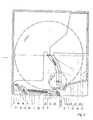
- Fig. 1 the device is cut vertically exactly in the middle. It shows the inner structure with the cover 1, the knife 2, the tension spring 3, the rear wall base 4, the slider 5 and the paper web 6 shown in broken lines, which is also drawn off the roll 7, also shown in broken lines.
- the hood 1 consists of the front wall, the ceiling and two side walls. It is open at the back and at the bottom.
- the rear wall 8 is not shown, on which two holding arms 9 are attached laterally.
- the holding arms 9 are covered by the side walls of the hood 1.
- the knife 2 is rotatably supported by pivot 10.
- the slider 5 is also supported by two laterally attached guide pins 11 in the holding arms 9 of the rear wall 8.
- the holding arms 9 have grooves 12 in which the pins 11 can slide.
- the grooves 12 have the shape of a wave.
- the knife 2 engages with the hook-shaped guide lugs 13 in eyelet-shaped openings 14 of the slide 5.
- the slide 5 rests with its rear end 15 on the rear wall base 4 and is held in this rest position by the tension spring 3.
- the tension spring 3 engages with one end on the pin 16 of the slide 5 and with its other end on the socket 17 of the bottom 4.
- the slide 5 remains in its rest position. After a sufficiently large section of the paper web has been pulled out, the train continues in an approximately horizontal direction. This change in the direction of pull on the paper web 6 causes the slide 5 to be moved in the direction of the front wall of the housing 1. The front edge 18 of the slide causes the knife 2 to rotate into the cutting position shown in FIG. 1. The cutting process begins with the penetration of the teeth of the knife 2 into the paper web 6. After the cutting process has ended, the spring 3 pulls the slide 5 back into its starting position. The end of the web located between the rounded curve 19 of the slider 5 and the knife edge falls down and hangs freely accessible from the housing 1 and the rear wall 8.
- Fig. 2 shows a section through the rear wall 8 and the hood 1.
- Slider 5 and knife 2 are in the rest position.
- the largest and smallest roller diameters are shown in dash-dot lines.
- the direction of rotation is indicated by the bright arrows.
- the downward movement of the guide pins 21 as the roller diameter becomes smaller is indicated by the full arrow.
- the rear wall 8 is mounted on a building wall.
- the openings 20 are used to introduce any fasteners.
- the roller 7 is inserted with its lateral guide pins 21 into the grooves 22 inserted in the side walls 9 of the rear wall 8.
- the grooves 22 run in a specific arc to the rear wall 8.
- the distance between the grooves 22 and the rear wall 8 is dimensioned such that the roller 7 does not rest with its surface on the rear wall 8.
- the roller 7 remains on the roller support table 23.
- the shape of the grooves 22 and the shape of the roller support table 23 and their mutual association with one another determine the tensile force at the end of the paper. Thrust faces 24 serve to guide the roller 7 laterally.
- the bore 32 is provided for receiving the pivot 10 of the knife 2.
- the groove 12 for receiving the pin 11 of the slide 5.
- the wave shape of the groove 12 is clearly visible.
- the bottom 4 extends between the two arms 9.
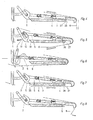
- FIG. 3 shows a knife section.
- the knife 2 pivots about the axis 10. Its cutting edge 25 is equipped with saw teeth 30.
- the knife 2 has on its surface the guide lugs 13 which, as described in FIG. 1, engage in corresponding openings 14 in the slide 5.
- 3 also shows the knife 2 in a side view.
- the slider 5 Due to the change in the direction of the web 6, the slider 5 is raised slightly in order to unlock it.
- the latching step 26 causes the slide 5 to be raised.
- Fig. 6 the knife 2 is in its cutting position and the web 6 is cut.
- the slider 5 is in its outermost position to the front.
- Fig. 7 the web 6 is cut.
- the slider 5 is retracted into its starting position by the spring 3. With the slider 5 also the knife 2.
- the knife 2 is already at its stop with its cutting edge.
- the latching step 26 of the slider 5 slides behind the edge 27 of the base 4 and causes the above-mentioned locking of the knife 2 in the protected position.
- the web 6 is also partially withdrawn.
Landscapes
- Health & Medical Sciences (AREA)
- Public Health (AREA)
- Replacement Of Web Rolls (AREA)
- Chutes (AREA)
- Machines For Laying And Maintaining Railways (AREA)
Abstract
Description
Die Erfindung betrifft eine Vorrichtung zur Ausgabe von Abschnitten eines auf einer Rolle aufgewickelten bahnförmigen Materials, insbesondere Papiers, mit Bereitstellung des dem abgetrennten Abschnitt nachfolgenden Bahnendes, mit einer Halterung für die Materialrolle und einem der Bahnbreite entsprechenden Messer, das um eine Achse verschwenkbar in Ruhestellung eingeschwenkt ist und für den Schneidvorgang ausgeschwenkt wird.The invention relates to a device for dispensing sections of a web-shaped material, in particular paper, wound on a roll, with provision of the web end following the separated section, with a holder for the roll of material and a knife corresponding to the web width, which is pivoted about an axis into the rest position and is swung out for the cutting process.
Eine bekannte Vorrichtung dieser Gattung ist in dem Gebrauchsmuster G 71 41 971.1 dargestellt. Die bekannte Vorrichtung besteht aus einem Gehäuse mit einer einsetzbaren Papierrolle, von der in beliebiger gewünschter Länge Papierabschnitte abtrennbar sind, z. B. Küchenpapiere. Das aus einem Schlitz heraushängende Bahnende wird mit den Händen ergriffen, in etwa senkrechter Richtung nach unten gezogen bis die gewünschte Länge vorliegt und dann durch Zug in etwa waagrechter Richtung durchtrennt. Für das Durchtrennen ist ein Messerbalken vorgesehen, der bei der horizontalen Zugbewegung bis zu einem Anschlag um seine Achse schwenkt und dann in vorbestimmter Lage verharrt. In dieser Lage erfolgt das Durchreißen der Papierbahn. Das Festhalten der Papierbahn wird während des Abreißvorganges dadurch unterstützt, daß das innenliegende Ende des Messerbalkens, die Papierbahn an einen Anschlag andrückt. Von Nachteil ist bei dieser Vorrichtung, daß das gewünschte Vorstehen des Bahnendes zum Ergreifen mit der Hand nicht immer gewährleistet ist. Sehr häufig springt die Papierbahn zurück und wird durch das Messer überdeckt. Auch ist das Zurückschwenken des Messerbalkens, welches durch das Eigengewicht desselben erfolgt, nicht immer zufriedenstellend. Geringfügige Verschmutzungen können die Drehbewegung des Messerbalkens negativ beeinflussen.A known device of this type is shown in the utility model G 71 41 971.1. The known device consists of a housing with an insertable paper roll, from which paper sections can be separated in any desired length, for. B. kitchen papers. The end of the web hanging out of a slit is gripped with the hands, pulled down in an approximately vertical direction until the desired length is obtained and then cut through in an approximately horizontal direction. For cutting, a knife bar is provided, which pivots about its axis during the horizontal pulling movement up to a stop and then remains in a predetermined position. In this position the paper web is torn. The holding of the paper web is supported during the tear-off process in that the inner end of the cutter bar presses the paper web against a stop. The disadvantage of this device is that the desired protrusion of the web end for gripping by hand is not always guaranteed. The paper web jumps back very often and is covered by the knife. Also, the pivoting back of the cutter bar, which is due to its own weight, is not always satisfactory. Slight contamination can negatively influence the rotary movement of the cutter bar.
Die Erfindung soll hier Abhilfe schaffen. Ihr liegt die Aufgabe zugrunde, eine Vorrichtung zur Ausgabe von Bahnabschnitten zu schaffen, bei der das Messer sicher in seine ungefährliche geschützte Lage einschwenkt, und bei der das nach dem Abrißvorgang aus der Vorrichtung hervorhängende Bahnende mit Bestimmtheit hervorhängt, und das in genügender Länge.The invention is intended to remedy this. It is the object of the invention to provide a device for dispensing web sections, in which the knife swings securely into its non-hazardous, protected position, and in which the web end protruding from the device after the tearing process protrudes with certainty, and of sufficient length.
Die Lösung der gestellten Aufgabe wird bei einer Vorrichtung der eingans genannten Gattung erfindungsgemäß dadurch erreicht, daß das Messer mit einem durch die Bahn betätigbaren und in Gegenrichtung unter Federkraft stehenden Schieber gekoppelt ist und durch den Schieber in seine ein- bzw. ausgeschwenkte Lage geschwenkt und in dieser festgehalten wird.The object is achieved in a device of the aforementioned type according to the invention in that the knife is coupled to an actuatable by the web and in the opposite direction under spring force slider and pivoted by the slider in its pivoted position and in and this is recorded.
Durch die Erfindung unterliegt das Messer nicht mehr rein vom Eigengewicht bestimmten Pendelbewegungen, sondern wird zwangsweise durch den Schieber geführt und während des ganzen Ein- bzw. Ausschwenkvorgangs durch den Schieber in einer vorbestimmten Stellung gehalten.Due to the invention, the knife is no longer subject to pendulum movements determined solely by its own weight, but is forcibly guided by the slide and held in a predetermined position during the entire pivoting-in and out process by the slide.
Der Schieber seinerseits ist über seitliche Zapfen in Nuten der Haltearme der Rückwand des Gehäuses geführt. Diese Führung kann so ausgebildet sein, daß in der eingeschwenkten Lage des Messers eine Arretierung des Messers gegeben ist. Diese Arretierung hat zur Folge, daß die auf das Messer in dieser Lage einwirkenden Kräfte das Messer nicht herausschwenken können. Dieses wird dadurch erreicht, daß den Nuten die Form einer nach oben gerichteten Welle erteilt wird.The slide, in turn, is guided in the grooves of the holding arms of the rear wall of the housing via lateral pins. This guide can be designed such that the knife is locked in the pivoted-in position of the knife. The result of this locking is that the forces acting on the knife in this position cannot pivot the knife out. This is achieved by giving the grooves the shape of an upward wave.
Die Verbindung zwischen dem Messer und dem Schieber kann über am Messer angebrachte hakenförmige Führungsansätze erfolgen, die in ösenförmige Öffnungen am Schieber eingreifen.The connection between the knife and the slide can be made by means of hook-shaped guide attachments attached to the knife, which engage in eye-shaped openings on the slide.
Mit seinem dem Zapfen abgewandten Ende gleitet der Schieber auf dem Boden des Gehäuses. Die den Schieber in seine Ausgangslage zurückziehende Federkraft wird durch eine am Schieber und am Rückwandboden angreifende Feder bewirkt. Der Schieber selbst kann einen rahmenförmigen Aufbau haben.With its end facing away from the pin, the slide slides on the bottom of the housing. The spring force pulling the slide back into its starting position is brought about by a spring acting on the slide and on the rear wall base. The slider itself can have a frame-shaped structure.
Um zu verhindern, daß bei unsachgemäßer Bedienung über den Schieber ein Ausschwenken des Messers erfolgt, kann der Schieber mit einer Raststufe versehen sein, die bei eingefahrenem Schieber und ausgeübter Zugkraft an der Bahn, am Rückwandboden einrastet und dadurch den Schieber in vorgegebener Lage hält, bis eine Änderung der Zugrichtung an der Bahn zur Horizontalen erfolgt. Um diesen Vorgang zu unterstützen, kann der Schieber mit einer Gleitrundung für die Bahn versehen sein, die eine nach unten weisende Nase hat. Diese Nase steht bei eingefahrenem Schieber vorzugsweise geringfügig über den Rückwandboden nach unten vor. Bei ausgefahrenem Schieber dagegen, bildet sie einen Anschlag an der Kante des Rückwandbodens.In order to prevent the knife from swinging out when improperly operated, the slider can be provided with a locking step that engages on the track and on the rear wall floor when the slider is retracted and the traction exerted, thereby holding the slider in a predetermined position until there is a change in the direction of the train on the track to the horizontal. To support this process, the slide can be provided with a sliding curve for the web, which has a nose pointing downwards. When the slider is retracted, this nose preferably protrudes slightly above the rear wall bottom. On the other hand, when the slide is extended, it forms a stop on the edge of the rear wall floor.
Die Bahnrolle ihrerseits ist mit seitlichen Führungszapfen versehen, die in schräg zur Rückwand verlaufenden in den Rückwandseitenwänden angebrachten Nuten geführt sind. Die Nuten sind so angeordnet, daß die Rolle mit ihrer Oberfläche auch bei kleiner werdendem Durchmesser immer auf dem Rollentragtisch der Rückwand aufliegt. Durch das Eigengewicht der Rolle, die Geometrie der Nuten sowie des Rollentragtisches wird die am Bahnende ausgeübte Zugkraft bestimmt. Um hier beste, an das abnehmende Gewicht der Rolle angepaßte Ergebnisse zu erreichen, können die Nuten die Form einer Kurvenschräge haben. Der Rollentragtisch ist mit schräg nach vorn verlaufenden Sockeln versehen, d.h. in seiner Lage und Form zu den Kurvenschrägen so ausgebildet, daß eine ausreichende Bremswirkung auf die Rolle auch bei kleiner werdendem Rollendurchmesser gewährleistet ist.For its part, the web roll is provided with lateral guide pins which are guided in grooves which run obliquely to the rear wall in the rear wall side walls. The grooves are arranged in such a way that the surface of the roller always rests on the rear wall of the roller support table even when the diameter becomes smaller. The tensile force exerted at the end of the web is determined by the weight of the roll, the geometry of the grooves and the roll support table. In order to achieve the best results here, adapted to the decreasing weight of the roller, the grooves can have the shape of a curved slope. The roll support table is provided with obliquely forward-extending bases, ie its position and shape with respect to the bevels are designed so that a sufficient braking effect on the roll is ensured even when the roll diameter becomes smaller.
Anhand eines Ausführungsbeispiels wird die Erfindung näher erläutert. Es zeigt:
- Fig. 1 in schematischer Schnitt-Darstellung den inneren Aufbau der Vorrichtung ohne Rückwand und seitliche Führungszapfen der Rolle,
- Fig. 2 einen Schnitt durch die Vorrichtung mit Abdeckhaube,
- Fig. 3 eine Vorder- und Seitenansicht des Messers,
- Fig. 4 bis Fig. 8 einen Schnitt durch den unteren Teil der Vorrichtung mit Schieber und Messer in schematischer Darstellung des Bewegungsablaufs.
- 1 is a schematic sectional view of the internal structure of the device without a rear wall and lateral guide pin of the roller,
- 2 shows a section through the device with cover,
- 3 is a front and side view of the knife,
- Fig. 4 to Fig. 8 shows a section through the lower part of the device with slide and knife in a schematic representation of the movement.
Vorrichtungen zur Ausgabe von Abschnitten von einer Papierrolle sind an sich bekannt. Aus diesem Grunde wird bei der nachfolgenden Darstellung lediglich auf die wesentlichen, mit der Erfindung im Zusammenhang stehenden Teile Bezug genommen.Devices for dispensing sections from a roll of paper are known per se. For this reason, the following illustration only refers to the essential parts related to the invention.
In Fig. 1 ist die Vorrichtung genau in der Mitte senkrecht geschnitten. Sie zeigt den inneren Aufbau mit der Abdeckhaube 1, dem Messer 2, der Zugfeder 3, dem Rückwandboden 4, dem Schieber 5 und der strichpunktiert eingezeichneten Papierbahn 6, die von der Rolle 7, ebenfalls strichpunktiert gezeichnet, abgezogen wird.In Fig. 1 the device is cut vertically exactly in the middle. It shows the inner structure with the
Die Haube 1 besteht aus der Vorderwand, der Decke und zwei Seitenwänden. Sie ist nach hinten und unten offen. Nicht dargestellt ist die Rückwand 8, an der seitlich zwei Haltearme 9 angebracht sind.The
Die Haltearme 9 sind von den Seitenwänden der Haube 1 abgedeckt. In den Haltearmen 9 der Rückwand 8 ist das Messer 2 über Drehzapfen 10 drehbar gelagert.The holding
Der Schieber 5 ist ebenfalls durch zwei seitlich angebrachte Führungszapfen 11 in den Haltearmen 9 der Rückwand 8 gelagert. Hierfür haben die Haltearme 9 Nuten 12, in denen die Zapfen 11 gleiten können. Die Nuten 12 haben die Form einer Welle. Das Messer 2 greift mit den hakenförmigen Führungsansätzen 13 in ösenförmige Öffnungen 14 des Schiebers 5 ein.The
Der Schieber 5 liegt mit seinem hinteren Ende 15 auf dem Rückwandboden 4 auf und wird in dieser Ruhelage durch die Zugfeder 3 gehalten. Die Zugfeder 3 greift mit einem Ende an dem Stift 16 des Schiebers 5 und mit ihrem anderen Ende an dem Stutzen 17 des Bodens 4 an.The
Wird die Papierbahn 6 in etwa senkrechter Richtung aus dem Gehäuse 1 und Rückwand 8 herausgezogen, so verbleibt der Schieber 5 in seiner Ruhestellung. Nachdem ein genügend großer Abschnitt der Papierbahn herausgezogen worden ist, wird der Zug in etwa waagerechter Richtung fortgesetzt. Diese Zugrichtungsänderung an der Papierbahn 6 bewirkt, daß der Schieber 5 in Richtung auf die Vorderwand des Gehäuses 1 bewegt wird. Die Vorderkante 18 des Schiebers bewirkt ein Drehen des Messers 2 in die in der Fig. 1 gezeigte Schneidposition. Mit dem Eindringen der Zähne des Messers 2 in die Papierbahn 6 beginnt der Schneidvorgang. Nachdem der Schneidvorgang beendet ist, zieht die Feder 3 den Schieber 5 in seine Ausgangsposition zurück. Das zwischen der Gleitrundung 19 des Schiebers 5 und der Messerschneide befindliche Bahnende, fällt nach unten und hängt frei zugänglich aus dem Gehäuse 1 und der Rückwand 8 heraus.If the
Die Fig. 2 zeigt einen Schnitt durch die Rückwand 8 und die Haube 1. Schieber 5 und Messer 2 sind in Ruhestellung. Der größte und kleinste Rollendurchmesser sind strichpunktiert eingezeichnet. Die Drehrichtung ist durch die hellen Pfeile angegeben. Das Abwärtswandern der Führungszapfen 21 bei kleiner werdendem Rollendurchmesser ist durch den vollen Pfeil angedeutet. Die Rückwand 8 wird an eine Gebäudewand montiert. Die Öffnungen 20 dienen zur Einführung etwaiger Befestigungsmittel.Fig. 2 shows a section through the
Die Rolle 7 wird mit ihren seitlichen Führungszapfen 21 in die in den Seitenwänden 9 der Rückwand 8 eingefügten Nuten 22 eingesetzt. Die Nuten 22 verlaufen in bestimmten Bogen zur Rückwand 8. Der Abstand der Nuten 22 zur Rückwand 8 ist so bemessen, daß die Rolle 7 mit ihrer Oberfläche an der Rückwand 8 nicht anliegt. Bei abnehmendem Durchmesser verbleibt die Rolle 7 auf dem Rollen-Tragtisch 23. Die Form der Nuten 22 und die Form des Rollen-Tragtisches 23 und ihre gegenseitige Zuordnung zueinander bestimmen die Zugkraft am Papierende. Anlaufflächen 24 dienen zur seitlichen Führung der Rolle 7.The
Im vorstehenden Arm 9 ist die Bohrung 32 zur Aufnahme des Drehzapfens 10 des Messers 2 vorgesehen. Darunter liegt die Nut 12, für die Aufnahme der Zapfen 11 des Schiebers 5. Die Wellenform der Nut 12 ist gut sichtbar. Der Boden 4 erstreckt sich zwischen den beiden Armen 9.In the
Die Fig. 3 zeigt einen Messerabschnitt. Das Messer 2 schwenkt um die Achse 10. Seine Schneidkante 25 ist mit Sägezähnen 30 ausgestattet. An mehreren Stellen hat das Messer 2 auf seiner Oberfläche die Führungsansätze 13, die wie bei der Fig. 1 beschrieben, in entsprechende Öffnungen 14 des Schiebers 5 eingreifen. Die Fig. 3 zeigt auch das Messer 2 in der Seitenansicht.3 shows a knife section. The
In den Fig. 4 bis 8 ist das Zusammenwirken zwischen Schieber 5 und Messer 2 dargestellt. In der Fig. 4 befindet sich der Schieber 5 in seiner Ausgangsposition. Durch die hellen Pfeile ist die Bewegungsrichtung der Papierbahn 6 angezeigt. Die Papierbahn 6 wird etwa senkrecht nach unten aus dem nicht mehr dargestellten Gehäuse herausgezogen. Durch die Zugkraft wird der Schieber 5 nach unten auf den Boden 4 gedrückt. Eine am Schieber 5 vorgesehene Raststufe 26, greift hinter die Kante 27, des Bodens 4. Dadurch wird der Schieber 5 fest in seiner Lage gehalten. Gleichzeitig hält das vordere Ende des Schiebers 5 das Messer 2 in verriegelter Position. Ein, aus welchen Gründen auch immer, ausgeübter Druck auf das Messer 2 kann das Messer nicht aus seiner vorgesehenen Verriegelungslage drücken.4 to 8, the interaction between
Sobald die Bahn 6, wie in Fig. 5 gezeigt, vom Benutzer aus gesehen, nach vorn gezogen wird. gleitet die Raststufe über die Kante 27 weg und der Schieber 5 wird, wie mit dem auf ihm befindlichen Pfeil angezeigt, in Richtung auf die Vorderwand des Gehäuses 1 bewegt. Dabei werden die Zapfen 11 in den Nuten 12, der Nut 12 folgend, zunächst schräg nach oben und dann wieder schräg nach unten, ebenfalls wieder auf die Vorderwand zu bewegt. Es erfolgt zunächst bei der Bewegung nach schräg oben eine Freigabe der Messerverriegelung und danach bei Überschreiten der Wellenkappe ein Verschwenken des Messers 2 um dessen Drehzapfen 10 in Richtung auf die Schneidposition.As soon as the
Durch die Zugrichtungsänderung an der Bahn 6 erfolgt ein leichtes Anheben des Schiebers 5,um ihn zu entriegeln. Das Anheben des Schiebers 5 wird durch die Raststufe 26 hervorgerufen.Due to the change in the direction of the
In Fig. 6 ist das Messer 2 in seiner Schneidposition und die Bahn 6 wird durchtrennt. Der Schieber 5 befindet sich in seiner äußersten Lage nach vorn.In Fig. 6 the
In Fig. 7 ist die Bahn 6 durchschnitten. Der Schieber 5 wird durch die Feder 3 in seine Ausgangsposition zurückgezogen. Mit dem Schieber 5 auch das Messer 2. Wenn die Führungszapfen 11 des Schiebers 5 den Wellenberg erreicht haben, befindet sich das Messer 2 bereits mit seiner Schneidkante am Anschlag. Bei weiterer Bewegung des Schiebers 5 gleitet die Raststufe 26 des Schiebers 5 hinter die Kante 27 des Bodens 4 und bewirkt die oben erwähnte Verriegelung des Messers 2 in der geschützten Lage. Mit der Zurückführung des Schiebers 5 wird auch die Bahn 6 teilweise zurückgezogen.In Fig. 7 the
Die Fig. 8 zeigt den letzten Schritt des Vorgangs, bei dem die Bahn 6 in ihre senkrechte Position einschwenkt. Das Messer 2 ist verriegelt, der Schieber 5 befindet sich in seiner Ausgangslage und das Bahnende der Bahn 6 bewegt sich in die senkrechte Bereitschaftsposition für den nachfolgenden Benutzungsvorgang.8 shows the last step of the process in which the
Claims (14)
dadurch gekennzeichnet,
daß das Messer (2) mit einem durch die Bahn (6) betätigbaren und in Gegenrichtung unter Federkraft (3) stehenden Schieber (5) gekoppelt ist und durch den Schieber (5) in seine ein- und ausgeschwenkte Lage geschwenkt und in dieser gehalten wird.1. Device for dispensing sections of a web-shaped material, in particular paper, wound on a roll, with provision of the web end following the severed section, with a holder for the roll of material and a knife corresponding to the web width, which can be pivoted about an axis in the inoperative position and is swung out for the cutting process,
characterized,
that the knife (2) is coupled to a slide (5) which can be actuated by the track (6) and is in the opposite direction under spring force (3) and is pivoted into and out of its position by the slide (5) and held in this position .
dadurch gekennzeichnet,
daß das Messer (2) über Drehzapfen (10) in Haltearmen (9) der Rückwand (8) gehalten ist.2. Device according to claim 1,
characterized,
that the knife (2) is held by pivot pins (10) in holding arms (9) of the rear wall (8).
dadurch gekennzeichnet,
daß der Schieber (5) über seitliche Führungszapfen (11) in Nuten (12) der Haltearme (9) der Rückwand (8) geführt ist.3. Device according to claim 1 or 2,
characterized,
that the slide (5) is guided via lateral guide pins (11) in grooves (12) of the holding arms (9) of the rear wall (8).
dadurch gekennzeichnet,
daß die Nuten (12) die Form einer nach oben gerichteten Welle haben.4. The device according to claim 3,
characterized,
that the grooves (12) have the shape of an upward wave.
dadurch gekennzeichnet,
daß das Messer (2) mit hakenförmigen Führungsansätzen (13) versehen ist, die in ösenförmige Öffnungen (14) am Schieber (5) eingreifen.5. Device according to one of claims 1 to 4,
characterized,
that the knife (2) is provided with hook-shaped guide lugs (13) which engage in eyelet-shaped openings (14) on the slide (5).
dadurch gekennzeichnet,
daß der Schieber (5) mit seinem den Zapfen (11) abgewandten Ende (15) auf dem Boden (4) gleitet.6. Device according to one of claims 1 to 5,
characterized,
that the slide (5) slides on the bottom (4) with its end (15) facing away from the pin (11).
dadurch gekennzeichnet,
daß die Federkraft durch eine am Schieber (5) und am Gehäuseboden (4) angreifende Feder (3) bewirkt wird.7. Device according to one of claims 1 to 6,
characterized,
that the spring force is brought about by a spring (3) acting on the slide (5) and on the housing base (4).
dadurch gekennzeichnet,
daß der Schieber (5) einen rahmenförmigen Aufbau hat.8. Device according to one of claims 1 to 7,
characterized,
that the slide (5) has a frame-shaped structure.
dadurch gekennzeichnet,
daß der Schieber (5) mit einer Raststufe (26) versehen ist, die bei eingefahrenem Schieber (5) und einer auf die Bahn (6) nach unten ausgeübten Zugkraft am Gehäuseboden (4) einrastet und bei Änderung der Zugkraft zur Horizontalen ausrastet.9. Device according to one of claims 1 to 8,
characterized,
that the slide (5) is provided with a latching step (26) which, when the slide (5) is retracted and a pulling force exerted on the web (6) downwards, engages on the housing base (4) and disengages from the horizontal when the pulling force changes.
dadurch gekennzeichnet,
daß der Schieber (5) eine Gleitrundung (19) für die Bahn (6) hat, die eine nach unten weisende Nase (28) aufweist.10. The device according to one of claims 1 to 9,
characterized,
that the slide (5) has a sliding curve (19) for the web (6), which has a downward-facing nose (28).
dadurch gekennzeichnet,
daß die Nase (28) bei eingefahrenem Schieber (5) über den Gehäuseboden (4) nach unten vorsteht.11. The device according to one of claims 1 to 10,
characterized,
that the nose (28) protrudes downward over the housing base (4) when the slide (5) is retracted.
dadurch gekennzeichnet,
daß die Rolle (7) seitliche Führungszapfen (21) hat, die in schräg zur Rückwand (8) verlaufenden, in Rückwandgehäuseseitenwänden (29) angebrachten Nuten (22) geführt sind.12. The device according to one of claims 1 to 11,
characterized,
that the roller (7) has lateral guide pins (21) which are guided in grooves (22) which run obliquely to the rear wall (8) and are arranged in rear wall housing side walls (29).
dadurch gekennzeichnet,
daß die Nuten (22) die Form einer Kurvenbogens haben.13. The device according to one of claims 1 to 12,
characterized,
that the grooves (22) have the shape of a curved curve.
dadurch gekennzeichnet,
daß die Rückwand (8) an ihrem unteren Ende (30) einen schräg nach vorn verlaufenden Rollen-Tragtisch (23) hat.14. The device according to one of claims 1 to 13,
characterized,
that the rear wall (8) has at its lower end (30) an obliquely forward roller support table (23).
Priority Applications (1)
| Application Number | Priority Date | Filing Date | Title |
|---|---|---|---|
| AT87117542T ATE50911T1 (en) | 1987-02-24 | 1987-11-27 | DEVICE FOR DISPENSING SECTION OF WEB-FORM MATERIAL WINDED ON A ROLL. |
Applications Claiming Priority (2)
| Application Number | Priority Date | Filing Date | Title |
|---|---|---|---|
| DE19873705808 DE3705808A1 (en) | 1987-02-24 | 1987-02-24 | DEVICE FOR DISPENSING SECTIONS OF A RAIL-SHAPED MATERIAL |
| DE3705808 | 1987-02-24 |
Publications (2)
| Publication Number | Publication Date |
|---|---|
| EP0279920A1 true EP0279920A1 (en) | 1988-08-31 |
| EP0279920B1 EP0279920B1 (en) | 1990-03-14 |
Family
ID=6321605
Family Applications (1)
| Application Number | Title | Priority Date | Filing Date |
|---|---|---|---|
| EP87117542A Expired - Lifetime EP0279920B1 (en) | 1987-02-24 | 1987-11-27 | Device for dispensing sheets of wound web material |
Country Status (3)
| Country | Link |
|---|---|
| EP (1) | EP0279920B1 (en) |
| AT (1) | ATE50911T1 (en) |
| DE (3) | DE3705808A1 (en) |
Cited By (4)
| Publication number | Priority date | Publication date | Assignee | Title |
|---|---|---|---|---|
| GB2255925A (en) * | 1991-02-06 | 1992-11-25 | Guardline Limited | Foil or film dispenser |
| EP0819640A2 (en) * | 1996-07-17 | 1998-01-21 | Heinrich J. Kesseböhmer Draht- und Metallwarenfabrik | Severing device for webs |
| WO1998051603A1 (en) * | 1997-05-14 | 1998-11-19 | Minnesota Mining And Manufacturing Company | Sheet material dispenser with safer sheet cutting means |
| CN111320022A (en) * | 2020-04-16 | 2020-06-23 | 南通远顺耐纤有限公司 | Flame-retardant ceramic fiber paper |
Families Citing this family (1)
| Publication number | Priority date | Publication date | Assignee | Title |
|---|---|---|---|---|
| DE4034504A1 (en) * | 1990-10-30 | 1992-05-07 | Feldmuehle Gmbh Scott | DEVICE FOR DISPENSING TRACK SECTIONS FROM A ROLLER |
Citations (3)
| Publication number | Priority date | Publication date | Assignee | Title |
|---|---|---|---|---|
| DE2007604A1 (en) * | 1969-02-27 | 1970-09-10 | Aschbacher, Paul, Bozen (Italien) | Dispenser for sheets of a certain size separated from a strip |
| CH576776A5 (en) * | 1974-04-26 | 1976-06-30 | Budmiger Hermann | Cotton wool dispenser - fitted with measuring and cutting devices refill pack and actuating member |
| DE2922581A1 (en) * | 1978-06-21 | 1980-01-24 | Apura Gmbh | DEVICE FOR DISPENSING PAPER SECTIONS OF PRESET LENGTH |
-
1987
- 1987-02-24 DE DE19873705808 patent/DE3705808A1/en not_active Withdrawn
- 1987-02-24 DE DE8717588U patent/DE8717588U1/en not_active Expired
- 1987-11-27 AT AT87117542T patent/ATE50911T1/en not_active IP Right Cessation
- 1987-11-27 DE DE8787117542T patent/DE3761872D1/en not_active Expired - Fee Related
- 1987-11-27 EP EP87117542A patent/EP0279920B1/en not_active Expired - Lifetime
Patent Citations (3)
| Publication number | Priority date | Publication date | Assignee | Title |
|---|---|---|---|---|
| DE2007604A1 (en) * | 1969-02-27 | 1970-09-10 | Aschbacher, Paul, Bozen (Italien) | Dispenser for sheets of a certain size separated from a strip |
| CH576776A5 (en) * | 1974-04-26 | 1976-06-30 | Budmiger Hermann | Cotton wool dispenser - fitted with measuring and cutting devices refill pack and actuating member |
| DE2922581A1 (en) * | 1978-06-21 | 1980-01-24 | Apura Gmbh | DEVICE FOR DISPENSING PAPER SECTIONS OF PRESET LENGTH |
Cited By (7)
| Publication number | Priority date | Publication date | Assignee | Title |
|---|---|---|---|---|
| GB2255925A (en) * | 1991-02-06 | 1992-11-25 | Guardline Limited | Foil or film dispenser |
| EP0819640A2 (en) * | 1996-07-17 | 1998-01-21 | Heinrich J. Kesseböhmer Draht- und Metallwarenfabrik | Severing device for webs |
| EP0819640A3 (en) * | 1996-07-17 | 1999-11-24 | Heinrich J. Kesseböhmer Draht- und Metallwarenfabrik | Severing device for webs |
| WO1998051603A1 (en) * | 1997-05-14 | 1998-11-19 | Minnesota Mining And Manufacturing Company | Sheet material dispenser with safer sheet cutting means |
| US6039102A (en) * | 1997-05-14 | 2000-03-21 | 3M Innovative Properties Company | Sheet material dispenser with safer sheet cutting means |
| US6418995B1 (en) | 1997-05-14 | 2002-07-16 | 3M Innovative Properties Company | Sheet material dispenser with safer sheet cutting means |
| CN111320022A (en) * | 2020-04-16 | 2020-06-23 | 南通远顺耐纤有限公司 | Flame-retardant ceramic fiber paper |
Also Published As
| Publication number | Publication date |
|---|---|
| ATE50911T1 (en) | 1990-03-15 |
| DE3705808A1 (en) | 1988-09-01 |
| DE3761872D1 (en) | 1990-04-19 |
| EP0279920B1 (en) | 1990-03-14 |
| DE8717588U1 (en) | 1989-03-30 |
Similar Documents
| Publication | Publication Date | Title |
|---|---|---|
| EP0729811B1 (en) | Card board box knife | |
| EP0941657A2 (en) | Leash device for a retractable leash for walking animals | |
| EP0483749A1 (en) | Dispenser for issuing sections of a strip of material from a supply roll | |
| DE1428855A1 (en) | Safety ski binding with a swivel plate with side jaws in the front | |
| EP0279920B1 (en) | Device for dispensing sheets of wound web material | |
| EP1026113A2 (en) | Foil dispenser | |
| DE3406880C2 (en) | Holders for paper rolls, especially toilet paper | |
| DE3527153C2 (en) | ||
| DE2639810C3 (en) | Method and device for pulling off a material web section of a predetermined length from a supply roll | |
| DE4339151C2 (en) | Tape unwinding device | |
| DE2934197C2 (en) | Storage aid for paper cutting devices | |
| DE69401663T2 (en) | PRUNING SHEARS WITH DECENTRATED LEVER | |
| DE3434651A1 (en) | DEVICE FOR UNLOCKING THE KEYSTONE AT THE FORK TREE OF A SURFBOARD | |
| DE2351699A1 (en) | Tear off device for paper web advancing mechanism - makes angled pull at paper and causes knife to swivel from rest to tear off position | |
| AT156566B (en) | Nail lifter. | |
| DE2727817A1 (en) | Safety catch for paper cutting guillotine - has pawl engaging notches in in blade holder released via lever clamping sheet stack | |
| DE2324911C3 (en) | cutting machine | |
| DE4020835C1 (en) | ||
| DE958450C (en) | Output device for individual sheets of paper or the like. | |
| DE2926622A1 (en) | DEVICE FOR CUTTING METAL WIRE IN LOWER LOWERS | |
| DE19541293A1 (en) | Circular saw protective gear with pivoted hood | |
| DE869327C (en) | Device for pulling out nails and similar connecting means, consisting of pliers with two legs | |
| AT409449B (en) | GUIDE ARRANGEMENT FOR A DOOR ELEMENT | |
| DE518604C (en) | Double-walled velvet cutting rod with exchangeable knife | |
| DE212019000339U1 (en) | Toilet roll holder |
Legal Events
| Date | Code | Title | Description |
|---|---|---|---|
| PUAI | Public reference made under article 153(3) epc to a published international application that has entered the european phase |
Free format text: ORIGINAL CODE: 0009012 |
|
| AK | Designated contracting states |
Kind code of ref document: A1 Designated state(s): AT BE CH DE FR LI NL |
|
| 17P | Request for examination filed |
Effective date: 19880811 |
|
| 17Q | First examination report despatched |
Effective date: 19890808 |
|
| GRAA | (expected) grant |
Free format text: ORIGINAL CODE: 0009210 |
|
| AK | Designated contracting states |
Kind code of ref document: B1 Designated state(s): AT BE CH DE FR LI NL |
|
| REF | Corresponds to: |
Ref document number: 50911 Country of ref document: AT Date of ref document: 19900315 Kind code of ref document: T |
|
| REF | Corresponds to: |
Ref document number: 3761872 Country of ref document: DE Date of ref document: 19900419 |
|
| ET | Fr: translation filed | ||
| PLBE | No opposition filed within time limit |
Free format text: ORIGINAL CODE: 0009261 |
|
| STAA | Information on the status of an ep patent application or granted ep patent |
Free format text: STATUS: NO OPPOSITION FILED WITHIN TIME LIMIT |
|
| 26N | No opposition filed | ||
| PGFP | Annual fee paid to national office [announced via postgrant information from national office to epo] |
Ref country code: DE Payment date: 20001018 Year of fee payment: 14 |
|
| PGFP | Annual fee paid to national office [announced via postgrant information from national office to epo] |
Ref country code: AT Payment date: 20001020 Year of fee payment: 14 |
|
| PGFP | Annual fee paid to national office [announced via postgrant information from national office to epo] |
Ref country code: FR Payment date: 20001027 Year of fee payment: 14 |
|
| PGFP | Annual fee paid to national office [announced via postgrant information from national office to epo] |
Ref country code: BE Payment date: 20001108 Year of fee payment: 14 |
|
| PGFP | Annual fee paid to national office [announced via postgrant information from national office to epo] |
Ref country code: CH Payment date: 20001109 Year of fee payment: 14 |
|
| PGFP | Annual fee paid to national office [announced via postgrant information from national office to epo] |
Ref country code: NL Payment date: 20001130 Year of fee payment: 14 |
|
| PG25 | Lapsed in a contracting state [announced via postgrant information from national office to epo] |
Ref country code: AT Free format text: LAPSE BECAUSE OF NON-PAYMENT OF DUE FEES Effective date: 20011127 |
|
| PG25 | Lapsed in a contracting state [announced via postgrant information from national office to epo] |
Ref country code: LI Free format text: LAPSE BECAUSE OF NON-PAYMENT OF DUE FEES Effective date: 20011130 Ref country code: CH Free format text: LAPSE BECAUSE OF NON-PAYMENT OF DUE FEES Effective date: 20011130 Ref country code: BE Free format text: LAPSE BECAUSE OF NON-PAYMENT OF DUE FEES Effective date: 20011130 |
|
| BERE | Be: lapsed |
Owner name: APURA G.M.B.H. Effective date: 20011130 |
|
| PG25 | Lapsed in a contracting state [announced via postgrant information from national office to epo] |
Ref country code: NL Free format text: LAPSE BECAUSE OF NON-PAYMENT OF DUE FEES Effective date: 20020601 |
|
| PG25 | Lapsed in a contracting state [announced via postgrant information from national office to epo] |
Ref country code: DE Free format text: LAPSE BECAUSE OF NON-PAYMENT OF DUE FEES Effective date: 20020702 |
|
| REG | Reference to a national code |
Ref country code: CH Ref legal event code: PL |
|
| PG25 | Lapsed in a contracting state [announced via postgrant information from national office to epo] |
Ref country code: FR Free format text: LAPSE BECAUSE OF NON-PAYMENT OF DUE FEES Effective date: 20020730 |
|
| NLV4 | Nl: lapsed or anulled due to non-payment of the annual fee |
Effective date: 20020601 |
|
| REG | Reference to a national code |
Ref country code: FR Ref legal event code: ST |
|
| REG | Reference to a national code |
Ref country code: FR Ref legal event code: ST |