EP0279004B1 - Procédé de fabrication d'une sonde de mesure - Google Patents
Procédé de fabrication d'une sonde de mesure Download PDFInfo
- Publication number
- EP0279004B1 EP0279004B1 EP87102263A EP87102263A EP0279004B1 EP 0279004 B1 EP0279004 B1 EP 0279004B1 EP 87102263 A EP87102263 A EP 87102263A EP 87102263 A EP87102263 A EP 87102263A EP 0279004 B1 EP0279004 B1 EP 0279004B1
- Authority
- EP
- European Patent Office
- Prior art keywords
- sensor
- glue
- sheath
- cover material
- probe
- Prior art date
- Legal status (The legal status is an assumption and is not a legal conclusion. Google has not performed a legal analysis and makes no representation as to the accuracy of the status listed.)
- Expired
Links
Images


Classifications
-
- G—PHYSICS
- G01—MEASURING; TESTING
- G01N—INVESTIGATING OR ANALYSING MATERIALS BY DETERMINING THEIR CHEMICAL OR PHYSICAL PROPERTIES
- G01N21/00—Investigating or analysing materials by the use of optical means, i.e. using sub-millimetre waves, infrared, visible or ultraviolet light
- G01N21/75—Systems in which material is subjected to a chemical reaction, the progress or the result of the reaction being investigated
- G01N21/77—Systems in which material is subjected to a chemical reaction, the progress or the result of the reaction being investigated by observing the effect on a chemical indicator
- G01N21/7703—Systems in which material is subjected to a chemical reaction, the progress or the result of the reaction being investigated by observing the effect on a chemical indicator using reagent-clad optical fibres or optical waveguides
-
- A—HUMAN NECESSITIES
- A61—MEDICAL OR VETERINARY SCIENCE; HYGIENE
- A61B—DIAGNOSIS; SURGERY; IDENTIFICATION
- A61B5/00—Measuring for diagnostic purposes; Identification of persons
- A61B5/145—Measuring characteristics of blood in vivo, e.g. gas concentration, pH value; Measuring characteristics of body fluids or tissues, e.g. interstitial fluid, cerebral tissue
- A61B5/14539—Measuring characteristics of blood in vivo, e.g. gas concentration, pH value; Measuring characteristics of body fluids or tissues, e.g. interstitial fluid, cerebral tissue for measuring pH
-
- A—HUMAN NECESSITIES
- A61—MEDICAL OR VETERINARY SCIENCE; HYGIENE
- A61B—DIAGNOSIS; SURGERY; IDENTIFICATION
- A61B5/00—Measuring for diagnostic purposes; Identification of persons
- A61B5/145—Measuring characteristics of blood in vivo, e.g. gas concentration, pH value; Measuring characteristics of body fluids or tissues, e.g. interstitial fluid, cerebral tissue
- A61B5/1455—Measuring characteristics of blood in vivo, e.g. gas concentration, pH value; Measuring characteristics of body fluids or tissues, e.g. interstitial fluid, cerebral tissue using optical sensors, e.g. spectral photometrical oximeters
- A61B5/1459—Measuring characteristics of blood in vivo, e.g. gas concentration, pH value; Measuring characteristics of body fluids or tissues, e.g. interstitial fluid, cerebral tissue using optical sensors, e.g. spectral photometrical oximeters invasive, e.g. introduced into the body by a catheter
Definitions
- This invention relates to a method for manufac- ' turing a measuring probe, especially an optical probe for the invasive measurement of blood parameters such as pH, p0 2 or pC02, with at least one sensor having a selective membrane and a sheath at least partially covering said sensor and fastened on said sensor by a glue.
- Probes for the invasive measurement of blood parameters consist of at least one sensor comprising an optical fiber, said fiber ending up with a gel zone containing a dye.
- the optical density or another optical parameter of that dye varies with the blood parameter (such as pH) to be measured.
- a reflector is positioned on the other side of the dye-containing gel.
- the end of the fiber, the gel and the reflector are surrounded by a semi-permeable envelope (for example, a hydrogen ion permeable envelope in the case of a pH sensor) to keep the gel in place.
- Light from this optical fiber passes the dye-containing gel, is reflected by said reflector, passes the gel again and is transmitted through the optical fiber to an appropriate detector which measures light attenuation or changes in other optical parameters caused by the dye.
- This attenuation or change is a function of the blood parameter to be measured, and the relation between attenuation, absorbance or change of another optical parameter and the blood parameter is well-known.
- Such a probe can be introduced into a patient's artery to measure - depending on the dye - various blood parameters such as pH, p0 2 or pC0 2 .
- the sensor(s) and/or the stabilizing core have to be coupled mechanically. This can be achieved by use of a sheath covering the front end of the probe and being appropriately perforated to allow the ions (in the case of a pH sensor) or the gas molecules (in the case of a P 0 2 or a pC0 2 sensor) to reach the permeable envelope of the sensor, pass it and diffuse into the dye-containing gel.
- the sheath has to be secured by a glue or adhesive.
- the sheath - which does not cover the diffusion zones, i.e. the selective membranes over the dye-containing gel - is loosely placed over the ends of some sensors each of them intended to measure a specific blood parameter.
- the cover material is applied onto the selective membranes (the region of the diffusion zones) and hardened.
- said cover material is air-hardenable.
- the glue is introduced between the sensors and the sheath through appropriate openings. These openings can be, for example, the front end of the sheath or special bores.
- the glue - for example, a two-component glue or an epoxy - then creeps along the sensor and the inside of the sheath and attaches the sensors to that sheath.
- the selective membranes are not covered by the glue as these selective membranes are just covered by the cover material which is resistant to the glue.
- the cover material is dissolved in said dissolvent, preferably a fluid, which neither attacks the glue nor the probe components.
- this dissolvent is water, but other fluids such as alcohol also do not attack the glue or the probe components.
- a well-suited cover material for this purpose is silicate, for example a silicate consisting of NazSiOs and Na 2 Si0 5 or a silicate consisting of K 2 Si0 3 and K 2 SiOs.
- Other materials meeting the requirements are organic substances such as gelatine or pectine or a melt of polyethylenglycol (PEG). Such Polyethylenglycol is melted at a temperature range of 40 to 50 ° C, applied to the selective membranes and hardened at room temperature.
- PEG polyethylenglycol
- the described method is not restricted to a probe containing a plurality of optical sensors.
- the probe can also consist of one or more than one sensor and a stabilizing core, for example, a wire or the like. This wire is used to stabilize the sensor(s) in the region of the diffusion zones.
- a diffusion zone consists of a dye-containing gel (covered by a membrane) and is mechanically not very stable.
- the new method can also be used to manufacture other probes than optical ones.
- the sensor comprises an ion sensitive field effect transistor (ISFET) being covered by a selective membrane.
- ISFET ion sensitive field effect transistor
- the new method is also applicable if the sequence of process steps is in another order than explained above.
- a major advantage of the method according to the present invention is that a probe can be manufactured with a sheath covering the sensors partially, stabilizing them and fastened on them by a glue without the glue covering the selective membranes of the sensors and therefore not influencing the characteristics of the probe. Another advantage is that this method can be performed very easily, especially in a minimum of time and with a minimum of additional tools. A further advantage is that the glue does not have to be dosed exactly. Furthermore, the required materials are very cheap and easy to handle.
- the new method is also applicable if the probe consists only of a single sensor (even without stabilizing core) and a sheath fastened on said sensor by a glue.
- Figure 1 shows a system for the invasive measurement of blood parameters, for example of the pH value.
- the light of an optical transmitter 1 is directed into an optical fiber 2 (see arrow 2a).
- a plastic fiber is used which has the advantage that it cannot break off inside the body of a patient and that it can be sterilized by gamma rays. Usually a train of light pulses is used, but this is not a strict requirement.
- the light passes an optical coupler 3 and reaches tip 4 of the sensor said tip being intended to be introduced into the artery of a patient.
- Tip 4 of the sensor contains a gel into which a dye such as phenol red is immobilized.
- Said dye modifies at least one optical parameter, preferably the intensity, of the light depending on the pH (or, in other cases, p0 2 or pC0 2 ) value of the blood.
- the modified light is reflected into the same fiber and, passing through optical coupler 3, reaches an optical receiver 5 (see arrow 5a).
- FIG 2 shows the details of tip 4 of an optical sensor using a system according to Figure 1.
- Light directed in optical fiber 6 reaches a dye-containing gel 7, the absorption spectrum of said dye - for example, phenol red - being dependent on the pH value of the blood.
- the light is then reflected at reflector 8.
- this reflector is made of metal such as platinum, the surface of this metal being polished on the side of gel 7.
- the whole system is packed in a selective membrane or envelope 9, this membrane being permeable to the ions or gas molecules to be measured - in case of a pH electrode for hydrogen ions - so that these ions/gas molecules can reach the dye-containing gel.
- Membrane 9 is fastened on the optical fiber 6 and the reflector 8 by a glue 10.
- the preferred material for membrane 9 is a hydrophilic material such as cellulose.
- FIG 3 is a perspective view of the end of an optical probe containing two optical sensors to measure various blood parameters such as, for example, pH, p0 2 or pC0 2 .
- Each sensor consists of the fiber, a dye-containing gel, a reflector and permeable or selective membrane as generally referred to as numeral 11 and consists of the optical fiber 12, diffusion zone 13 (the dye-containing gel is not shown in this example) and reflector 14. The whole sensor is surrounded by a selective membrane 15.
- the p0 2 sensor is generally referred to as numeral 17. Instead of a p0 2 sensor, a pC0 2 sensor can also be used.
- the probe is also equipped with a stabilizing core, in this case a wire 16, which guarantees the mechanical stability of the probe especially in the region of the diffusion zones.
- the two sensors - pH sensor 11 and p0 2 sensor 17 - are surrounded by a sheath 18, for example, a polyimide sheath, fastened on sensors 11 and 17 and on wire 16 by a glue, for example, a two-component glue.
- Said sheath must have at least one opening so that the patient's blood can be in contact with the diffusion zones.
- sheath 18 consists of two parts 18a and 18b which do not cover the diffusion zones of the single sensors.
- the whole probe (reference numeral 19) is preferably intended to be introduced into the artery of a patient for the purpose of measuring blood parameters. Therefore, this probe has to have a very small outer diameter.
- the probe of Figure 3 has an outer diameter of 0.4 to 0.7 mm (the single sensors having a diameter of about 0.12 mm). Of course, it is also possible to introduce the probe into the vein of a patient.
- the optical fibers are preferably polymethylmethacrylate (PMMA) light guides.
- FIG. 3 Another probe with the principal mechanical design of Figure 3 consists of two optical fibers, one of them conducting light from the transmitter to the diffusion zone and another conducting the reflected light back to the receiver (differing from the arrangement shown in Figure 1).
- Figure 4 is a longitudinal section of a probe as shown in Figure 3. According to this section, the outer end of the probe is on the right-hand side and not on the left-hand side as in Figure 3.
- Figure 4 shows the effect the fastening parts 18a and 18b of sheath 18 on the sensors by a glue.
- the glue 22 creeps along the sensors and thereby covers the diffusion zones, i.e. the selective membranes, which either makes the probe unusable or increases its time constant to unacceptable values.
- This effect is independent of the order of manufacturing steps, e.g. whether the sheath is first placed over the sensor and then the glue is applied through appropriate openings or whether the glue is first applied to the sensors and then the sheath is put over the same.
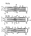
- Figures 5a to 5c show - in a similar longitudinal section as Figure 4 - the method according to the invention which ensures that, after the manufacturing process, the selective membranes are free from glue so that the time constants are as short as possible.
- the reference numerals used are the same as in Figures 3 and 4 (although these figures do not shown the new method).
- the two parts 18a and 18b of sheath 18 are placed over the optical sensors. Then, a silicate solution 21 is spread on the diffusion zones and totally covers them.
- the glue is introduced through openings of sheath 18 as shown in Figure 15b. As the silicate has just hardened, the glue 22 cannot cover the diffusion zones of the sensors.
- the glue may, for example, be introduced through the front hole of part 18b (reference numeral 23) and/or through an opening of part 18a on the monitor side (not shown in Figure 5b).
- the glue may creep along the inner side of the sensors (shown by arrow 24). This is possible if the silicate covers only the outer surfaces of the sensors, e.g. the region of arrow 24 is free of silicate. In contrast, it is also possible to cover the sensor diffusion zones totally with silicate in which case the glue cannot creep along their inner surfaces.
- Figure 6 shows a probe with another sheath before dissolution of the silicate.
- Two sensors 25 and 26 are surrounded by selective membranes 27 and 28, each of them covering the dye-containing gels 29 and 30 as well as reflectors 31 and 32.
- these sensors are surrounded by a cable sheath 33.
- the front end sheath 34 is made of metal, in particular stainless steel, and has two openings 35a and 35b to allow the blood to reach the selective membranes of the sensors. Additionally, it guarantees good mechanical stability also in the region of the diffusion zones.
- the glue 36 has just hardened, but the silicate 37 is not yet dissolved in water.
- the silicate protects the selective membranes so that they cannot be covered by the glue.
- Figure 7 is a perspective view of the probe of Figure 6 and offers an improved impression of sheath 34 and its openings 35a and 35b. Neither the glue nor the silicate are shown in this Figure.
Landscapes
- Health & Medical Sciences (AREA)
- Physics & Mathematics (AREA)
- Life Sciences & Earth Sciences (AREA)
- Pathology (AREA)
- Engineering & Computer Science (AREA)
- General Health & Medical Sciences (AREA)
- Biophysics (AREA)
- Surgery (AREA)
- Veterinary Medicine (AREA)
- Public Health (AREA)
- Animal Behavior & Ethology (AREA)
- Molecular Biology (AREA)
- Chemical & Material Sciences (AREA)
- Optics & Photonics (AREA)
- Medical Informatics (AREA)
- Biomedical Technology (AREA)
- Heart & Thoracic Surgery (AREA)
- Plasma & Fusion (AREA)
- Immunology (AREA)
- Analytical Chemistry (AREA)
- General Physics & Mathematics (AREA)
- Chemical Kinetics & Catalysis (AREA)
- Biochemistry (AREA)
- Spectroscopy & Molecular Physics (AREA)
- Measurement Of The Respiration, Hearing Ability, Form, And Blood Characteristics Of Living Organisms (AREA)
Claims (9)
Priority Applications (5)
| Application Number | Priority Date | Filing Date | Title |
|---|---|---|---|
| EP87102263A EP0279004B1 (fr) | 1987-02-17 | 1987-02-17 | Procédé de fabrication d'une sonde de mesure |
| DE8787102263T DE3760300D1 (en) | 1987-02-17 | 1987-02-17 | Method for manufacturing a measuring probe |
| JP63036426A JPS63212332A (ja) | 1987-02-17 | 1988-02-17 | 測定用プローブの製造方法 |
| US07/157,204 US4900381A (en) | 1987-02-17 | 1988-02-17 | Method for manufacturing a measuring probe |
| SG767/90A SG76790G (en) | 1987-02-17 | 1990-09-18 | Method for manufacturing a measuring probe |
Applications Claiming Priority (1)
| Application Number | Priority Date | Filing Date | Title |
|---|---|---|---|
| EP87102263A EP0279004B1 (fr) | 1987-02-17 | 1987-02-17 | Procédé de fabrication d'une sonde de mesure |
Publications (2)
| Publication Number | Publication Date |
|---|---|
| EP0279004A1 EP0279004A1 (fr) | 1988-08-24 |
| EP0279004B1 true EP0279004B1 (fr) | 1989-07-12 |
Family
ID=8196768
Family Applications (1)
| Application Number | Title | Priority Date | Filing Date |
|---|---|---|---|
| EP87102263A Expired EP0279004B1 (fr) | 1987-02-17 | 1987-02-17 | Procédé de fabrication d'une sonde de mesure |
Country Status (5)
| Country | Link |
|---|---|
| US (1) | US4900381A (fr) |
| EP (1) | EP0279004B1 (fr) |
| JP (1) | JPS63212332A (fr) |
| DE (1) | DE3760300D1 (fr) |
| SG (1) | SG76790G (fr) |
Cited By (1)
| Publication number | Priority date | Publication date | Assignee | Title |
|---|---|---|---|---|
| US6731976B2 (en) | 1997-09-03 | 2004-05-04 | Medtronic, Inc. | Device and method to measure and communicate body parameters |
Families Citing this family (17)
| Publication number | Priority date | Publication date | Assignee | Title |
|---|---|---|---|---|
| EP0336985B1 (fr) * | 1988-04-09 | 1993-01-27 | Hewlett-Packard GmbH | Méthode de fabrication d'une sonde optique |
| US5047627A (en) * | 1990-05-18 | 1991-09-10 | Abbott Laboratories | Configuration fiber-optic blood gas sensor bundle and method of making |
| DE69023496T2 (de) * | 1990-08-13 | 1996-03-21 | Hewlett Packard Gmbh | Optische Sonde. |
| EP0476161A1 (fr) * | 1990-09-17 | 1992-03-25 | Hewlett-Packard GmbH | Sonde optique |
| US5176882A (en) * | 1990-12-06 | 1993-01-05 | Hewlett-Packard Company | Dual fiberoptic cell for multiple serum measurements |
| US5335305A (en) * | 1991-12-19 | 1994-08-02 | Optex Biomedical, Inc. | Optical sensor for fluid parameters |
| FR2689977B1 (fr) * | 1992-04-14 | 1997-01-24 | Inst Francais Du Petrole | Cellule de mesure a membrane a permeabilite selective et son procede de fabrication. |
| CA2096582A1 (fr) * | 1992-05-22 | 1993-11-23 | Erich H. Wolf | Sonde renforcee pour catheter |
| US6144866A (en) * | 1998-10-30 | 2000-11-07 | Medtronic, Inc. | Multiple sensor assembly for medical electric lead |
| US7249949B2 (en) * | 2004-06-29 | 2007-07-31 | Lifecore Biomedical, Inc. | Internal connection dental implant |
| ES2307352B1 (es) * | 2005-04-12 | 2009-09-18 | Bti, I+D, S.L. | Implante dental y piezas destinadas a ser conectadas a un implante dental, y la conexion interna entre el implante dental y cada pieza. |
| GB2437057A (en) * | 2006-04-12 | 2007-10-17 | Sean Julian Thomas | Tube having positioning means for delivering fluid to a predetermining location |
| ATE507773T1 (de) * | 2007-01-23 | 2011-05-15 | Neuronano Ab | Elektrodenreihe |
| US8306632B2 (en) * | 2007-01-23 | 2012-11-06 | Neuronano Ab | Dissociating multi-channel electrode |
| US9675288B2 (en) | 2013-01-29 | 2017-06-13 | Hewlett-Packard Development Company, L.P. | Apparatus having surface-enhanced spectroscopy elements on an exterior surface |
| ES2934139T3 (es) * | 2015-01-05 | 2023-02-17 | Nipro Corp | Medidor de flujo sanguíneo y dispositivo de medición |
| JP6300864B2 (ja) * | 2016-08-09 | 2018-03-28 | ヒューレット−パッカード デベロップメント カンパニー エル.ピー.Hewlett‐Packard Development Company, L.P. | 外面に表面増感分光法要素を有する装置 |
Family Cites Families (5)
| Publication number | Priority date | Publication date | Assignee | Title |
|---|---|---|---|---|
| US3304353A (en) * | 1963-03-25 | 1967-02-14 | Pharmaseal Lab | Method of catheter manufacture |
| US3544668A (en) * | 1968-07-22 | 1970-12-01 | Davol Inc | Method of manufacturing a balloon catheter |
| US3926705A (en) * | 1974-07-25 | 1975-12-16 | Western Acadia | Silicone catheter and process for manufacturing same |
| EP0073558A3 (fr) * | 1981-08-25 | 1984-09-26 | THE UNITED STATES OF AMERICA as represented by the Secretary United States Department of Commerce | Capteur à fibres optiques pour la mesure de pH de tissus |
| US4557900A (en) * | 1982-09-28 | 1985-12-10 | Cardiovascular Devices, Inc. | Optical sensor with beads |
-
1987
- 1987-02-17 DE DE8787102263T patent/DE3760300D1/de not_active Expired
- 1987-02-17 EP EP87102263A patent/EP0279004B1/fr not_active Expired
-
1988
- 1988-02-17 JP JP63036426A patent/JPS63212332A/ja active Pending
- 1988-02-17 US US07/157,204 patent/US4900381A/en not_active Expired - Lifetime
-
1990
- 1990-09-18 SG SG767/90A patent/SG76790G/en unknown
Cited By (1)
| Publication number | Priority date | Publication date | Assignee | Title |
|---|---|---|---|---|
| US6731976B2 (en) | 1997-09-03 | 2004-05-04 | Medtronic, Inc. | Device and method to measure and communicate body parameters |
Also Published As
| Publication number | Publication date |
|---|---|
| SG76790G (en) | 1990-11-23 |
| US4900381A (en) | 1990-02-13 |
| JPS63212332A (ja) | 1988-09-05 |
| DE3760300D1 (en) | 1989-08-17 |
| EP0279004A1 (fr) | 1988-08-24 |
Similar Documents
| Publication | Publication Date | Title |
|---|---|---|
| EP0279004B1 (fr) | Procédé de fabrication d'une sonde de mesure | |
| CA1292665C (fr) | Sonde a fibre optique pour la quantification de reactions colorimetriques | |
| US5005576A (en) | Optical probe | |
| US5326531A (en) | CO2 sensor using a hydrophilic polyurethane matrix and process for manufacturing | |
| US5166990A (en) | Multiple optical fiber event sensor and method of manufacture | |
| US4710623A (en) | Optical fiber catheter with fiber-contained reactive element | |
| CA1334372C (fr) | Sonde de mesure de parametres sanguins | |
| US4785814A (en) | Optical probe for measuring pH and oxygen in blood and employing a composite membrane | |
| US5119463A (en) | Compound optical probe employing single optical waveguide | |
| US4200110A (en) | Fiber optic pH probe | |
| US5335305A (en) | Optical sensor for fluid parameters | |
| US5006314A (en) | Sensor and method for sensing the concentration of a component in a medium | |
| EP0471519A1 (fr) | Sonde d'événement à fibres optiques multiples et méthode de fabrication | |
| US4854321A (en) | Integrated optic system for monitoring blood gases | |
| JPH02259453A (ja) | 光導波路センサ及び該センサの製造方法 | |
| WO2002019898A2 (fr) | Sondes a fibres optiques multiparametres | |
| US5120510A (en) | Sensor and method for sensing the concentration of a component in a medium | |
| KR20080019204A (ko) | 생체조직의 산소 함량을 측정하기 위한 탐침 및 이러한탐침을 구비한 카테터 | |
| EP0471861B1 (fr) | Sonde optique | |
| JP2628355B2 (ja) | 生理学的測定装置のための光ファイバープローブコネクター | |
| WO1992019150A1 (fr) | Sonde d'insertion directe dans les tissus d'un patient | |
| US5271073A (en) | Optical fiber sensor and method of manufacture | |
| JP6153937B2 (ja) | 哺乳類の間質液中の物質の濃度を決定するための光学センサ用測定チャンバ | |
| JPH04233456A (ja) | 分析物濃度の測定方法及び装置 | |
| EP0215854A4 (fr) | Senseur chimique a fibre optique. |
Legal Events
| Date | Code | Title | Description |
|---|---|---|---|
| PUAI | Public reference made under article 153(3) epc to a published international application that has entered the european phase |
Free format text: ORIGINAL CODE: 0009012 |
|
| 17P | Request for examination filed |
Effective date: 19880502 |
|
| AK | Designated contracting states |
Kind code of ref document: A1 Designated state(s): DE FR GB |
|
| 17Q | First examination report despatched |
Effective date: 19881109 |
|
| GRAA | (expected) grant |
Free format text: ORIGINAL CODE: 0009210 |
|
| AK | Designated contracting states |
Kind code of ref document: B1 Designated state(s): DE FR GB |
|
| REF | Corresponds to: |
Ref document number: 3760300 Country of ref document: DE Date of ref document: 19890817 |
|
| ET | Fr: translation filed | ||
| R20 | Corrections of a patent specification |
Effective date: 19891012 |
|
| PLBE | No opposition filed within time limit |
Free format text: ORIGINAL CODE: 0009261 |
|
| STAA | Information on the status of an ep patent application or granted ep patent |
Free format text: STATUS: NO OPPOSITION FILED WITHIN TIME LIMIT |
|
| 26N | No opposition filed | ||
| PGFP | Annual fee paid to national office [announced via postgrant information from national office to epo] |
Ref country code: DE Payment date: 19940201 Year of fee payment: 8 |
|
| PGFP | Annual fee paid to national office [announced via postgrant information from national office to epo] |
Ref country code: GB Payment date: 19940208 Year of fee payment: 8 |
|
| PGFP | Annual fee paid to national office [announced via postgrant information from national office to epo] |
Ref country code: FR Payment date: 19940224 Year of fee payment: 8 |
|
| PG25 | Lapsed in a contracting state [announced via postgrant information from national office to epo] |
Ref country code: GB Effective date: 19950217 |
|
| GBPC | Gb: european patent ceased through non-payment of renewal fee |
Effective date: 19950217 |
|
| PG25 | Lapsed in a contracting state [announced via postgrant information from national office to epo] |
Ref country code: FR Effective date: 19951031 |
|
| PG25 | Lapsed in a contracting state [announced via postgrant information from national office to epo] |
Ref country code: DE Effective date: 19951101 |
|
| REG | Reference to a national code |
Ref country code: FR Ref legal event code: ST |