EP0278630A2 - Kälteanlage mit kontinuierlich regelbarer Leistung - Google Patents
Kälteanlage mit kontinuierlich regelbarer Leistung Download PDFInfo
- Publication number
- EP0278630A2 EP0278630A2 EP88300659A EP88300659A EP0278630A2 EP 0278630 A2 EP0278630 A2 EP 0278630A2 EP 88300659 A EP88300659 A EP 88300659A EP 88300659 A EP88300659 A EP 88300659A EP 0278630 A2 EP0278630 A2 EP 0278630A2
- Authority
- EP
- European Patent Office
- Prior art keywords
- compressor
- motor
- speed
- temperature
- refrigeration system
- Prior art date
- Legal status (The legal status is an assumption and is not a legal conclusion. Google has not performed a legal analysis and makes no representation as to the accuracy of the status listed.)
- Withdrawn
Links
- 238000005057 refrigeration Methods 0.000 title claims abstract description 48
- 239000003507 refrigerant Substances 0.000 claims abstract description 14
- 230000008878 coupling Effects 0.000 claims description 44
- 238000010168 coupling process Methods 0.000 claims description 44
- 238000005859 coupling reaction Methods 0.000 claims description 44
- 238000000034 method Methods 0.000 claims description 16
- 230000008859 change Effects 0.000 claims description 6
- 230000008093 supporting effect Effects 0.000 claims description 6
- 238000001704 evaporation Methods 0.000 claims description 5
- 230000035939 shock Effects 0.000 claims description 3
- 230000003247 decreasing effect Effects 0.000 claims description 2
- 238000011217 control strategy Methods 0.000 abstract description 4
- 230000009183 running Effects 0.000 description 8
- 230000000875 corresponding effect Effects 0.000 description 7
- 230000008569 process Effects 0.000 description 7
- 230000008901 benefit Effects 0.000 description 5
- 239000003921 oil Substances 0.000 description 5
- 238000009529 body temperature measurement Methods 0.000 description 4
- 230000001351 cycling effect Effects 0.000 description 4
- 230000007246 mechanism Effects 0.000 description 4
- 239000000523 sample Substances 0.000 description 4
- 238000012360 testing method Methods 0.000 description 4
- 208000036366 Sensation of pressure Diseases 0.000 description 3
- 230000000694 effects Effects 0.000 description 3
- 230000006870 function Effects 0.000 description 3
- 238000005259 measurement Methods 0.000 description 3
- 238000007514 turning Methods 0.000 description 3
- 229910052782 aluminium Inorganic materials 0.000 description 2
- XAGFODPZIPBFFR-UHFFFAOYSA-N aluminium Chemical compound [Al] XAGFODPZIPBFFR-UHFFFAOYSA-N 0.000 description 2
- 238000004891 communication Methods 0.000 description 2
- 230000006854 communication Effects 0.000 description 2
- 238000013461 design Methods 0.000 description 2
- 238000010586 diagram Methods 0.000 description 2
- 238000009434 installation Methods 0.000 description 2
- 229910052751 metal Inorganic materials 0.000 description 2
- 239000002184 metal Substances 0.000 description 2
- 230000001052 transient effect Effects 0.000 description 2
- 244000258271 Galium odoratum Species 0.000 description 1
- 235000008526 Galium odoratum Nutrition 0.000 description 1
- CYTYCFOTNPOANT-UHFFFAOYSA-N Perchloroethylene Chemical compound ClC(Cl)=C(Cl)Cl CYTYCFOTNPOANT-UHFFFAOYSA-N 0.000 description 1
- 230000003213 activating effect Effects 0.000 description 1
- -1 chloroprene compound Chemical class 0.000 description 1
- 239000010725 compressor oil Substances 0.000 description 1
- 238000004590 computer program Methods 0.000 description 1
- 238000011109 contamination Methods 0.000 description 1
- 238000001816 cooling Methods 0.000 description 1
- 125000004122 cyclic group Chemical group 0.000 description 1
- 238000002405 diagnostic procedure Methods 0.000 description 1
- 235000013305 food Nutrition 0.000 description 1
- 239000012208 gear oil Substances 0.000 description 1
- 238000005461 lubrication Methods 0.000 description 1
- 238000012423 maintenance Methods 0.000 description 1
- 239000010705 motor oil Substances 0.000 description 1
- 238000013021 overheating Methods 0.000 description 1
- 238000012545 processing Methods 0.000 description 1
- 238000005086 pumping Methods 0.000 description 1
- 230000009467 reduction Effects 0.000 description 1
- 238000012552 review Methods 0.000 description 1
- 230000011664 signaling Effects 0.000 description 1
- 238000009491 slugging Methods 0.000 description 1
- 230000003068 static effect Effects 0.000 description 1
- 238000010257 thawing Methods 0.000 description 1
Images


Classifications
-
- F—MECHANICAL ENGINEERING; LIGHTING; HEATING; WEAPONS; BLASTING
- F25—REFRIGERATION OR COOLING; COMBINED HEATING AND REFRIGERATION SYSTEMS; HEAT PUMP SYSTEMS; MANUFACTURE OR STORAGE OF ICE; LIQUEFACTION SOLIDIFICATION OF GASES
- F25B—REFRIGERATION MACHINES, PLANTS OR SYSTEMS; COMBINED HEATING AND REFRIGERATION SYSTEMS; HEAT PUMP SYSTEMS
- F25B49/00—Arrangement or mounting of control or safety devices
- F25B49/02—Arrangement or mounting of control or safety devices for compression type machines, plants or systems
- F25B49/025—Motor control arrangements
-
- F—MECHANICAL ENGINEERING; LIGHTING; HEATING; WEAPONS; BLASTING
- F04—POSITIVE - DISPLACEMENT MACHINES FOR LIQUIDS; PUMPS FOR LIQUIDS OR ELASTIC FLUIDS
- F04B—POSITIVE-DISPLACEMENT MACHINES FOR LIQUIDS; PUMPS
- F04B49/00—Control, e.g. of pump delivery, or pump pressure of, or safety measures for, machines, pumps, or pumping installations, not otherwise provided for, or of interest apart from, groups F04B1/00 - F04B47/00
- F04B49/06—Control using electricity
- F04B49/065—Control using electricity and making use of computers
-
- F—MECHANICAL ENGINEERING; LIGHTING; HEATING; WEAPONS; BLASTING
- F04—POSITIVE - DISPLACEMENT MACHINES FOR LIQUIDS; PUMPS FOR LIQUIDS OR ELASTIC FLUIDS
- F04B—POSITIVE-DISPLACEMENT MACHINES FOR LIQUIDS; PUMPS
- F04B49/00—Control, e.g. of pump delivery, or pump pressure of, or safety measures for, machines, pumps, or pumping installations, not otherwise provided for, or of interest apart from, groups F04B1/00 - F04B47/00
- F04B49/20—Control, e.g. of pump delivery, or pump pressure of, or safety measures for, machines, pumps, or pumping installations, not otherwise provided for, or of interest apart from, groups F04B1/00 - F04B47/00 by changing the driving speed
-
- F—MECHANICAL ENGINEERING; LIGHTING; HEATING; WEAPONS; BLASTING
- F16—ENGINEERING ELEMENTS AND UNITS; GENERAL MEASURES FOR PRODUCING AND MAINTAINING EFFECTIVE FUNCTIONING OF MACHINES OR INSTALLATIONS; THERMAL INSULATION IN GENERAL
- F16D—COUPLINGS FOR TRANSMITTING ROTATION; CLUTCHES; BRAKES
- F16D3/00—Yielding couplings, i.e. with means permitting movement between the connected parts during the drive
- F16D3/50—Yielding couplings, i.e. with means permitting movement between the connected parts during the drive with the coupling parts connected by one or more intermediate members
- F16D3/64—Yielding couplings, i.e. with means permitting movement between the connected parts during the drive with the coupling parts connected by one or more intermediate members comprising elastic elements arranged between substantially-radial walls of both coupling parts
- F16D3/68—Yielding couplings, i.e. with means permitting movement between the connected parts during the drive with the coupling parts connected by one or more intermediate members comprising elastic elements arranged between substantially-radial walls of both coupling parts the elements being made of rubber or similar material
-
- F—MECHANICAL ENGINEERING; LIGHTING; HEATING; WEAPONS; BLASTING
- F04—POSITIVE - DISPLACEMENT MACHINES FOR LIQUIDS; PUMPS FOR LIQUIDS OR ELASTIC FLUIDS
- F04B—POSITIVE-DISPLACEMENT MACHINES FOR LIQUIDS; PUMPS
- F04B2205/00—Fluid parameters
- F04B2205/01—Pressure before the pump inlet
-
- F—MECHANICAL ENGINEERING; LIGHTING; HEATING; WEAPONS; BLASTING
- F04—POSITIVE - DISPLACEMENT MACHINES FOR LIQUIDS; PUMPS FOR LIQUIDS OR ELASTIC FLUIDS
- F04B—POSITIVE-DISPLACEMENT MACHINES FOR LIQUIDS; PUMPS
- F04B2205/00—Fluid parameters
- F04B2205/05—Pressure after the pump outlet
-
- F—MECHANICAL ENGINEERING; LIGHTING; HEATING; WEAPONS; BLASTING
- F04—POSITIVE - DISPLACEMENT MACHINES FOR LIQUIDS; PUMPS FOR LIQUIDS OR ELASTIC FLUIDS
- F04B—POSITIVE-DISPLACEMENT MACHINES FOR LIQUIDS; PUMPS
- F04B2207/00—External parameters
- F04B2207/03—External temperature
-
- F—MECHANICAL ENGINEERING; LIGHTING; HEATING; WEAPONS; BLASTING
- F25—REFRIGERATION OR COOLING; COMBINED HEATING AND REFRIGERATION SYSTEMS; HEAT PUMP SYSTEMS; MANUFACTURE OR STORAGE OF ICE; LIQUEFACTION SOLIDIFICATION OF GASES
- F25B—REFRIGERATION MACHINES, PLANTS OR SYSTEMS; COMBINED HEATING AND REFRIGERATION SYSTEMS; HEAT PUMP SYSTEMS
- F25B2600/00—Control issues
- F25B2600/02—Compressor control
- F25B2600/021—Inverters therefor
-
- Y—GENERAL TAGGING OF NEW TECHNOLOGICAL DEVELOPMENTS; GENERAL TAGGING OF CROSS-SECTIONAL TECHNOLOGIES SPANNING OVER SEVERAL SECTIONS OF THE IPC; TECHNICAL SUBJECTS COVERED BY FORMER USPC CROSS-REFERENCE ART COLLECTIONS [XRACs] AND DIGESTS
- Y02—TECHNOLOGIES OR APPLICATIONS FOR MITIGATION OR ADAPTATION AGAINST CLIMATE CHANGE
- Y02B—CLIMATE CHANGE MITIGATION TECHNOLOGIES RELATED TO BUILDINGS, e.g. HOUSING, HOUSE APPLIANCES OR RELATED END-USER APPLICATIONS
- Y02B30/00—Energy efficient heating, ventilation or air conditioning [HVAC]
- Y02B30/70—Efficient control or regulation technologies, e.g. for control of refrigerant flow, motor or heating
Definitions
- the present invention relates generally to refrigeration systems, and particularly to a refrigeration compressor system with continuously variable capacity.
- the difficulty in determining the proper size or capacity of a refrigeration system lies in the fact that the system cooling load changes dramatically depending on a number of unrelated factors: time of day, outside temperature and humidity, inside temperature and humidity, the manner in which the cases are stocked, the frequency and duration of use of customers, and so forth.
- the first compressor system widely used in supermarkets was the conventional, single compressor, system, in which a single compressor system is used for each "application" (i.e., case or set of connected cases with similar types of product therein) in the store.
- capacity control is very simple - the system is either turned on or off. This is acceptable with small compressors, but for larger compressors it is seldom satisfactory because of the fluctuations in controlled temperature.
- Parallel systems offered a modest increase in capacity control - three to five steps as compared to the two steps in conventional systems. Also, failure of any one of the compressors does not result in direct product loss unless the system is operating near worst case loading. Other advantages of these systems was that these systems can use compressor hot-gas defrost in place of the electric heat defrost used in convention systems, heat reclaiming is more cost efficient than in conventional systems, and parallel systems occupy less space than convention systems, making it possible to have smaller machine rooms.
- Major disadvantages of the parallel systems include lower efficiency (due to the need to operate with the lowest common suction pressure in the joint suction manifold), oil distribution problems (caused by different compressor oil pumping rates, interconnected compressor crankcases and uneven oil return), higher installation and service costs caused by system complexity, and higher (typically five times higher) costs for replacing refrigerant lost via leakage and contamination.
- dissimilar systems with three or four binarily weighted compressors (i.e., with nominal capacity ratios of 1:2:4:8) were used.
- the most common dissimilar systems have three compressors with eight capacity steps, as compared to five steps for a four compressor parallel system.
- Dissimilar systems have two primary advantages over parallel systems: the additional capacity steps permit better matching of compressor capcity to case heat load; and energy efficiency is better because fewer application pressures are multiplexed into a common suction pressure.
- the present invention is a compressor system with continuously variable capacity. This is achieved by using a direct drive motor with a wide range of operating speeds to drive a standard reciprocating compressor.
- a control system continually tracks the temperature in the application, and the pressure in the suction line, and determines the best motor speed to match the current load on the system. Since the motor speed is continuously variable, the system can adjust its heat load capacity to closely match the current load on the system.
- the present invention has the primary characteristics of the ideal refrigeration capcity control system. First, it continuously adjusts to load. Second, full load efficiency is unaffected by the capacity control mechanism. Third, there is no loss of efficiency at partial loads. Fourth, there is no reduction in the reliability of the compressor caused by the capacity adjustment mechanism.
- refrigeration compressors made in accordance with the present invention can reduce capacity to match reduced loads, these compressors are cycled off and on much less frequently than prior art compressors.
- the present invention reduces maintenance costs.
- the present invention uses reciprocating (e.g., 2 or 4 piston) compressors, which are required in medium temperature (below 55°F) and low temperature refrigeration (below 20°F) systems.
- reciprocating e.g., 2 or 4 piston
- medium temperature lower 55°F
- low temperature refrigeration lower 20°F
- semi-hermetic compressors i.e., reciprocating compressors with a motor mounted on the same drive shaft as the compressor, built together in a semi-hermetic housing.
- the present invention seeks to provide a refrigeration compressor system using a reciprocating compressor with continuously variable capacity.
- the speed of the compressor can be varied substantially continuously over predefined range of speeds.
- a controller for the compressor monitors one or more physical parameters indicative of the the temperature of the application being refrigerated, such as the temperature itself and/or the pressure in the compressor's refrigerant suction line. Using a predefined algorithm, the controller adjusts the speed of said compressor so as to keep said monitored parameter which a predefined target range.
- the compressor is an open direct drive compressor.
- the compressor's motor has a substantially continuous range of useable operating speeds which varies by a ratio or more than two to one. If a temperature measurement for the application being refrigerated is available, the controller adjusts the motor's speed in accordance with difference between the temperature measurement and a specified target temperature. Otherwise, the controller adjusts the motor's speed in accordance with the pressure in the compressor's refrigerant suction line. In either case, the controller both integrates and differentiates an error value corresponding to the difference between the monitored measurement and a target value for that measurement. The controller then computes a speed adjustment value as a function of the error value, the integrated error value, and the differentiated error value, and adjusts the speed of the compressor in accordance this computed speed adjustment value.
- the controller further includes software for turning off the compressor during defrost, for switching the system to a mechanical mode when certain faults are detected, and for cycling the compressor off and on when the capacity of the compressor exceeds the load on the application even when the compressor is running at its minimum speed.
- FIG. 1 there is shown a block diagram of a refrigeration system 20 with a continuously variable capacity compressor 22.
- the refrigeration system 20 is typically used to refrigerate one or more cases 24 in a supermarket.
- the compressor system 25 including the compressor 22 and its control mechanisms.
- the refrigeration system 20 includes all the standard elements 26 of a standard commercial refrigeration system including a condenser 27 receiver 28, an evaporator 30, and a defrost mechanism.
- the condenser 27 is air cooled by air from a fan 31.
- the refrigeration system will include a primary defroster 32, such as an electric coil defroster. If the system 20 includes more than one refrigeration case, there may be an auxiliary defroster 34 for defrosting cases which need to be defrosted more frequently than the other cases. If the system 20 does use a hot gas defrost, it will typically have a hot gas valve 36 for routing hot refrigerant exiting the compressor 22 through the evaporator 30. In the preferred embodiment, the controller's defrost control software is tailored to fit the type of defrost being used.
- the compressor 22 includes a reciprocating compressor 42 coupled to a variable speed drive motor 44 by an open direct drive arrangement 46 which is described in more detail below with reference to Figures 2-7.
- the drive motor 44 can be driven at any specified speed within a predefined range, such as 450 to 1800 rpms, by an inverter 48.
- the inverter 48 drives the motor 44 by converting a standard three phase power source into a three phase power source 50 which oscillates at a specified frequency.
- the inverter's output frequency is specified by a control signal on line 52.
- the control signal is a current signal in which the specified frequency, FHZ, is equal to (Icntrl - 4) * 60/16, where Icntrl is the control signal's current measured in milliamps.
- the inverter 48 is programmed to monitor the current and voltage waveforms on the drive line 50, and to adjust the drive voltage until the power delivered to the motor matches its load. In addition, the inverter 48 generates two feedback signals: a motor speed feedback signal which indicates the actual speed of the motor 44 (which may be different from the specified speed because of slippage or other problems) and an inverter fault signal which becomes active only if the inverter suffers a serious fault.
- the motor will turn at a specified multiple (e.g., thirty) of the power source frequency.
- an inverter frequency of fifteen hertz corresponds to a motor speed of 450 rpms
- an inverter frequency of 60 hertz corresponds to a motor speed of 180 rpms.
- the inverters used in the preferred embodiments to power the motor are Yaskawa 200 series inverters (which accept three phase input power at 185 to 280 volts and 50 or 60 cycles per second, and Yaskawa 400 series inverters (which accept three phase input power at 295 to 595 volts and 50 or 60 cycles per second).
- the control software in the inverters has been modified to adjust the drive voltage as described above.
- the compressor's controller 40 is a computerized controller which monitor's the temperature in the application (typically refrigeration cases) 24 and/or the suction pressure in the compressor's suction line 54, and adjusts the speed of the motor 44 in accordance with the difference between the temperature or pressure and a specified target value.
- the core of the controller 40 is a small computer 56, using a microprocessor (e.g., the INTEL 8088) for its central processing unit.
- the computer 56 receives input signals indicative of the state of the system 20 from its input interface 58.
- Outputs from the computer 56, which control the defrosters 32 and 34, the condenser fan 31, and the motor speed, are routed through and buffered by an output interface 60.
- the input interface 58 includes a standard eight bit analog to digital converter (not shown) which converts analog measurement signals into corresponding digital values.
- the analog inputs include: a temperature signal from temperature probe 60 which is converted into a digital value called measured_temp: a suction pressure signal from pressure gauge 62, which is converted into a digital value called suction_pressure; a discharge pressure signal from pressure gauge 64 which is converted into a digital value called discharge_pressure; and a motor speed feedback signal on line 6 from the inverter 48 which is converted into a digital value called motor_speed.
- the input interface 58 also receives two logical signals: a fault signal from the inverter 48, and a signal indicating a low oil condition in the compressor apparatus 22.
- the computer 56 is coupled to a modem 68 so that status information can be sent to remote locations by telephone line 70.
- a new table of operating parameter values can be downloaded from a remote computer through the modem 68, and if necessary, a complete new set of control programs can be downloaded into the system's memory 72.
- the system's memory 72 includes battery backed up static RAM 74 (random access memory), and also ROM 76 (read only memory).
- the system's control software is stored in the ROM 76, but new versions can be downloaded and stored in the RAM 74. If the RAM version is lost or corrupted (e.g., fails a checksum test), the version in the ROM can be used until a new copy of the current version is downloaded through the modem 68.
- the RAM 74 is also used to store a table 74a of operating parameters, which define how the controller 40 is to work with the particular application 26 connected to the controller 40.
- the preferred embodiment uses a backlight eight line LCD display 80 to display the system's status, and to display the current function of the keys 82 at the bottom of the display. Using these keys, the user can flip through a series of different control and status menus and displays to review the status of the system 20, and to change parameter values in the parameter tables 74a.
- the controller 40 also uses a buzzer 84 to denote occurrence of problems which require immediate attention.
- a watchdog circuit 86 monitor's activity on one of the computer's ports. If no activity is detected in a predefined period of time (typically 0.5 seconds), the watchdog circuit 86 generates signals which reset the computer 56, and which activate the system's mechanical backup circuitry 88.
- the mechanical backup circuitry 88 ensures that the compressor motor continues to run even if the controller 40 fails, so that the product in the refrigeration cases 24 will be preserved while the controller is being repaired.
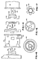
- FIG. 2 there is shown a plan view of a compressor 42, a dirve motor 44, and the coupling sleeve 46 therebetween.
- the compressor 42 is a reciprocating open drive compressor.
- the compressor has two cylinders and four cylinders.
- Gas entering the compressor at inlet 102 can range from -127°F to 85°F.
- the motor 44 is a standard NEMA D-flang motor.
- the motors used in the preferred embodiments include motors made Baldor (models 36F563W932 (5 horsepower), 37E778X118 (7.5 hp), and 37E778X234 (10 hp)), and similar capacity motors made by Marathon.
- the compressor's housing has a mouting base 104 through which two bolts 106 (one on each side of the compressor) can be inserted for supporting the compressor on platform 107 at a fixed location.
- the motor 44 also has a mounting base 108 through which bolts 110 can be inserted for supporting the motor 44 on a platform 112.
- a sleeve 46 also called a bell housing, is disengageably connected to both the compressor 42 and the motor 44 by bolts 114 and 116 which couple the flanges 118 and 120 on each end of the sleeve to corresponding flanges 122 and 124 on the motor and compressor.
- the sleeve 46 has a cylindrical interior, and two feet 126 (one on each side of the assembly) which can be bolted to a platform 128. While the sleeve is mostly closed to prevent extraneous objects from entering the sleeve, the sleeve has apertures 130 through which a socket wrench can be inserted for tightening and loosing the bolts 116 which connect the sleeve 46 to the compressor 42.
- FIG. 3 there is shown a cross section of the compressor 42, motor 44 and sleeve 46.
- the compressor's input shaft 140 and the drive motor's drive shaft 142 are connected by a coupling arrangement 145 including two coupling members 146 and 148. The manner in which these two coupling members interlock will be discussed below with reference to Figures 4 through 7.
- the first coupling member 146 is carried by the drive shaft 142 of the motor, and the second coupling member 148 is carried by the input shaft 140 of the compressor. These coupling members are interlocked in an unconnected manner with one another so that the drive shaft 142 of the motor 44 drives the input shaft 140 of the compressor 42.
- the coupling member 146 on the drive shaft 142 is a standard, motor coupling which clamps onto the drive shaft using a locked bolt bushing.
- the drive shaft 142 and coupling member 146 have at least one corresponding straight key 147 and key slot 151 for transferring torque from the drive shaft 142 to the motor coupling 146.
- the coupling member 148 connected to the input shaft 140 is a single piece of casted aluminum in the form of a flywheel which acts not only as a coupling member, but also acts as a flywheel which absorbs inertia from the compressor, reduced vibrations in the compressor, and reduced the stress placed on the compressors bearing's 149 by changing loads and motor speeds.
- the flywheel 148 is coupled to the compressor's tapered input shaft 140 by a single standard SAE threaded bolt 150 which threads into a threaded hole 152 in the shaft.
- the bolt 150 holds a washer 154 against the flywheel 148, thereby securing the flywheel to the input shaft.
- the flywheel also has a slot 156 that slides over a woodruff key 158 for transferring torque from the flywheel 148 to the input shaft 140.
- each flywheel 148 is balanced on a lathe to match the compressor that it being used with.
- the sleeve 46 is connected to the motor 44 by a set of four bolts 114 which go through a standard D flange 122 in the motor's housing into corresponding bosses 114a in the sleeve's flange 118.
- the sleeve sits on a locating shoulder 160 machined into the compressor's housing, and is held in place by a set of bolts 116 which go through a flange 120 on the inside of the sleeve 46 into corresponding bosses 116a in the compressor's housing. Access to these bolts 116 is provided by apertures 130 shown in Figure 2.
- the sleeve 46 is made of aluminum and is strong enough to support the motor 44 in a fixed position relative to the compressor for maintaining the drive shaft 142 of the motor in alignment with the input shaft 140 of the compressor when the coupling members 146 and 148 are interlocked with one another.
- the sleeve 46 is the sole means for supporting the motor so as to maintain the shafts in alignment with one another. Alignment of the two shafts takes place simply by bolting the sleeve to the compressor and motor with the flywheel and motor coupling assembly 145 inside. The sleeve bolts themselves assure proper alignment.
- Figure 4 shows the components of the coupling arrangement separated from one another along the center axis of the shafts 140 and 142. This Figure also shows the placement of the cut away views in Figures 5 through 7.
- both coupling members 148 and 146 have three spaced apart lugs 148a and 146a which interlock with the lugs on the other coupling member.
- the lugs on the coupling members are separated by a nonmetallic, compressible webbing 160 (shown in Figure 7), made from a standard chloroprene compound used in webbed motor couplings, which prevents direct metal to metal contact by the lugs, and absorbs shocks and transient torque imbalances.
- the webbing 160 has six teeth 162 which fit snugly between the lugs on both couplings.
- Figure 8 is a flow chart of the control software used in the preferred embodiment.
- the computer programs in the preferred embodiment are written in the "C” computer language, and in the assembly language for the (Intel model 8088) microprocessor used therein.
- the computer when the system is first powered up or reset (box 200) the computer performs the usual self diagnostic tests. It also checks to see if an updated version of the control software has been loaded into the RAM 74, and uses that version if the RAM passes a standard checksum test.
- the watchdog circuit resets the system, if generates signals which (1) put the system in "mechanical” mode, in which the mechanical backup system keeps the motor running, and (2) reset the controller's computer 56. If the controller 40 successfully resets itself, it puts the system back into "automatic" mode - in which the system's controller is in charge of the motor's speed.
- the controller continually performs the main loop of the control software, shown as starting at node A in Figure 8.
- the execution time of the main loop varies between 0.25 and 1.5 seconds, depending on the tasks performed.
- the initial tasks include handling keystrokes entered by the operator, updating the display, responding to communications from a host computer (i.e., communications tasks), and signalling the watchdog circuit 86 that the controller 40 is operational. Then the controller executes the compressor motor control software, starting at box 204.
- each refrigeration system 26 may have somewhat different equipment or operating conditions.
- the user specifies the set of parameters shown in Table 1. While these parameters will be discussed as they are used, some affect the overall operation of the controller.
- the parameter called "Temp_Enabled” indicates whether a temperature measurement is available for use by the controller. Since it is the goal of the controller to maintain a target temperature (called Setpt_Temp) in the application, it is clearly preferred that the system include a temperature sensor 60.
- UsePressure Another important parameter is called UsePressure. As will be described below if Temp_Enabled is false or if UsePressure is true, the controller will control the speed of the compressor's motor using an algorithm based on the pressure in the compressor's suction line. Otherwise, it will use an algorithm based on the temperature in the application. However, if both Temp_Enabled and UsePressure are true, the controller will use an algorithm that is primarily based on the suction pressure, but which floats the target pressure in accordance with the temperature in the application. Thus the controller has three different control strategies which it can use.
- the control 40 includes an interrupt generator 90 which generates an interrupt signal 120 times per second, at the peaks and valleys of the waveform of the system's 60 hertz power supply.
- Each interrupt signal causes the system to run the analog signal input routine which reads in, and keeps running averages of the temperature, suction pressure, discharge pressure, and motor speed feedback signals. These signals are converted into digital signals by the input interface 58.
- the analog input routine includes a schedule which controls which input signal is to be sampled and converted by the analog to digital converter in the interface 58 during each interrupt period.
- each cycle of sixteen interrupt calls it averages the value of each input signal measured at the time of a power waveform peak and at the time of a power waveform valley. It then computes a running average for each signal to reduce the effect of transient signal fluctuations.
- temperature is measured to an accuracy of 0.25°F
- pressure is measured to an accuracy of 0.5 psi (pounds per square inch).
- the analog input routine also acts as a timer routine which updates the "elapsed time” timer. This elapsed times is used throughout the control program for various time checks.
- the motor control software starts (at box 204) by checking for serious faults.
- the fault checking routine checks for the following faults: (1) is the discharge pressure above a specified limit "discharge_max, (2) is the suction pressure below a specified value “suction_min”, (3) is the measured temperature above or below specified limits “case_temp_max” and “case_temp_min”, (4) is the motor speed feedback signal more than fifteen percent off from the specified speed, (5) is the motor oil fault signal active, and (6) is the inverter fault signal active.
- the error is logged in the system's memory 72, noted on the display 80, and the system switches to mechanical mode - so that the mechanical backup system will take over control of the system.
- the display After checking for faults, the display is updated so that any problems detected will be shown on the display. Serious faults are also denoted by activating the buzzer 84.
- the condenser fan 31 is turned on if the discharge pressure is above FanCutIn, and its turned off if the discharge pressure is below FanCutOut. This simple fan control method saves a significant amount of energy in most air cooled systems when compared to the prior art.
- control program checks to see if the system has recently been restarted. If so, the controller's mode will be “automatic” and the controller's state will be "COLDSTART".
- the Coldstart process has three phases. First (after waiting for a defrost cycle to end, if necessary) the motor is turned on at a specified speed. CycleOn, which is typically an intermediate speed such as 750 rpms. Then, after a minute or so the controller checks that the motor speed is ramping up to the specified speed. If at the end of a specified time the motor is not within a specified margin of the CycleOn speed, the motor is shut off and the controller activates the mechanical backup system.
- CycleOn typically an intermediate speed such as 750 rpms.
- the controller waits for another short period of time, tests to see if the teperature, suction pressure and discharge pressure have moved in right direction since the beginning of the Coldstart process, and returns control to the normal control routine.
- the user can schedule up to six different times at which to start a primary defrost, and up to six other times at which to start the auxiliary defrost.
- a routine called Check_Defrost checks these schedules. If the current time corresponds to the scheduled start of a primary defrost, the primary defrost is turned on, the compressor motor is turned off, the controller's state is set to DEFROST, and the auxiliary defrost is also turned on if there is an auxiliary defrost.
- Scheduled auxiliary defrosts are different in that only the auxiliary defrost is turned on and the controller does not change operation states. Also, since auxiliary defrosts run for a specified time, this routine also turns off the auxiliary defrost at the scheduled termination time.
- the motor speed is adjusted only at specified intervals (box 214). If the time since the last execution of the motor speed adjustment process is less than SanpleTime seconds, the process goes back to node A.
- the sample time interval depends on the control strategy being used. For temperature based control, the interval is typically fifteen to thirty seconds; for pressure based control, the sample time interval is typically three to ten seconds.
- the controller checks to see if any of the defrost termination criteria have been met (box 218). There are three different criteria which can be used: a maximum defrost duration, a maximum suction line pressure, and a maximum case temperature. If defrost is not terminated, the motor is left off and the process goes back to node A.
- the controller turns on the motor at full speed (called Design_hz), sets its state to POSTDEFROST (box 220) and returns to node A.
- Design_hz The purpose of POSTDEFROST is to pull the application temperature back down to normal as quickly as possible.
- the controller remains in POSTDEFROST for at least a specified minimum time, Min_PostDefrost_Time. Then POSTDEFROST is terminated, and the controller's state is set to RESCTL (short for "restore control"), if (1) the temperature falls below a specified temperature above the target temperature; (2) the suction pressure falls below a specified suction pressure above the target suction pressure, (3) or the elapsed time is POSTDEFROST exceeds a specified time. Otherwise, the controller stays in POSTDEFROST with the motor running at full speed.
- RESCTL short for "restore control
- POSTDEFROST is terminated before the temperature and/or pressure reach their target values so that the system will smoothly reach its target rather than overshooting the target temperature and/or pressure.
- the controller will shut down the motor and set the state to CYCLEOFF (see boxes 236 and 238). Once the motor is shut off, it is kept off for at least a specified time, Min_Take_Off, to prevent the compressor from being cycled off and on too quickly. Then controller will turn the motor back at a specified speed, CycleOn, and set the state to CYCLEON if (boxes 228 and 230): the temperature rises above its target level, the suction pressure rises above its target level, or the elapsed time in CYCLEOFF exceeds a specified maximum, Max_Time_Off.
- the motor speed adjustment procedure (box 234), called PID is executed.
- This procedure is called PID because the motor speed adjustment is based on three factors, one which is Proportional to an error signal, one which is the Integral of the error signal, and one which is the derivative of the error signal.
- the error signal used is the difference between the measured suction pressure and the pressure set point Setpt_Sp. Otherwise the error signal used is the difference between the measured temperature and the temperature set point Setpt_Temp.
- Kp, Kd and Ki are constant parameters. One set of parameter values is used for temperature based control, and another is used for pressure based control.
- d ⁇ S/dt is the rate of change in the error signal ⁇ S
- ⁇ S dt is the integral of ⁇ S over a specified period of time
- Range_hz_max is the multiple used to convert the computed PID error to a speed adjustment.
- a temperature based strategy In the preferred embodiment there are actually three control strategies: a temperature based strategy, a pressure based strategy, and one which uses both temperature and pressure.
- the third strategy comes into play if both Temp_Enabled and UsePressure are true.
- the pressure control algorithm is used, but the target pressure is periodically (typically once every few minutes) increased if the measured temperature is below the target deadband, and decreased if the measured temperature is above the target deadband.
- the motor speed is not changed if the error signal falls within a specified target deadband - on the basis that if the system is on target, it should be left along as long as possible.
- the new motor speed is (1) not allowed to increase at more than a specified rate nor to decrease at more than a specified rate - to prevent unnecessary motor speed fluctuations, and (2) is kept within its specified limits, MinSpeed and Design_hz.
- the controller uses additional logic when the motor runs at its specified minimum speed (e.g. 450 rpms).
- the controller keeps the motor running at this minimum speed as long as the temperature or pressure remains within a specified deadband. But if the pressure falls below a specified low limit, or if the temperature and pressure fall below the deadband for at least a specified period of time (Min_Speed_Time, e.g., 10 minutes) the controller will turn off the compressor and enter the CYCLEOFF state.
- Min_Speed_Time e.g. 10 minutes
Landscapes
- Engineering & Computer Science (AREA)
- General Engineering & Computer Science (AREA)
- Mechanical Engineering (AREA)
- Computer Hardware Design (AREA)
- Physics & Mathematics (AREA)
- Thermal Sciences (AREA)
- Control Of Positive-Displacement Pumps (AREA)
Applications Claiming Priority (2)
| Application Number | Priority Date | Filing Date | Title |
|---|---|---|---|
| US12578 | 1987-02-09 | ||
| US07/012,578 US4765150A (en) | 1987-02-09 | 1987-02-09 | Continuously variable capacity refrigeration system |
Publications (2)
| Publication Number | Publication Date |
|---|---|
| EP0278630A2 true EP0278630A2 (de) | 1988-08-17 |
| EP0278630A3 EP0278630A3 (de) | 1990-01-17 |
Family
ID=21755628
Family Applications (1)
| Application Number | Title | Priority Date | Filing Date |
|---|---|---|---|
| EP88300659A Withdrawn EP0278630A3 (de) | 1987-02-09 | 1988-01-27 | Kälteanlage mit kontinuierlich regelbarer Leistung |
Country Status (3)
| Country | Link |
|---|---|
| US (1) | US4765150A (de) |
| EP (1) | EP0278630A3 (de) |
| CA (1) | CA1310196C (de) |
Cited By (7)
| Publication number | Priority date | Publication date | Assignee | Title |
|---|---|---|---|---|
| FR2679016A1 (fr) * | 1991-07-09 | 1993-01-15 | Sofath | Pompe a chaleur a regulation piece par piece et a puissance variable. |
| FR2789462A1 (fr) * | 1999-02-09 | 2000-08-11 | Pompes Salmson Sa | Accouplement pour pompe et moteur de pompe |
| EP1038703A3 (de) * | 1999-03-26 | 2002-06-19 | Carrier Corporation | Spannungsreglung mittels Motorgeschwindigkeit |
| WO2003019090A1 (en) * | 2001-08-29 | 2003-03-06 | Empresa Brasileira De Compressores S.A - Embraco | A cooling control system for an ambient to be cooled, a method of controlling a cooling system, and a cooler. |
| BE1015817A3 (fr) * | 2003-12-15 | 2005-09-06 | Citelec S A | Dispositif de securite et de controle pour compresseur de machine frigorifique. |
| CN106796070A (zh) * | 2014-08-29 | 2017-05-31 | 艾默生环境优化技术有限公司 | 具有声控除霜模式的变速压缩机控制 |
| EP2469090A3 (de) * | 2010-12-25 | 2017-11-22 | Max Co., Ltd. | Verdichter und Betriebsverfahren für einen Verdichter |
Families Citing this family (54)
| Publication number | Priority date | Publication date | Assignee | Title |
|---|---|---|---|---|
| US5008051A (en) * | 1989-03-01 | 1991-04-16 | Decoursey Robert T | Vacuum sizing tank with electronically controlled vacuum pressure |
| US5182826A (en) * | 1989-03-09 | 1993-02-02 | Ssi Medical Services, Inc. | Method of blower control |
| US5048302A (en) * | 1990-02-09 | 1991-09-17 | Hudson Associates, Inc. | Refrigerant system having controlled variable speed drive for compressor |
| US5271238A (en) * | 1990-09-14 | 1993-12-21 | Nartron Corporation | Environmental control system |
| US5193353A (en) * | 1991-07-05 | 1993-03-16 | Carrier Corporation | High capacity hot gas heating system for transport refrigeration system |
| US5201186A (en) * | 1991-07-11 | 1993-04-13 | Thermo King Corporation | Method of operating a transport refrigeration unit |
| US5203179A (en) * | 1992-03-04 | 1993-04-20 | Ecoair Corporation | Control system for an air conditioning/refrigeration system |
| US5230223A (en) * | 1992-03-20 | 1993-07-27 | Envirosystems Corporation | Method and apparatus for efficiently controlling refrigeration and air conditioning systems |
| US5224836A (en) * | 1992-05-12 | 1993-07-06 | Ingersoll-Rand Company | Control system for prime driver of compressor and method |
| MY119900A (en) * | 1995-03-14 | 2005-08-30 | Panasonic Corp | Refrigerating apparatus, and refrigerator control and brushless motor starter used in same |
| US6172476B1 (en) * | 1998-01-28 | 2001-01-09 | Bristol Compressors, Inc. | Two step power output motor and associated HVAC systems and methods |
| US6109048A (en) * | 1999-01-20 | 2000-08-29 | Samsung Electronics Co., Ltd. | Refrigerator having a compressor with variable compression capacity |
| US6406265B1 (en) * | 2000-04-21 | 2002-06-18 | Scroll Technologies | Compressor diagnostic and recording system |
| US6769265B1 (en) | 2003-03-12 | 2004-08-03 | Maytag Corporation | Variable speed refrigeration system |
| US7490480B2 (en) * | 2003-03-14 | 2009-02-17 | Maytag Corporation | Variable speed refrigeration system |
| KR100971320B1 (ko) * | 2003-03-25 | 2010-07-20 | 트랜스퍼시픽 소닉, 엘엘씨 | 플래시롬의 응용 프로그램 저장/실행 방법 |
| US7237395B2 (en) * | 2003-12-22 | 2007-07-03 | General Electric Company | Methods and apparatus for controlling refrigerators |
| US7451614B2 (en) * | 2004-04-01 | 2008-11-18 | Perlick Corporation | Refrigeration system and components thereof |
| US7412842B2 (en) | 2004-04-27 | 2008-08-19 | Emerson Climate Technologies, Inc. | Compressor diagnostic and protection system |
| US7275377B2 (en) | 2004-08-11 | 2007-10-02 | Lawrence Kates | Method and apparatus for monitoring refrigerant-cycle systems |
| US7481069B2 (en) * | 2005-07-28 | 2009-01-27 | Carrier Corporation | Controlling a voltage-to-frequency ratio for a variable speed drive in refrigerant systems |
| CA2637887A1 (en) * | 2005-12-07 | 2007-06-14 | Carrier Commercial Refrigeration Inc. | Airflow stabilizer for lower front of a rear loaded refrigerated display case |
| US20070289323A1 (en) * | 2006-06-20 | 2007-12-20 | Delaware Capital Formation, Inc. | Refrigerated case with low frost operation |
| US8590325B2 (en) | 2006-07-19 | 2013-11-26 | Emerson Climate Technologies, Inc. | Protection and diagnostic module for a refrigeration system |
| US20080216494A1 (en) | 2006-09-07 | 2008-09-11 | Pham Hung M | Compressor data module |
| CA2659049A1 (en) * | 2006-10-26 | 2008-05-02 | Carrier Corporation | Secondary airflow distribution for a display case |
| US8672733B2 (en) | 2007-02-06 | 2014-03-18 | Nordyne Llc | Ventilation airflow rate control |
| US8973385B2 (en) * | 2007-03-02 | 2015-03-10 | Hill Phoenix, Inc. | Refrigeration system |
| JP4916383B2 (ja) * | 2007-06-01 | 2012-04-11 | サンデン株式会社 | 電動型スクロール圧縮機の起動制御装置及びその起動制御方法 |
| US7770806B2 (en) * | 2007-06-19 | 2010-08-10 | Nordyne Inc. | Temperature control in variable-capacity HVAC system |
| US20090037142A1 (en) | 2007-07-30 | 2009-02-05 | Lawrence Kates | Portable method and apparatus for monitoring refrigerant-cycle systems |
| US8393169B2 (en) | 2007-09-19 | 2013-03-12 | Emerson Climate Technologies, Inc. | Refrigeration monitoring system and method |
| US9140728B2 (en) | 2007-11-02 | 2015-09-22 | Emerson Climate Technologies, Inc. | Compressor sensor module |
| US8160827B2 (en) | 2007-11-02 | 2012-04-17 | Emerson Climate Technologies, Inc. | Compressor sensor module |
| US8973379B2 (en) * | 2008-07-25 | 2015-03-10 | Hill Phoenix, Inc. | Refrigeration control systems and methods for modular compact chiller units |
| US9526354B2 (en) * | 2008-09-11 | 2016-12-27 | Hill Phoenix, Inc. | Air distribution system for temperature-controlled case |
| US20110162396A1 (en) * | 2008-09-29 | 2011-07-07 | Carrier Corporation | Capacity boosting during pulldown |
| US8631663B2 (en) * | 2009-04-30 | 2014-01-21 | Hill Phoenix, Inc. | Power failure controller for an electronically controlled expansion valve in a refrigeration system |
| US8863541B2 (en) * | 2009-06-10 | 2014-10-21 | Hill Phoenix, Inc. | Air distribution system for temperature-controlled case |
| US9664424B2 (en) | 2010-11-17 | 2017-05-30 | Hill Phoenix, Inc. | Cascade refrigeration system with modular ammonia chiller units |
| US9541311B2 (en) | 2010-11-17 | 2017-01-10 | Hill Phoenix, Inc. | Cascade refrigeration system with modular ammonia chiller units |
| US9657977B2 (en) | 2010-11-17 | 2017-05-23 | Hill Phoenix, Inc. | Cascade refrigeration system with modular ammonia chiller units |
| WO2012118830A2 (en) | 2011-02-28 | 2012-09-07 | Arensmeier Jeffrey N | Residential solutions hvac monitoring and diagnosis |
| US8964338B2 (en) | 2012-01-11 | 2015-02-24 | Emerson Climate Technologies, Inc. | System and method for compressor motor protection |
| US9480177B2 (en) | 2012-07-27 | 2016-10-25 | Emerson Climate Technologies, Inc. | Compressor protection module |
| US9310439B2 (en) | 2012-09-25 | 2016-04-12 | Emerson Climate Technologies, Inc. | Compressor having a control and diagnostic module |
| AU2014229103B2 (en) | 2013-03-15 | 2016-12-08 | Emerson Electric Co. | HVAC system remote monitoring and diagnosis |
| US9803902B2 (en) | 2013-03-15 | 2017-10-31 | Emerson Climate Technologies, Inc. | System for refrigerant charge verification using two condenser coil temperatures |
| US9551504B2 (en) | 2013-03-15 | 2017-01-24 | Emerson Electric Co. | HVAC system remote monitoring and diagnosis |
| US9765979B2 (en) | 2013-04-05 | 2017-09-19 | Emerson Climate Technologies, Inc. | Heat-pump system with refrigerant charge diagnostics |
| US10906374B2 (en) * | 2018-12-03 | 2021-02-02 | Ford Global Technologies, Llc | A/C compressor control using refrigerant pressure |
| JP7143272B2 (ja) * | 2019-12-24 | 2022-09-28 | ツインバード工業株式会社 | フリーピストン型スターリング冷凍機 |
| US11774127B2 (en) * | 2021-06-15 | 2023-10-03 | Honeywell International Inc. | Building system controller with multiple equipment failsafe modes |
| CN116105411B (zh) * | 2023-04-04 | 2023-07-18 | 宁波奥克斯电气股份有限公司 | 压缩机控制方法、装置、空调器及存储介质 |
Citations (6)
| Publication number | Priority date | Publication date | Assignee | Title |
|---|---|---|---|---|
| US3610781A (en) * | 1968-12-10 | 1971-10-05 | Bosch Gmbh Robert | Windshield wiper motor and pump assembly |
| DE1939410B2 (en) * | 1969-08-02 | 1975-04-03 | Harald Dr.-Ing. 6680 Neunkirchen Barth | Claw coupling with an elastic insert between two plates - has improved characteristics under heavy load |
| US4514991A (en) * | 1983-10-17 | 1985-05-07 | Carrier Corporation | Variable speed drive motor system with inverter control |
| DE3523818A1 (de) * | 1984-07-04 | 1986-01-09 | Kabushiki Kaisha Toshiba, Kawasaki, Kanagawa | Klimaanlage |
| US4622827A (en) * | 1983-12-28 | 1986-11-18 | Matsushita Electric Industrial Co., Ltd. | Control apparatus for an air conditioner |
| GB2183018A (en) * | 1985-10-28 | 1987-05-28 | Toshiba Kk | Multi-type air conditioner with optimum control for each load |
Family Cites Families (4)
| Publication number | Priority date | Publication date | Assignee | Title |
|---|---|---|---|---|
| DE2323269A1 (de) * | 1973-05-09 | 1974-11-28 | Bosch Gmbh Robert | Foerderaggregat fuer fluessigkeiten |
| US4628700A (en) * | 1979-07-31 | 1986-12-16 | Alsenz Richard H | Temperature optimizer control apparatus and method |
| US4507058A (en) * | 1983-12-20 | 1985-03-26 | Carr-Griff, Inc. | Wobble plate pump and drive mechanism therefor |
| US4676073A (en) * | 1985-06-11 | 1987-06-30 | Carl Lawrence | Cooling apparatus |
-
1987
- 1987-02-09 US US07/012,578 patent/US4765150A/en not_active Ceased
-
1988
- 1988-01-27 EP EP88300659A patent/EP0278630A3/de not_active Withdrawn
- 1988-02-08 CA CA000558339A patent/CA1310196C/en not_active Expired - Lifetime
Patent Citations (6)
| Publication number | Priority date | Publication date | Assignee | Title |
|---|---|---|---|---|
| US3610781A (en) * | 1968-12-10 | 1971-10-05 | Bosch Gmbh Robert | Windshield wiper motor and pump assembly |
| DE1939410B2 (en) * | 1969-08-02 | 1975-04-03 | Harald Dr.-Ing. 6680 Neunkirchen Barth | Claw coupling with an elastic insert between two plates - has improved characteristics under heavy load |
| US4514991A (en) * | 1983-10-17 | 1985-05-07 | Carrier Corporation | Variable speed drive motor system with inverter control |
| US4622827A (en) * | 1983-12-28 | 1986-11-18 | Matsushita Electric Industrial Co., Ltd. | Control apparatus for an air conditioner |
| DE3523818A1 (de) * | 1984-07-04 | 1986-01-09 | Kabushiki Kaisha Toshiba, Kawasaki, Kanagawa | Klimaanlage |
| GB2183018A (en) * | 1985-10-28 | 1987-05-28 | Toshiba Kk | Multi-type air conditioner with optimum control for each load |
Cited By (14)
| Publication number | Priority date | Publication date | Assignee | Title |
|---|---|---|---|---|
| FR2679016A1 (fr) * | 1991-07-09 | 1993-01-15 | Sofath | Pompe a chaleur a regulation piece par piece et a puissance variable. |
| FR2789462A1 (fr) * | 1999-02-09 | 2000-08-11 | Pompes Salmson Sa | Accouplement pour pompe et moteur de pompe |
| EP1028263A1 (de) * | 1999-02-09 | 2000-08-16 | Pompes Salmson | Kupplung für Pumpe und Motor |
| EP1038703A3 (de) * | 1999-03-26 | 2002-06-19 | Carrier Corporation | Spannungsreglung mittels Motorgeschwindigkeit |
| US7228694B2 (en) | 2001-08-29 | 2007-06-12 | Empresa Brasileira De Compressores S.A. - Embraco | Cooling control system for an ambient to be cooled, a method of controlling a cooling system, and a cooler |
| WO2003019090A1 (en) * | 2001-08-29 | 2003-03-06 | Empresa Brasileira De Compressores S.A - Embraco | A cooling control system for an ambient to be cooled, a method of controlling a cooling system, and a cooler. |
| CN1332163C (zh) * | 2001-08-29 | 2007-08-15 | 巴西压缩机股份有限公司 | 用于被冷却环境的冷却控制系统、控制冷却系统的方法、以及冷却器 |
| KR100892193B1 (ko) * | 2001-08-29 | 2009-04-07 | 월풀 에쎄.아. | 냉각될 실내의 냉각제어시스템과 냉각시스템을 제어하는방법 및 냉각기 |
| BE1015817A3 (fr) * | 2003-12-15 | 2005-09-06 | Citelec S A | Dispositif de securite et de controle pour compresseur de machine frigorifique. |
| EP2469090A3 (de) * | 2010-12-25 | 2017-11-22 | Max Co., Ltd. | Verdichter und Betriebsverfahren für einen Verdichter |
| CN106796070A (zh) * | 2014-08-29 | 2017-05-31 | 艾默生环境优化技术有限公司 | 具有声控除霜模式的变速压缩机控制 |
| EP3186101A4 (de) * | 2014-08-29 | 2018-04-18 | Emerson Climate Technologies, Inc. | Verdichter mit variabler geschwindigkeit mit schallgesteuertem enteisungsmodus |
| US10240838B2 (en) | 2014-08-29 | 2019-03-26 | Emerson Climate Technologies, Inc. | Variable speed compressor control with sound-controlled defrost mode |
| CN106796070B (zh) * | 2014-08-29 | 2020-08-07 | 艾默生环境优化技术有限公司 | 具有声控除霜模式的变速压缩机控制 |
Also Published As
| Publication number | Publication date |
|---|---|
| CA1310196C (en) | 1992-11-17 |
| EP0278630A3 (de) | 1990-01-17 |
| US4765150A (en) | 1988-08-23 |
Similar Documents
| Publication | Publication Date | Title |
|---|---|---|
| EP0278630A2 (de) | Kälteanlage mit kontinuierlich regelbarer Leistung | |
| USRE33620E (en) | Continuously variable capacity refrigeration system | |
| US5203179A (en) | Control system for an air conditioning/refrigeration system | |
| US6581399B2 (en) | Apparatus and method for controlling a magnetic bearing centrifugal chiller | |
| CN101275799B (zh) | 冷却系统 | |
| US6196012B1 (en) | Generator power management | |
| US6679072B2 (en) | Diagnostic system and method for a cooling system | |
| US5746062A (en) | Methods and apparatuses for detecting surge in centrifugal compressors | |
| US5123256A (en) | Method of compressor staging for a multi-compressor refrigeration system | |
| US6216478B1 (en) | Operation speed change system and method for refrigerator | |
| WO1988006703A1 (en) | Refrigeration systems | |
| CN100429465C (zh) | 用于商店的致冷机系统 | |
| AU2002301023B2 (en) | An adaptive control for a refrigeration system using pulse width modulated duty cycle scroll compressor | |
| JPS629153A (ja) | 冷凍装置 | |
| JPH0335519B2 (de) | ||
| CN100398962C (zh) | 冷藏系统的控制方法 | |
| RU2730197C2 (ru) | Способ управления при остановке турбомашинной технологической линии в установке для сжижения газообразного продукта | |
| JPH08121882A (ja) | 冷凍装置 | |
| IL114806A (en) | Method and system for control of cooling system | |
| AU2003248304A1 (en) | Diagnostic system for an electronic stepper regulator valve |
Legal Events
| Date | Code | Title | Description |
|---|---|---|---|
| PUAI | Public reference made under article 153(3) epc to a published international application that has entered the european phase |
Free format text: ORIGINAL CODE: 0009012 |
|
| AK | Designated contracting states |
Kind code of ref document: A2 Designated state(s): AT BE CH DE ES FR GB GR IT LI LU NL SE |
|
| PUAL | Search report despatched |
Free format text: ORIGINAL CODE: 0009013 |
|
| AK | Designated contracting states |
Kind code of ref document: A3 Designated state(s): AT BE CH DE ES FR GB GR IT LI LU NL SE |
|
| 17P | Request for examination filed |
Effective date: 19900627 |
|
| 17Q | First examination report despatched |
Effective date: 19910218 |
|
| STAA | Information on the status of an ep patent application or granted ep patent |
Free format text: STATUS: THE APPLICATION IS DEEMED TO BE WITHDRAWN |
|
| 18D | Application deemed to be withdrawn |
Effective date: 19910701 |