EP0278434A2 - A blade, especially a rotor blade - Google Patents
A blade, especially a rotor blade Download PDFInfo
- Publication number
- EP0278434A2 EP0278434A2 EP88101712A EP88101712A EP0278434A2 EP 0278434 A2 EP0278434 A2 EP 0278434A2 EP 88101712 A EP88101712 A EP 88101712A EP 88101712 A EP88101712 A EP 88101712A EP 0278434 A2 EP0278434 A2 EP 0278434A2
- Authority
- EP
- European Patent Office
- Prior art keywords
- blade
- tip
- axis
- degrees
- injection holes
- Prior art date
- Legal status (The legal status is an assumption and is not a legal conclusion. Google has not performed a legal analysis and makes no representation as to the accuracy of the status listed.)
- Granted
Links
- 238000002347 injection Methods 0.000 claims abstract description 56
- 239000007924 injection Substances 0.000 claims abstract description 56
- 239000012530 fluid Substances 0.000 claims abstract description 27
- 230000000063 preceeding effect Effects 0.000 claims 3
- 230000000694 effects Effects 0.000 abstract description 4
- 238000001816 cooling Methods 0.000 description 8
- 239000007789 gas Substances 0.000 description 5
- 239000012809 cooling fluid Substances 0.000 description 3
- 230000009291 secondary effect Effects 0.000 description 3
- 238000000926 separation method Methods 0.000 description 3
- 238000010586 diagram Methods 0.000 description 2
- 238000000034 method Methods 0.000 description 2
- 239000003082 abrasive agent Substances 0.000 description 1
- 238000002485 combustion reaction Methods 0.000 description 1
- 230000003247 decreasing effect Effects 0.000 description 1
- 230000001419 dependent effect Effects 0.000 description 1
- 230000000881 depressing effect Effects 0.000 description 1
- 238000010438 heat treatment Methods 0.000 description 1
- 230000003993 interaction Effects 0.000 description 1
- 239000000463 material Substances 0.000 description 1
- 230000002093 peripheral effect Effects 0.000 description 1
Images



Classifications
-
- F—MECHANICAL ENGINEERING; LIGHTING; HEATING; WEAPONS; BLASTING
- F01—MACHINES OR ENGINES IN GENERAL; ENGINE PLANTS IN GENERAL; STEAM ENGINES
- F01D—NON-POSITIVE DISPLACEMENT MACHINES OR ENGINES, e.g. STEAM TURBINES
- F01D5/00—Blades; Blade-carrying members; Heating, heat-insulating, cooling or antivibration means on the blades or the members
- F01D5/12—Blades
- F01D5/14—Form or construction
- F01D5/141—Shape, i.e. outer, aerodynamic form
- F01D5/145—Means for influencing boundary layers or secondary circulations
-
- F—MECHANICAL ENGINEERING; LIGHTING; HEATING; WEAPONS; BLASTING
- F01—MACHINES OR ENGINES IN GENERAL; ENGINE PLANTS IN GENERAL; STEAM ENGINES
- F01D—NON-POSITIVE DISPLACEMENT MACHINES OR ENGINES, e.g. STEAM TURBINES
- F01D11/00—Preventing or minimising internal leakage of working-fluid, e.g. between stages
- F01D11/08—Preventing or minimising internal leakage of working-fluid, e.g. between stages for sealing space between rotor blade tips and stator
- F01D11/10—Preventing or minimising internal leakage of working-fluid, e.g. between stages for sealing space between rotor blade tips and stator using sealing fluid, e.g. steam
-
- F—MECHANICAL ENGINEERING; LIGHTING; HEATING; WEAPONS; BLASTING
- F01—MACHINES OR ENGINES IN GENERAL; ENGINE PLANTS IN GENERAL; STEAM ENGINES
- F01D—NON-POSITIVE DISPLACEMENT MACHINES OR ENGINES, e.g. STEAM TURBINES
- F01D5/00—Blades; Blade-carrying members; Heating, heat-insulating, cooling or antivibration means on the blades or the members
- F01D5/12—Blades
- F01D5/14—Form or construction
- F01D5/18—Hollow blades, i.e. blades with cooling or heating channels or cavities; Heating, heat-insulating or cooling means on blades
-
- F—MECHANICAL ENGINEERING; LIGHTING; HEATING; WEAPONS; BLASTING
- F01—MACHINES OR ENGINES IN GENERAL; ENGINE PLANTS IN GENERAL; STEAM ENGINES
- F01D—NON-POSITIVE DISPLACEMENT MACHINES OR ENGINES, e.g. STEAM TURBINES
- F01D5/00—Blades; Blade-carrying members; Heating, heat-insulating, cooling or antivibration means on the blades or the members
- F01D5/12—Blades
- F01D5/14—Form or construction
- F01D5/20—Specially-shaped blade tips to seal space between tips and stator
-
- F—MECHANICAL ENGINEERING; LIGHTING; HEATING; WEAPONS; BLASTING
- F04—POSITIVE - DISPLACEMENT MACHINES FOR LIQUIDS; PUMPS FOR LIQUIDS OR ELASTIC FLUIDS
- F04D—NON-POSITIVE-DISPLACEMENT PUMPS
- F04D29/00—Details, component parts, or accessories
- F04D29/66—Combating cavitation, whirls, noise, vibration or the like; Balancing
- F04D29/68—Combating cavitation, whirls, noise, vibration or the like; Balancing by influencing boundary layers
- F04D29/681—Combating cavitation, whirls, noise, vibration or the like; Balancing by influencing boundary layers especially adapted for elastic fluid pumps
- F04D29/684—Combating cavitation, whirls, noise, vibration or the like; Balancing by influencing boundary layers especially adapted for elastic fluid pumps by fluid injection
Definitions
- the present invention relates generally to blades used for example in turbomachinery and particularly to an improved turbine rotor blade.
- a gap between the rotor and the casing exists in all turbomachinery such as gas turbine engines, compressors, radial compressors or pumps. Furthermore the minimum size of this gap is dictated by different rates of thermal expansion and radial growth of the blades and the casing during different operational conditions. It is well established that greater operating efficiency and power output of a turbomachinery may be achieved by any means reducing the tip leakage flow, controlling the boundary layer, and increasing inlet operation temperatures.
- the tip leakage flow is the largest single source of energy loss in a turbomachine.
- the interaction of leakage flow, blade, and annulus wall boundary layers and radial transport of mass, momentum and energy results in a highly complex flow field near the tip region of a turbomachine.
- a further idea to reduce the tip leakage flow is the so called active clearance control. Thereby, the clearance or gap between the tip of the rotor blade and the casing of a turbine engine is maintained at a minimum by cooling or heating the casing of the turbo engine.
- a cooling fluid flows through openings arranged in the tip surface of the blade and is directed against the tip side wall surfaces in a plane perpendicular to the side walls.
- An object of the invention is an improved configuration for a blade, especially a rotor blade in a turbine engine, by which the energy loss in the turbo engine is significantly reduced.
- a further object of the invention is to reduce the tip leakage flow and to influence the complex flow field, thereby to reduce the corner separation zones and the energy losses produced by the complex flow field along the rotor blade.
- Yet another object of the present invention is to cool the surfaces of the rotor blade, and its root.
- the blade comprises elongated injection holes on the blade tip surface, the axes of said holes forming angles less than 90 degrees with the radial axis of the blade and having a component in the direction of the local chordline of the tip surface.
- chordline is approximately parallel to the main flow direction of the working gas along the rotor blade.
- the injection holes are generally arranged in the tip surface over the whole length thereof between the leading and the trailing edge of the blade. The main flow is thereby diverted in such a manner that no tip leakage flow occurs.
- Similar injection holes may be provided in the sidewalls of the blade near the tip and the root regions and in the root portion of the blade. The fluid passing through these holes supports the reduction of the tip leakage flow and/or smooth the flow of the working fluid and make it more uniform.
- tip leakage flow and the boundery layer on a blade as well as the corner separation zones may be controlled by this specific injection or suction arrangement located at the tip plane and at airfoil sections close to the tip and root plane, respectively, and at the root plane close to the airfoil section.
- the nature of this tip leakage and boundary control structure is based on an air-curtain effect interwoven with an entrainment effect which reduces the tip leakage flow as well or controls the boundary layer in such a fashion that the efficiency of the stage increases and the flow field behind the blade is more uniform.
- Such arrangements may also provide cooling in addition to decreasing tip leakage flow and boundary layer control.
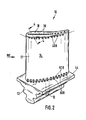
- Fig. 1 and 2 depict a blade 10 comprising a root portion 12 and a hollow airfoil portion 14.
- the airfoil portion 14 of the blade 10 is contoured to define a concave side 16, a convex side 17, and has a blade tip 18.
- the root portion 12 of the blade 10 secures the blade in a rotor disc (not shown) attached rigidly thereto and includes an inlet port 13 leading to various elongate injection holes 30, 40A, 40B, 50A, 50B, 60A and 60B.
- the main flow direction of a working fluid is designated as MF.
- the blade 10 has a generally flat surface 19 at the blade tip 18 structured to prevent tip leakage flow driven from the pressure 16 to the suction side 17 of blade 10, crossing the blade tip 18.
- a radially extending collar may be provided along the border lines of the tip surface 19 to increase the flow resistance between pressure and suction side.
- the blade tip 18 of the rotor blade 10 comprises a plurality of elongate injection holes 30, arranged in a pattern, for example as shown in a row along a chordline C of the tip surface 19, running from the leading to the trailing edge of the blade.
- the injection holes 30 should be arranged over the whole peripheral length of the rotor blade 10.
- the fluid support for the injection running through hollow airfoil portion 14 enters at inlet port 13.
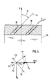
- the axes A of the elongated injection holes 30 are inclined with respect to the radial axis X of the blade under angles alpha less than 90 degrees. In this embodiment the angle is 45 degrees. Preferred values of this angle are between 15 and 75 degrees.
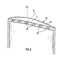
- the detail of the injection holes 30 is shown in Fig. 3 and 4.
- the local direction of the chordline is designated as Y in the diagram of figure 4, the direction perpendicular thereto and perpendicular to the radial axis X as Z.
- the axis A of an injection hole preferably lies in the plane X-Y, so that the fluid F flows upwards with a component F Y in the local direction of the chordline leading to the trailing edge of the rotor blade.
- the injection holes 30 thus provide means for controlling the boundary layer of blade 10 at the blade tip 18 and thus means for depressing the tip leakage flow crossing the blade tip 18, and the vortices close to blade tip 18.
- the blade 10 further comprises a plurality of injection holes 40A on the concave side 16 close to blade tip 18 and a plurality of injection holes 40B close to blade tip 18 on the convex side 17.
- the axes of the injection holes 40A on the pressure side and the holes 40B on the suction side form an angle less than 90 degrees between the radial extended tip plane and the perpendicular on the outer wall respectively. They have a component in the direction of the local main flow MF.
- the fluid passing through the injection holes 40A and 40B is directed upwards towards the trailing edge of the blade.
- the holes 40A, 40B may be directed towards the leading edge of the blade so that the working fluid may enter into the hollow plenum of the airfoil portion 14.
- the fluid for the injection coming from hollow airfoil portion 14 enters at inlet port 13.
- the detail of the injection holes 40A and 40B and 50A and 50B and 60A and 60B is shown in Fig. 5.
- holes 40A, 40B, 50A and 50B do not appear to extend to the hollow portion of the blade 18 because of the angle which they make with the plane of the drawings. These holes do, however, communicate with the hollow plenum.
- the injection holes 40A and 40B thus provide means for controlling the boundary layer and vortices close to the tip on the concave side 16 and the convex side 17, respectively. Moreover, the effect of reducing the tip leakage flow is supported. As shown, the axes of these holes form angles of less than 90 degrees with both the normal to the local plane of the rotor and with the radial axis of the rotor. The axes of those holes are not normal to the local plane of rotor.
- blade 10 includes a plurality of injection holes 50A and 50B close to the root plane 44 on the concave side 16 and the convex side 17 respectively.
- the axes of the injection holes 50A and 50B are directed towards the blade root 44 and form angles less than 90 degrees with the local plane of the concave side 16 and the convex side 17, respectively. These axes are, however, not normal to the local surface plane.
- the axes of the elongate holes also form an angle of less than 90 degrees with the radial axis of the rotor.
- the fluid for the injection comes from the hollow airfoil portion 14 and enters the hollow plenum at said inlet port 13.
- the horizontal detail of the injection holes 50A and 50B is shown in Fig. 7.
- the injection holes 50A and 50B thus provide means for controlling the boundary layer and vortices close to the root plane on the concave side 16 and the convex side 17, respectively.
- Blade 10 also comprises a plurality of elongate injection holes 60A and 60B close to the concave side 16 an the convex side 17 on the root plane 44.
- the elongate injection holes 60A and 60B are directed towards the side walls 16, 17 of the blade under angles less than 90 degree with the local perpendicular of the root plane 44.
- the fluid for the injection enters at inlet port 13.
- the detail of the injection holes 60A and 60B is shown in Fig. 5.
- the injection holes 60A and 60B thus provide means for controlling the boundary layer and vortices close to the root plane 44 on the concave side 16 and the convex side 17, respectively.
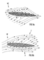
- Figure 9a shows the qualitative behavior of the main flow MF along a test standard blade 10 in the tip region.
- a fluid -short arrows F- is injected in the main flow between the pressure and suction side and directed upwards towards the trailing edge of the blade, with a component in the chordline C.
- the mainflow MF is diverted in the direction of the fluid flow F. No tip leakage flow occurs. Furthermore, the main flow is smoothed so that the secondary effects in the flow field, such as vortices and distortions in the boundary layer region, are significantly reduced.
- the volume of fluid injection through the holes into the gap region has a value between 0,05 % and 0,4 % of the working fluid volume, dependent on the configuration of the blade and the casing. Best results for a blade as shown in figures 1 and 2 may be achieved for values between 0,15 % and 0,25 %.
- a conventional standard rotor blade having no injection holes arranged and directed as in fig. 9a produces a significant leakage flow LF between the pressure side P and the suction side S of the main flow MF interwoven with secondary effects. It is to be pointed out that the occurrence of leakage flow LF cannot be suppressed even if a fluid is blown into the gap region radially or in a plane perpendicular to the local chordline as known in the state of the art for cooling purpose.
- the invention may be used for example to reduce the leakage flow between a stator with adjustable guide vanes and a rotating shaft and to improve the secondary effects of the main flow as explained above.
Landscapes
- Engineering & Computer Science (AREA)
- Mechanical Engineering (AREA)
- General Engineering & Computer Science (AREA)
- Physics & Mathematics (AREA)
- Fluid Mechanics (AREA)
- Turbine Rotor Nozzle Sealing (AREA)
- Structures Of Non-Positive Displacement Pumps (AREA)
Abstract
Description
- The present invention relates generally to blades used for example in turbomachinery and particularly to an improved turbine rotor blade.
- A gap between the rotor and the casing exists in all turbomachinery such as gas turbine engines, compressors, radial compressors or pumps. Furthermore the minimum size of this gap is dictated by different rates of thermal expansion and radial growth of the blades and the casing during different operational conditions. It is well established that greater operating efficiency and power output of a turbomachinery may be achieved by any means reducing the tip leakage flow, controlling the boundary layer, and increasing inlet operation temperatures.
- The tip leakage flow is the largest single source of energy loss in a turbomachine. The interaction of leakage flow, blade, and annulus wall boundary layers and radial transport of mass, momentum and energy results in a highly complex flow field near the tip region of a turbomachine.
- In order to reduce the tip leakage flow several ideas have been used such as the cutting of grooves, squellers, or the use of abrasive materials applied either on the blade tip or on the casing, in order to obtain the smallest possible clearance and thereby reduce the leakage flow by increasing the flow resistance in the tip region from the pressure to the suction side. Such structures are described in greater detail in U.S. Pat. Nos. 4 589 823 and 4 571 937.
- A further idea to reduce the tip leakage flow is the so called active clearance control. Thereby, the clearance or gap between the tip of the rotor blade and the casing of a turbine engine is maintained at a minimum by cooling or heating the casing of the turbo engine.
- Futhermore, other problems exist:
The high temperatures downstream of the combustion chamber in a gas turbine require cooled rotor blades due to material constraints. The structures providing cooling for the turbine blades have generally a cooling fluid entrance at the root of the blade structure and exhaust exits located at the trailing edge, leading edge and at the tip plane of the blade. These exhaust exits are used to get rid of the cooling fluid or to produce a film of cooling air as in U.S. Pat. Nos. 4 601 638. Hill, Liang, and Auxier in U.S. Patent 4 601 638 teach the use of air holes to provide cooling, the air holes having axes which run parallel to the plane of the blade tip. Further structures are described in greater detail in U.S. Pat. Nos. 4 424 001, 4 540 339 and 4 606 701. - According to U.S. Patent No. 4 540 339 for example a cooling fluid flows through openings arranged in the tip surface of the blade and is directed against the tip side wall surfaces in a plane perpendicular to the side walls.
- In U.S. Patent 4 040 767 a coolable nozzle guide vane in the turbine section of a gas turbine engine is disclosed. Cooling air flows out of orifices in the blade side walls and the blade root and is distributed about the walls of the sections which are in contact with the hot working gases flowing through the turbine during operation of the engine.
- All these purposes provide cooling of the rotor blade and other sections. However, they do not influence or reduce the tip leakage flow and the corner separation zones.
- An object of the invention is an improved configuration for a blade, especially a rotor blade in a turbine engine, by which the energy loss in the turbo engine is significantly reduced.
- A further object of the invention is to reduce the tip leakage flow and to influence the complex flow field, thereby to reduce the corner separation zones and the energy losses produced by the complex flow field along the rotor blade.
- Yet another object of the present invention is to cool the surfaces of the rotor blade, and its root.
- In accordance with the invention the blade comprises elongated injection holes on the blade tip surface, the axes of said holes forming angles less than 90 degrees with the radial axis of the blade and having a component in the direction of the local chordline of the tip surface. In turbo engines the chordline is approximately parallel to the main flow direction of the working gas along the rotor blade. The injection holes are generally arranged in the tip surface over the whole length thereof between the leading and the trailing edge of the blade. The main flow is thereby diverted in such a manner that no tip leakage flow occurs.
- Similar injection holes may be provided in the sidewalls of the blade near the tip and the root regions and in the root portion of the blade. The fluid passing through these holes supports the reduction of the tip leakage flow and/or smooth the flow of the working fluid and make it more uniform.
- It has been found that tip leakage flow and the boundery layer on a blade as well as the corner separation zones may be controlled by this specific injection or suction arrangement located at the tip plane and at airfoil sections close to the tip and root plane, respectively, and at the root plane close to the airfoil section. The nature of this tip leakage and boundary control structure is based on an air-curtain effect interwoven with an entrainment effect which reduces the tip leakage flow as well or controls the boundary layer in such a fashion that the efficiency of the stage increases and the flow field behind the blade is more uniform. Such arrangements may also provide cooling in addition to decreasing tip leakage flow and boundary layer control.
- In turbine engines the fluid is blasted out of the injection holes. Nevertheless, in some arrangements, for example in pumps or compressors a fluid, namely the working fluid, may be sucked in the injection holes.
- The foregoing and other objections, features and advantages of the present invention will become more apparent in the light of the following detailed description of prefered embodiments thereof as shown in the accompanying drawing.
-
- Figure 1 is a perspective view of a rotor blade according to the invention taken from the concave side thereof;
- Figure 2 is a perspective view of the rotor blade taken from the convex side thereof;
- Figure 3 is a vertical crossection of the rotor blade from the leading to the trailing edge of the tip plane therof;
- Figure 4 is a detail of figure 3 showing injection holes in the tip surface and a diagram for the direction of the axes of the injection holes;
- Figure 5 is a vertical crossection of the rotor blade from the tip to the root thereof;
- Figure 6 is a horizontal crossection of the rotor blade adjacent to the tip thereof;
- Figure 7 is a horizontal crossection of the rotor bladeadjacent to the root thereof;
- Figure 8 is a vertical section through the root of the rotor blade;
- Figures 9a and 9b show the qualitative behavior of the flow near the tip clearance of a standard rotor blade with injection of a fluid into the main stream flow according to the invention and without injection, respectively.
- Fig. 1 and 2 depict a
blade 10 comprising aroot portion 12 and ahollow airfoil portion 14. Theairfoil portion 14 of theblade 10 is contoured to define aconcave side 16, aconvex side 17, and has ablade tip 18. Theroot portion 12 of theblade 10 secures the blade in a rotor disc (not shown) attached rigidly thereto and includes aninlet port 13 leading to variouselongate injection holes - In accordance with the principles of the invention, the
blade 10 has a generallyflat surface 19 at theblade tip 18 structured to prevent tip leakage flow driven from thepressure 16 to thesuction side 17 ofblade 10, crossing theblade tip 18. As known, a radially extending collar may be provided along the border lines of thetip surface 19 to increase the flow resistance between pressure and suction side. Theblade tip 18 of therotor blade 10 comprises a plurality ofelongate injection holes 30, arranged in a pattern, for example as shown in a row along a chordline C of thetip surface 19, running from the leading to the trailing edge of the blade. Theinjection holes 30 should be arranged over the whole peripheral length of therotor blade 10. The fluid support for the injection running throughhollow airfoil portion 14 enters atinlet port 13. The axes A of theelongated injection holes 30 are inclined with respect to the radial axis X of the blade under angles alpha less than 90 degrees. In this embodiment the angle is 45 degrees. Preferred values of this angle are between 15 and 75 degrees. The detail of theinjection holes 30 is shown in Fig. 3 and 4. - The local direction of the chordline is designated as Y in the diagram of figure 4, the direction perpendicular thereto and perpendicular to the radial axis X as Z. The axis A of an injection hole preferably lies in the plane X-Y, so that the fluid F flows upwards with a component FY in the local direction of the chordline leading to the trailing edge of the rotor blade.
- However, deviations from that flow direction are allowed as shown by the broken lines F1 to F5 showing the components of fluid flows in the Z-Y-plane. These flow directions each have a component in the Y-direction either directed to the trailing edge (F1 and F2) or to the leading edge (F3, F4 and F5) of the rotor blade. Only the component F1Y is shown. The angle between the Y-direction and the direction of the flow in the Z-Y-plane is less than 90 degrees, preferably less than 60 degrees. For a turbine engine the best results are achieved when the fluid flow F lies in the local X-Y-plane and is directed towards the trailing edge with the component FY. A direction of the axes towards the leading edge of the blade may be advantageous in case that fluid is sucked in the injection holes, for example in pumps.
- The injection holes 30 thus provide means for controlling the boundary layer of
blade 10 at theblade tip 18 and thus means for depressing the tip leakage flow crossing theblade tip 18, and the vortices close toblade tip 18. - The
blade 10 further comprises a plurality ofinjection holes 40A on theconcave side 16 close toblade tip 18 and a plurality of injection holes 40B close toblade tip 18 on theconvex side 17. The axes of the injection holes 40A on the pressure side and theholes 40B on the suction side form an angle less than 90 degrees between the radial extended tip plane and the perpendicular on the outer wall respectively. They have a component in the direction of the local main flow MF. In an injection process such as in a turbine engine the fluid passing through the injection holes 40A and 40B is directed upwards towards the trailing edge of the blade. In a suction process such as in a pump theholes airfoil portion 14. The fluid for the injection coming fromhollow airfoil portion 14 enters atinlet port 13. The detail of the injection holes 40A and 40B and 50A and 50B and 60A and 60B is shown in Fig. 5. In this figure as well as in figures 6 and 7holes blade 18 because of the angle which they make with the plane of the drawings. These holes do, however, communicate with the hollow plenum. The injection holes 40A and 40B thus provide means for controlling the boundary layer and vortices close to the tip on theconcave side 16 and theconvex side 17, respectively. Moreover, the effect of reducing the tip leakage flow is supported. As shown, the axes of these holes form angles of less than 90 degrees with both the normal to the local plane of the rotor and with the radial axis of the rotor. The axes of those holes are not normal to the local plane of rotor. - As shown in figures 5 and 7
blade 10 includes a plurality ofinjection holes root plane 44 on theconcave side 16 and theconvex side 17 respectively. As shown the axes of the injection holes 50A and 50B are directed towards theblade root 44 and form angles less than 90 degrees with the local plane of theconcave side 16 and theconvex side 17, respectively. These axes are, however, not normal to the local surface plane. The axes of the elongate holes also form an angle of less than 90 degrees with the radial axis of the rotor. The fluid for the injection comes from thehollow airfoil portion 14 and enters the hollow plenum at saidinlet port 13. The horizontal detail of the injection holes 50A and 50B is shown in Fig. 7. The injection holes 50A and 50B thus provide means for controlling the boundary layer and vortices close to the root plane on theconcave side 16 and theconvex side 17, respectively. -
Blade 10 also comprises a plurality ofelongate injection holes concave side 16 an theconvex side 17 on theroot plane 44. Theelongate injection holes side walls root plane 44. The fluid for the injection enters atinlet port 13. The detail of the injection holes 60A and 60B is shown in Fig. 5. The injection holes 60A and 60B thus provide means for controlling the boundary layer and vortices close to theroot plane 44 on theconcave side 16 and theconvex side 17, respectively. - Figure 9a shows the qualitative behavior of the main flow MF along a
test standard blade 10 in the tip region. - Through injection holes as shown in fig. 4 a fluid -short arrows F- is injected in the main flow between the pressure and suction side and directed upwards towards the trailing edge of the blade, with a component in the chordline C.
- The mainflow MF is diverted in the direction of the fluid flow F. No tip leakage flow occurs. Furthermore, the main flow is smoothed so that the secondary effects in the flow field, such as vortices and distortions in the boundary layer region, are significantly reduced. The volume of fluid injection through the holes into the gap region has a value between 0,05 % and 0,4 % of the working fluid volume, dependent on the configuration of the blade and the casing. Best results for a blade as shown in figures 1 and 2 may be achieved for values between 0,15 % and 0,25 %.
- In contrary, a conventional standard rotor blade having no injection holes arranged and directed as in fig. 9a produces a significant leakage flow LF between the pressure side P and the suction side S of the main flow MF interwoven with secondary effects. It is to be pointed out that the occurrence of leakage flow LF cannot be suppressed even if a fluid is blown into the gap region radially or in a plane perpendicular to the local chordline as known in the state of the art for cooling purpose.
- The invention may be used for example to reduce the leakage flow between a stator with adjustable guide vanes and a rotating shaft and to improve the secondary effects of the main flow as explained above.
Claims (16)
a root portion (12), an airfoil portion (14) having walls (16, 17) contoured to define concave and convex sides for intercepting a main flow of fluid (MF);
a hollow plenum defined within and communicating between root and airfoil portions (12, 14) for supporting the flow of a fluid therethrough; and
a blade tip (18) having on its surface (19) a plurality of elongated injection holes (30), the axes (A) of said holes (30) forming angles (alpha) less than 90 degrees with the radial axis (X) of the blade (10) and having a component (FY, F1Y) in the direction of the local chordline (C, Y) of the tip surface (19), thereby reducing the tip leakage flow and controlling the boundary layer in the vicinity of the tip region.
Applications Claiming Priority (2)
| Application Number | Priority Date | Filing Date | Title |
|---|---|---|---|
| US1178887A | 1987-02-06 | 1987-02-06 | |
| US11788 | 1987-02-06 |
Publications (3)
| Publication Number | Publication Date |
|---|---|
| EP0278434A2 true EP0278434A2 (en) | 1988-08-17 |
| EP0278434A3 EP0278434A3 (en) | 1990-01-31 |
| EP0278434B1 EP0278434B1 (en) | 1994-07-20 |
Family
ID=21751969
Family Applications (1)
| Application Number | Title | Priority Date | Filing Date |
|---|---|---|---|
| EP88101712A Expired - Lifetime EP0278434B1 (en) | 1987-02-06 | 1988-02-05 | A blade, especially a rotor blade |
Country Status (2)
| Country | Link |
|---|---|
| EP (1) | EP0278434B1 (en) |
| DE (1) | DE3850681T2 (en) |
Cited By (7)
| Publication number | Priority date | Publication date | Assignee | Title |
|---|---|---|---|---|
| TR23589A (en) * | 1988-08-24 | 1990-04-19 | United Technologies Corp | Hidden |
| WO1994012765A1 (en) * | 1992-11-24 | 1994-06-09 | United Technologies Corporation | Rotor blade with cooled integral platform |
| DE4003802A1 (en) * | 1988-08-24 | 1998-01-15 | United Technologies Corp | Axial flow turbine for gas turbine engine |
| GB2319567A (en) * | 1988-07-29 | 1998-05-27 | United Technologies Corp | Clearance control for the turbine of a gas turbine engine |
| EP1491722A3 (en) * | 2003-06-24 | 2006-05-24 | Siemens Power Generation, Inc. | Cooling of combustion turbine airfoil fillets |
| EP1793089A2 (en) | 2005-11-30 | 2007-06-06 | General Electric Company | Method and apparatus for reducing axial compressor blade tip flow |
| CN110863864A (en) * | 2019-12-11 | 2020-03-06 | 沈阳航空航天大学 | Turbine blade with transversely-meandering alternately-shrinking and-expanding short channels inside |
Families Citing this family (2)
| Publication number | Priority date | Publication date | Assignee | Title |
|---|---|---|---|---|
| DE10305351A1 (en) * | 2003-02-10 | 2004-08-19 | Rolls-Royce Deutschland Ltd & Co Kg | Compressor blade has in radially outer blade end one or more indentations in one or more rows |
| DE10355241A1 (en) * | 2003-11-26 | 2005-06-30 | Rolls-Royce Deutschland Ltd & Co Kg | Fluid flow machine with fluid supply |
Family Cites Families (5)
| Publication number | Priority date | Publication date | Assignee | Title |
|---|---|---|---|---|
| DE1024754B (en) * | 1956-02-11 | 1958-02-20 | Maschf Augsburg Nuernberg Ag | Cooled blade for hot operated turbines or compressors |
| US4020538A (en) * | 1973-04-27 | 1977-05-03 | General Electric Company | Turbomachinery blade tip cap configuration |
| US4214355A (en) * | 1977-12-21 | 1980-07-29 | General Electric Company | Method for repairing a turbomachinery blade tip |
| US4390320A (en) * | 1980-05-01 | 1983-06-28 | General Electric Company | Tip cap for a rotor blade and method of replacement |
| NO811830L (en) * | 1980-06-05 | 1981-12-07 | United Technologies Corp | REMOVABLE, CHILLABLE SUPPLY FOR ROTOR BLADES. |
-
1988
- 1988-02-05 EP EP88101712A patent/EP0278434B1/en not_active Expired - Lifetime
- 1988-02-05 DE DE3850681T patent/DE3850681T2/en not_active Expired - Fee Related
Cited By (12)
| Publication number | Priority date | Publication date | Assignee | Title |
|---|---|---|---|---|
| GB2319567A (en) * | 1988-07-29 | 1998-05-27 | United Technologies Corp | Clearance control for the turbine of a gas turbine engine |
| GB2319567B (en) * | 1988-07-29 | 1998-09-23 | United Technologies Corp | Clearance control for the turbine of a gas turbine engine |
| TR23589A (en) * | 1988-08-24 | 1990-04-19 | United Technologies Corp | Hidden |
| DE4003802A1 (en) * | 1988-08-24 | 1998-01-15 | United Technologies Corp | Axial flow turbine for gas turbine engine |
| DE4003802C2 (en) * | 1988-08-24 | 2001-12-13 | United Technologies Corp | Minimal leakage flow between the tip of the blade and the opposite housing wall |
| WO1994012765A1 (en) * | 1992-11-24 | 1994-06-09 | United Technologies Corporation | Rotor blade with cooled integral platform |
| EP1491722A3 (en) * | 2003-06-24 | 2006-05-24 | Siemens Power Generation, Inc. | Cooling of combustion turbine airfoil fillets |
| EP1793089A2 (en) | 2005-11-30 | 2007-06-06 | General Electric Company | Method and apparatus for reducing axial compressor blade tip flow |
| JP2007154887A (en) * | 2005-11-30 | 2007-06-21 | General Electric Co <Ge> | Method and turbine machine for reducing axial compressor blade tip flow |
| EP1793089A3 (en) * | 2005-11-30 | 2007-10-24 | General Electric Company | Method and apparatus for reducing axial compressor blade tip flow |
| CN110863864A (en) * | 2019-12-11 | 2020-03-06 | 沈阳航空航天大学 | Turbine blade with transversely-meandering alternately-shrinking and-expanding short channels inside |
| CN110863864B (en) * | 2019-12-11 | 2022-05-10 | 沈阳航空航天大学 | A turbine blade with transversely meandering alternately narrowing and expanding channels inside |
Also Published As
| Publication number | Publication date |
|---|---|
| DE3850681D1 (en) | 1994-08-25 |
| DE3850681T2 (en) | 1995-03-09 |
| EP0278434A3 (en) | 1990-01-31 |
| EP0278434B1 (en) | 1994-07-20 |
Similar Documents
| Publication | Publication Date | Title |
|---|---|---|
| US4863348A (en) | Blade, especially a rotor blade | |
| US6142739A (en) | Turbine rotor blades | |
| US3527543A (en) | Cooling of structural members particularly for gas turbine engines | |
| US7118329B2 (en) | Tip sealing for a turbine rotor blade | |
| US4604031A (en) | Hollow fluid cooled turbine blades | |
| US6174135B1 (en) | Turbine blade trailing edge cooling openings and slots | |
| US3726604A (en) | Cooled jet flap vane | |
| JP4152184B2 (en) | Turbine platform with descending stage | |
| US7364404B2 (en) | Turbomachine with fluid removal | |
| US5238364A (en) | Shroud ring for an axial flow turbine | |
| EP0330601B1 (en) | Cooled gas turbine blade | |
| US20060153673A1 (en) | Turbomachine exerting dynamic influence on the flow | |
| US20060067821A1 (en) | Methods and apparatus for aerodynamically self-enhancing rotor blades | |
| US11933193B2 (en) | Turbine engine with an airfoil having a set of dimples | |
| JPH10274001A (en) | Turbulence promoting structure of blade cooling passage in gas turbine engine | |
| JP2003065299A (en) | Compressor assembly of gas turbine engine | |
| US12421853B2 (en) | Turbine engine with reduced cross flow airfoils | |
| JPS60206903A (en) | Turbine power blade | |
| US6832893B2 (en) | Blade passive cooling feature | |
| US20170145828A1 (en) | Turbine blade with airfoil tip vortex control | |
| EP0473536A1 (en) | High temperature leading edge vane insert | |
| JP2000161004A (en) | Airfoil leading edge isolation cooling | |
| GB2127105A (en) | Improvements in cooled gas turbine engine aerofoils | |
| JPH09195705A (en) | Axial turbine blade | |
| EP0278434B1 (en) | A blade, especially a rotor blade |
Legal Events
| Date | Code | Title | Description |
|---|---|---|---|
| PUAI | Public reference made under article 153(3) epc to a published international application that has entered the european phase |
Free format text: ORIGINAL CODE: 0009012 |
|
| AK | Designated contracting states |
Kind code of ref document: A2 Designated state(s): CH DE FR GB IT LI SE |
|
| PUAL | Search report despatched |
Free format text: ORIGINAL CODE: 0009013 |
|
| AK | Designated contracting states |
Kind code of ref document: A3 Designated state(s): CH DE FR GB IT LI SE |
|
| 17P | Request for examination filed |
Effective date: 19900726 |
|
| 17Q | First examination report despatched |
Effective date: 19910529 |
|
| GRAA | (expected) grant |
Free format text: ORIGINAL CODE: 0009210 |
|
| AK | Designated contracting states |
Kind code of ref document: B1 Designated state(s): CH DE FR GB IT LI SE |
|
| PG25 | Lapsed in a contracting state [announced via postgrant information from national office to epo] |
Ref country code: LI Effective date: 19940720 Ref country code: CH Effective date: 19940720 |
|
| REF | Corresponds to: |
Ref document number: 3850681 Country of ref document: DE Date of ref document: 19940825 |
|
| ITF | It: translation for a ep patent filed | ||
| REG | Reference to a national code |
Ref country code: CH Ref legal event code: PL |
|
| ET | Fr: translation filed | ||
| EAL | Se: european patent in force in sweden |
Ref document number: 88101712.3 |
|
| PLBE | No opposition filed within time limit |
Free format text: ORIGINAL CODE: 0009261 |
|
| STAA | Information on the status of an ep patent application or granted ep patent |
Free format text: STATUS: NO OPPOSITION FILED WITHIN TIME LIMIT |
|
| PGFP | Annual fee paid to national office [announced via postgrant information from national office to epo] |
Ref country code: FR Payment date: 19950619 Year of fee payment: 9 |
|
| 26N | No opposition filed | ||
| PGFP | Annual fee paid to national office [announced via postgrant information from national office to epo] |
Ref country code: GB Payment date: 19960205 Year of fee payment: 9 |
|
| PGFP | Annual fee paid to national office [announced via postgrant information from national office to epo] |
Ref country code: SE Payment date: 19960228 Year of fee payment: 9 |
|
| PGFP | Annual fee paid to national office [announced via postgrant information from national office to epo] |
Ref country code: DE Payment date: 19960403 Year of fee payment: 9 |
|
| PG25 | Lapsed in a contracting state [announced via postgrant information from national office to epo] |
Ref country code: GB Effective date: 19970205 |
|
| PG25 | Lapsed in a contracting state [announced via postgrant information from national office to epo] |
Ref country code: SE Effective date: 19970206 |
|
| GBPC | Gb: european patent ceased through non-payment of renewal fee |
Effective date: 19970205 |
|
| PG25 | Lapsed in a contracting state [announced via postgrant information from national office to epo] |
Ref country code: FR Effective date: 19971030 |
|
| PG25 | Lapsed in a contracting state [announced via postgrant information from national office to epo] |
Ref country code: DE Effective date: 19971101 |
|
| EUG | Se: european patent has lapsed |
Ref document number: 88101712.3 |
|
| REG | Reference to a national code |
Ref country code: FR Ref legal event code: ST |
|
| PG25 | Lapsed in a contracting state [announced via postgrant information from national office to epo] |
Ref country code: IT Free format text: LAPSE BECAUSE OF NON-PAYMENT OF DUE FEES;WARNING: LAPSES OF ITALIAN PATENTS WITH EFFECTIVE DATE BEFORE 2007 MAY HAVE OCCURRED AT ANY TIME BEFORE 2007. THE CORRECT EFFECTIVE DATE MAY BE DIFFERENT FROM THE ONE RECORDED. Effective date: 20050205 |
|
| REG | Reference to a national code |
Ref country code: SK Ref legal event code: SPCT Owner name: MERUS LABS LUXCO SARL, LU Free format text: PRODUCT NAME: HYDROBROMID (S)-2-{1-[2-(2,3-DIHYDROBENZOFURAN-5-YL)ETYL]-3--PYROLIDINYL}-2,2-DIFENYLACETAMIDU; REGISTRATION NO/DATE: EU/1/04/294/001-012 20041022; FORMER OWNER: NOVARTIS INTERNATIONAL PHARMACEUTICAL LTD. Spc suppl protection certif: 26 5002-2005 Filing date: 20050401 Expiry date: 20150317 |