EP0277425A1 - Armature allongée - Google Patents
Armature allongée Download PDFInfo
- Publication number
- EP0277425A1 EP0277425A1 EP87310962A EP87310962A EP0277425A1 EP 0277425 A1 EP0277425 A1 EP 0277425A1 EP 87310962 A EP87310962 A EP 87310962A EP 87310962 A EP87310962 A EP 87310962A EP 0277425 A1 EP0277425 A1 EP 0277425A1
- Authority
- EP
- European Patent Office
- Prior art keywords
- blank
- elongate
- short
- slots
- series
- Prior art date
- Legal status (The legal status is an assumption and is not a legal conclusion. Google has not performed a legal analysis and makes no representation as to the accuracy of the status listed.)
- Withdrawn
Links
Images

Classifications
-
- B—PERFORMING OPERATIONS; TRANSPORTING
- B21—MECHANICAL METAL-WORKING WITHOUT ESSENTIALLY REMOVING MATERIAL; PUNCHING METAL
- B21D—WORKING OR PROCESSING OF SHEET METAL OR METAL TUBES, RODS OR PROFILES WITHOUT ESSENTIALLY REMOVING MATERIAL; PUNCHING METAL
- B21D31/00—Other methods for working sheet metal, metal tubes, metal profiles
- B21D31/04—Expanding other than provided for in groups B21D1/00 - B21D28/00, e.g. for making expanded metal
-
- B—PERFORMING OPERATIONS; TRANSPORTING
- B60—VEHICLES IN GENERAL
- B60J—WINDOWS, WINDSCREENS, NON-FIXED ROOFS, DOORS, OR SIMILAR DEVICES FOR VEHICLES; REMOVABLE EXTERNAL PROTECTIVE COVERINGS SPECIALLY ADAPTED FOR VEHICLES
- B60J10/00—Sealing arrangements
- B60J10/15—Sealing arrangements characterised by the material
- B60J10/18—Sealing arrangements characterised by the material provided with reinforcements or inserts
Definitions
- This invention relates to an elongate carrier strip and is more particularly concerned with an elongate blank intended to be formed into an elongate core for a strip structure.
- the elongate core thus formed is particularly suitable as the component imparting rigidity to the so-called "S"-shaped sealing strips used to give “semi-flush” automotive glazing systems.
- the core presently used in "S"-shaped sealing strips is a preformed rigid metal element which is then encapsulated with rubber.
- steel is employed as the metal from which the core is made, expensive equipment is required to bend the conventional metal cores into the desired configuration. This introduces an additional cost element into the manufacture of strip structures which require several bending operations.
- an elongate blank intended to be formed into an elongate core for a strip structure, the blank having a regular series of long slots each extending across at least about 80% of the width of the blank but stopping short of the marginal edges of the blank, and two regular series of short slots, the short slots in each series extending inwardly from a respective marginal edge of the blank and each being centered between the axes of the adjacent long slots.
- the elongate blank of the present invention is readily bent into the desired configuration and does not require expensive "stretch bend" and "contouring equipment". For this reason, the strip structure may be extruded in a flat state and sold to the customer in such a flat condition. The customer may then use relatively cheap bending equipment to bend the extrudate which includes the core of the present invention to the desired configuration. This will simplify packaging and transportation of the component.
- each long slot stops the same distance short of each marginal edge of the blank; however, it is to be appreciated that, with an asymmetric sealing strip, the long slots may be asymmetrically disposed. Moreover, although not preferred, it is also within the scope of the present invention to provide that the long slots do not all stop the same distance short of the marginal edges of the blank.
- each long slot extends across at least 90% of the width of the blank. Moreover, it is preferred that there should be little, or no overlap, between each series of short slots and the ends of each long slot. Thus, it is preferred that the short slots extend into the blank by no more than about 10% of the width of the blank, preferably by no more than about 5% of the width of the blank.
- Each end of the long slots and the inner end of each short preferably taper to a point.
- the taper is preferably very short, for example less than 5% of the width of the blank.
- the tapering part of each short slot overlaps the tapering part of adjacent long slots.
- each leg of the blank is provided with a short slot extending in the transverse direction of the blank.
- the elongate blank of the present invention is made from a metal, preferably steel.
- the elongate blank of the present invention is conveniently made by a stretching technique in which a metal strip of the desired width is lanced to provide a first series of long slits or cuts extending across the width of the strip, but stopping short of each marginal edge of the strip, and a series of regular short cuts or slits extending inwardly from each marginal edge of the strip and being centered between the axes of adjacent long slits or cuts.
- the lanced metal strip is then stretched longitudinally.
- the elongate blank may be made by cutting the slots out of a elongate metal strip to form the desired configuration.
- a strip structure including a core made from an elongate blank in accordance with the first aspect of the present invention.
- the strip structure of the second aspect of the present invention has a flexible resilient material enclosing the core armature, the flexible resilient material preferably being a plastics material or a rubber material.
- the strip structure of the present invention is preferably formed by extrusion as a flat element and then bent to the desired configuration.
- the blank may first be bent into the desired configuration, over which the flexible resilient material is then extruded.
- the strip structure has a "S"-shaped cross-section comprising a first channel and a second channel inversely disposed to the first channel.
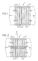
- part of an elongate blank 1 made of a metal has a regular series of long slots 2 which extend across the width of the blank, stopping short of the marginal edges 3 of the blank. Each slot extends across approximately 90% of the width of the blank.
- the material between the long slots 2 can be viewed as the "legs" 7 of the blank.
- a regular series of short slots 4 which extend inwardly of each marginal edge and are positioned centrally between the axes 5 of adjacent pairs of long slots.
- the short slots and the long slots have a very slight overlap and the short slots extend from the marginal edge 3 into the blank by about 5% of the width of the blank.
- the elongate blank extends in the direction of the arrows 6 with the same repeating pattern.
- each leg 7 is provided with a short transverse slot 8 to enhance flexibility.
- a "S"-shaped sealing strip 10 is shown.
- the strip comprises a first U-shaped channel 11 and a second, inversely disposed, glass run channel 12.
- a metallic core 13 provides rigidity to the strip structure.
- the metallic armature may be of the type shown in Figure 1 or 2 which is relatively easy to bend without using expensive "stretch bend" and "contouring" equipment.
- Short projections 15 extend from the opposite wall of the first U-shaped channel 11 from which the elongate limb 14 extends.
- the glass-run channel is provided with two limbs 16 and 17 which abut a pane of glass to seal the glass-run channel 12. Surfaces of the glass-run channel which are to abut glass are covered with a flocking material.
Landscapes
- Engineering & Computer Science (AREA)
- Mechanical Engineering (AREA)
- Seal Device For Vehicle (AREA)
Applications Claiming Priority (2)
| Application Number | Priority Date | Filing Date | Title |
|---|---|---|---|
| GB8629968A GB2199066B (en) | 1986-12-16 | 1986-12-16 | A strip structure. |
| GB8629968 | 1986-12-16 |
Publications (1)
| Publication Number | Publication Date |
|---|---|
| EP0277425A1 true EP0277425A1 (fr) | 1988-08-10 |
Family
ID=10609055
Family Applications (1)
| Application Number | Title | Priority Date | Filing Date |
|---|---|---|---|
| EP87310962A Withdrawn EP0277425A1 (fr) | 1986-12-16 | 1987-12-14 | Armature allongée |
Country Status (2)
| Country | Link |
|---|---|
| EP (1) | EP0277425A1 (fr) |
| GB (1) | GB2199066B (fr) |
Cited By (10)
| Publication number | Priority date | Publication date | Assignee | Title |
|---|---|---|---|---|
| EP0361660A2 (fr) * | 1988-09-29 | 1990-04-04 | Gospel Resource Limited | Article en tôle |
| FR2641719A1 (fr) * | 1989-01-19 | 1990-07-20 | Mesnel Sa Ets | Procede de fabrication d'une armature metallique pour profiles en une matiere synthetique resiliente |
| FR2650517A2 (fr) * | 1989-01-19 | 1991-02-08 | Mesnel Sa Ets | Procede de fabrication d'une armature metallique pour profiles en une matiere synthetique resiliente |
| EP0456561A1 (fr) * | 1990-05-10 | 1991-11-13 | Hutchinson | Armature pour profilé utilisable, en particulier, dans l'industrie automobile |
| EP0508199A1 (fr) * | 1991-03-30 | 1992-10-14 | ERNST SORST + Co. Ges. für Blechverarbeitung mbH | Procédé et dispositif pour la fabrication continue d'un feuillard en forme de métal déployé |
| EP0540183A1 (fr) * | 1991-10-30 | 1993-05-05 | Standard Products Limited | Profil d'étanchéité |
| EP0710788A1 (fr) * | 1994-11-07 | 1996-05-08 | Standard Products Industriel | Armature interne pour joints d'étanchéité |
| GB2345936A (en) * | 1999-01-19 | 2000-07-26 | Draftex Ind Ltd | Reinforcing carrier |
| ES2264322A1 (es) * | 2004-05-10 | 2006-12-16 | Jae Ingenieria Y Desarrollos, S.L. | Mejoras introducidas en armaduras metalicas para juntas de estanqueidad. |
| FR3066951A1 (fr) * | 2017-06-05 | 2018-12-07 | Sealynx International | Profile, notamment pour vehicule automobile, avec un insert lamine. |
Citations (5)
| Publication number | Priority date | Publication date | Assignee | Title |
|---|---|---|---|---|
| US2290842A (en) * | 1939-12-01 | 1942-07-21 | Gen Tire & Rubber Co | Window channeling |
| FR1435921A (fr) * | 1965-03-03 | 1966-04-22 | J O P | Bande de garnissage à profil en forme de u |
| JPS5774245A (en) * | 1980-10-28 | 1982-05-10 | Tokai Kogyo Kk | Reinforcing material for sealed body |
| GB2140065A (en) * | 1983-05-19 | 1984-11-21 | Mesnel Sa Ets | A sealing strip for a retractible window |
| EP0241264A2 (fr) * | 1986-04-07 | 1987-10-14 | Bridgestone Australia Ltd., | Profilé de guidage pour vitres coulissantes |
Family Cites Families (3)
| Publication number | Priority date | Publication date | Assignee | Title |
|---|---|---|---|---|
| US3165793A (en) * | 1961-06-05 | 1965-01-19 | Republic Ind Corp | Flange-gripping flexible sealingstrip carrier |
| GB2115042B (en) * | 1982-01-25 | 1985-05-30 | Draftex Dev Ag | Channel-shaped strips |
| GB8519015D0 (en) * | 1985-07-27 | 1985-09-04 | Draftex Ind Ltd | Channel-shaped strip structures reinforcements |
-
1986
- 1986-12-16 GB GB8629968A patent/GB2199066B/en not_active Expired - Lifetime
-
1987
- 1987-12-14 EP EP87310962A patent/EP0277425A1/fr not_active Withdrawn
Patent Citations (5)
| Publication number | Priority date | Publication date | Assignee | Title |
|---|---|---|---|---|
| US2290842A (en) * | 1939-12-01 | 1942-07-21 | Gen Tire & Rubber Co | Window channeling |
| FR1435921A (fr) * | 1965-03-03 | 1966-04-22 | J O P | Bande de garnissage à profil en forme de u |
| JPS5774245A (en) * | 1980-10-28 | 1982-05-10 | Tokai Kogyo Kk | Reinforcing material for sealed body |
| GB2140065A (en) * | 1983-05-19 | 1984-11-21 | Mesnel Sa Ets | A sealing strip for a retractible window |
| EP0241264A2 (fr) * | 1986-04-07 | 1987-10-14 | Bridgestone Australia Ltd., | Profilé de guidage pour vitres coulissantes |
Non-Patent Citations (1)
| Title |
|---|
| PATENT ABSTRACTS OF JAPAN, vol. 6, no. 157 (M-150)[1035], 18th August 1982; & JP-A-57 074 245 (TOUKAI KOGYO K.K.) 10-05-1982 * |
Cited By (15)
| Publication number | Priority date | Publication date | Assignee | Title |
|---|---|---|---|---|
| EP0361660A2 (fr) * | 1988-09-29 | 1990-04-04 | Gospel Resource Limited | Article en tôle |
| EP0361660A3 (fr) * | 1988-09-29 | 1990-12-27 | Gospel Resource Limited | Article en tôle |
| FR2641719A1 (fr) * | 1989-01-19 | 1990-07-20 | Mesnel Sa Ets | Procede de fabrication d'une armature metallique pour profiles en une matiere synthetique resiliente |
| FR2650517A2 (fr) * | 1989-01-19 | 1991-02-08 | Mesnel Sa Ets | Procede de fabrication d'une armature metallique pour profiles en une matiere synthetique resiliente |
| EP0443278A1 (fr) * | 1989-01-19 | 1991-08-28 | Etablissements Mesnel Societe Anonyme Dite : | Procédé de fabrication d'une armature métallique pour profilés en une matière synthétique résiliente |
| FR2661972A1 (fr) * | 1990-05-10 | 1991-11-15 | Hutchinson | Armature pour profile utilisable, en particulier, dans l'industrie automobile. |
| EP0456561A1 (fr) * | 1990-05-10 | 1991-11-13 | Hutchinson | Armature pour profilé utilisable, en particulier, dans l'industrie automobile |
| EP0508199A1 (fr) * | 1991-03-30 | 1992-10-14 | ERNST SORST + Co. Ges. für Blechverarbeitung mbH | Procédé et dispositif pour la fabrication continue d'un feuillard en forme de métal déployé |
| EP0540183A1 (fr) * | 1991-10-30 | 1993-05-05 | Standard Products Limited | Profil d'étanchéité |
| EP0710788A1 (fr) * | 1994-11-07 | 1996-05-08 | Standard Products Industriel | Armature interne pour joints d'étanchéité |
| FR2726624A1 (fr) * | 1994-11-07 | 1996-05-10 | Standard Products Ind | Armature interne pour joints d'etancheite |
| GB2345936A (en) * | 1999-01-19 | 2000-07-26 | Draftex Ind Ltd | Reinforcing carrier |
| GB2345936B (en) * | 1999-01-19 | 2003-07-02 | Draftex Ind Ltd | Reinforcements or carriers for flexible channel-shaped strips |
| ES2264322A1 (es) * | 2004-05-10 | 2006-12-16 | Jae Ingenieria Y Desarrollos, S.L. | Mejoras introducidas en armaduras metalicas para juntas de estanqueidad. |
| FR3066951A1 (fr) * | 2017-06-05 | 2018-12-07 | Sealynx International | Profile, notamment pour vehicule automobile, avec un insert lamine. |
Also Published As
| Publication number | Publication date |
|---|---|
| GB2199066A (en) | 1988-06-29 |
| GB8629968D0 (en) | 1987-01-28 |
| GB2199066B (en) | 1991-05-15 |
Similar Documents
| Publication | Publication Date | Title |
|---|---|---|
| US4271634A (en) | Channel-shaped sealing strips | |
| US4304816A (en) | Channel-shaped strip structures | |
| US5752345A (en) | Reinforcement for sealing, guiding and trimming strips | |
| US4542610A (en) | Finishing or sealing strips | |
| EP0448270A1 (fr) | Bande d'étanchéité pour un canal de guidage d'une glace coulissante | |
| EP0277425A1 (fr) | Armature allongée | |
| US5194312A (en) | Profiled sealing strip with two reinforcing bands | |
| US4099765A (en) | Channel-shaped guiding, sealing and finishing strips | |
| US3993819A (en) | Channel-shaped sealing, finishing and guide strips and methods of making them | |
| US4348443A (en) | Resilient strip and metal carrier therefor | |
| US4835031A (en) | Profiled strip with smooth reinforcing insert and method of its manufacture | |
| US6079160A (en) | Core metal insert with stagger and offset backbone | |
| US4074465A (en) | Flexible channel-shaped sealing and guiding strips | |
| US4745665A (en) | Elongated clips having a metal core and metal core for such clips | |
| US4678696A (en) | Weather strip | |
| EP0049409A1 (fr) | Barres conductrices d'étanchéité en forme de gouttière | |
| US3455018A (en) | Method of making sealing strip | |
| EP0252659B1 (fr) | Structure de renforcement pour profilé d'étanchéité | |
| EP0305088A2 (fr) | Armature pour structure en bande | |
| US4782549A (en) | Device for connecting a wiping element to the superstructure of a wiper blade | |
| EP0246008B1 (fr) | Bande d'étanchéité | |
| EP0473283B1 (fr) | Renforcements pour bandes flexibles | |
| GB2178468A (en) | Sealing strip | |
| EP0307304A2 (fr) | Elément d'étanchéité pour fenêtres lisses | |
| GB2127884A (en) | Sealing strips |
Legal Events
| Date | Code | Title | Description |
|---|---|---|---|
| PUAI | Public reference made under article 153(3) epc to a published international application that has entered the european phase |
Free format text: ORIGINAL CODE: 0009012 |
|
| AK | Designated contracting states |
Kind code of ref document: A1 Designated state(s): BE DE ES FR IT NL SE |
|
| STAA | Information on the status of an ep patent application or granted ep patent |
Free format text: STATUS: THE APPLICATION IS DEEMED TO BE WITHDRAWN |
|
| 18D | Application deemed to be withdrawn |
Effective date: 19890211 |
|
| RIN1 | Information on inventor provided before grant (corrected) |
Inventor name: PIKE, HAROLD WILLIAM EDWARD |