EP0277086A1 - Method and apparatus for handling small-diameter tubes - Google Patents
Method and apparatus for handling small-diameter tubes Download PDFInfo
- Publication number
- EP0277086A1 EP0277086A1 EP88730004A EP88730004A EP0277086A1 EP 0277086 A1 EP0277086 A1 EP 0277086A1 EP 88730004 A EP88730004 A EP 88730004A EP 88730004 A EP88730004 A EP 88730004A EP 0277086 A1 EP0277086 A1 EP 0277086A1
- Authority
- EP
- European Patent Office
- Prior art keywords
- pipes
- pipe
- mat
- tube
- caliber
- Prior art date
- Legal status (The legal status is an assumption and is not a legal conclusion. Google has not performed a legal analysis and makes no representation as to the accuracy of the status listed.)
- Granted
Links
Images
Classifications
-
- B—PERFORMING OPERATIONS; TRANSPORTING
- B65—CONVEYING; PACKING; STORING; HANDLING THIN OR FILAMENTARY MATERIAL
- B65G—TRANSPORT OR STORAGE DEVICES, e.g. CONVEYORS FOR LOADING OR TIPPING, SHOP CONVEYOR SYSTEMS OR PNEUMATIC TUBE CONVEYORS
- B65G35/00—Mechanical conveyors not otherwise provided for
- B65G35/04—Mechanical conveyors not otherwise provided for comprising a flexible load carrier, e.g. a belt, which is wound up at one end and paid out at the other
-
- B—PERFORMING OPERATIONS; TRANSPORTING
- B23—MACHINE TOOLS; METAL-WORKING NOT OTHERWISE PROVIDED FOR
- B23Q—DETAILS, COMPONENTS, OR ACCESSORIES FOR MACHINE TOOLS, e.g. ARRANGEMENTS FOR COPYING OR CONTROLLING; MACHINE TOOLS IN GENERAL CHARACTERISED BY THE CONSTRUCTION OF PARTICULAR DETAILS OR COMPONENTS; COMBINATIONS OR ASSOCIATIONS OF METAL-WORKING MACHINES, NOT DIRECTED TO A PARTICULAR RESULT
- B23Q7/00—Arrangements for handling work specially combined with or arranged in, or specially adapted for use in connection with, machine tools, e.g. for conveying, loading, positioning, discharging, sorting
- B23Q7/001—Lateral transport of long workpieces
-
- B—PERFORMING OPERATIONS; TRANSPORTING
- B23—MACHINE TOOLS; METAL-WORKING NOT OTHERWISE PROVIDED FOR
- B23Q—DETAILS, COMPONENTS, OR ACCESSORIES FOR MACHINE TOOLS, e.g. ARRANGEMENTS FOR COPYING OR CONTROLLING; MACHINE TOOLS IN GENERAL CHARACTERISED BY THE CONSTRUCTION OF PARTICULAR DETAILS OR COMPONENTS; COMBINATIONS OR ASSOCIATIONS OF METAL-WORKING MACHINES, NOT DIRECTED TO A PARTICULAR RESULT
- B23Q7/00—Arrangements for handling work specially combined with or arranged in, or specially adapted for use in connection with, machine tools, e.g. for conveying, loading, positioning, discharging, sorting
- B23Q7/14—Arrangements for handling work specially combined with or arranged in, or specially adapted for use in connection with, machine tools, e.g. for conveying, loading, positioning, discharging, sorting co-ordinated in production lines
- B23Q7/1426—Arrangements for handling work specially combined with or arranged in, or specially adapted for use in connection with, machine tools, e.g. for conveying, loading, positioning, discharging, sorting co-ordinated in production lines with work holders not rigidly fixed to the transport devices
-
- B—PERFORMING OPERATIONS; TRANSPORTING
- B23—MACHINE TOOLS; METAL-WORKING NOT OTHERWISE PROVIDED FOR
- B23Q—DETAILS, COMPONENTS, OR ACCESSORIES FOR MACHINE TOOLS, e.g. ARRANGEMENTS FOR COPYING OR CONTROLLING; MACHINE TOOLS IN GENERAL CHARACTERISED BY THE CONSTRUCTION OF PARTICULAR DETAILS OR COMPONENTS; COMBINATIONS OR ASSOCIATIONS OF METAL-WORKING MACHINES, NOT DIRECTED TO A PARTICULAR RESULT
- B23Q7/00—Arrangements for handling work specially combined with or arranged in, or specially adapted for use in connection with, machine tools, e.g. for conveying, loading, positioning, discharging, sorting
- B23Q7/16—Loading work on to conveyors; Arranging work on conveyors, e.g. varying spacing between individual workpieces
-
- Y—GENERAL TAGGING OF NEW TECHNOLOGICAL DEVELOPMENTS; GENERAL TAGGING OF CROSS-SECTIONAL TECHNOLOGIES SPANNING OVER SEVERAL SECTIONS OF THE IPC; TECHNICAL SUBJECTS COVERED BY FORMER USPC CROSS-REFERENCE ART COLLECTIONS [XRACs] AND DIGESTS
- Y10—TECHNICAL SUBJECTS COVERED BY FORMER USPC
- Y10T—TECHNICAL SUBJECTS COVERED BY FORMER US CLASSIFICATION
- Y10T29/00—Metal working
- Y10T29/49—Method of mechanical manufacture
- Y10T29/49815—Disassembling
- Y10T29/49821—Disassembling by altering or destroying work part or connector
-
- Y—GENERAL TAGGING OF NEW TECHNOLOGICAL DEVELOPMENTS; GENERAL TAGGING OF CROSS-SECTIONAL TECHNOLOGIES SPANNING OVER SEVERAL SECTIONS OF THE IPC; TECHNICAL SUBJECTS COVERED BY FORMER USPC CROSS-REFERENCE ART COLLECTIONS [XRACs] AND DIGESTS
- Y10—TECHNICAL SUBJECTS COVERED BY FORMER USPC
- Y10T—TECHNICAL SUBJECTS COVERED BY FORMER US CLASSIFICATION
- Y10T29/00—Metal working
- Y10T29/49—Method of mechanical manufacture
- Y10T29/49826—Assembling or joining
- Y10T29/4984—Retaining clearance for motion between assembled parts
-
- Y—GENERAL TAGGING OF NEW TECHNOLOGICAL DEVELOPMENTS; GENERAL TAGGING OF CROSS-SECTIONAL TECHNOLOGIES SPANNING OVER SEVERAL SECTIONS OF THE IPC; TECHNICAL SUBJECTS COVERED BY FORMER USPC CROSS-REFERENCE ART COLLECTIONS [XRACs] AND DIGESTS
- Y10—TECHNICAL SUBJECTS COVERED BY FORMER USPC
- Y10T—TECHNICAL SUBJECTS COVERED BY FORMER US CLASSIFICATION
- Y10T29/00—Metal working
- Y10T29/49—Method of mechanical manufacture
- Y10T29/49826—Assembling or joining
- Y10T29/49863—Assembling or joining with prestressing of part
- Y10T29/4987—Elastic joining of parts
-
- Y—GENERAL TAGGING OF NEW TECHNOLOGICAL DEVELOPMENTS; GENERAL TAGGING OF CROSS-SECTIONAL TECHNOLOGIES SPANNING OVER SEVERAL SECTIONS OF THE IPC; TECHNICAL SUBJECTS COVERED BY FORMER USPC CROSS-REFERENCE ART COLLECTIONS [XRACs] AND DIGESTS
- Y10—TECHNICAL SUBJECTS COVERED BY FORMER USPC
- Y10T—TECHNICAL SUBJECTS COVERED BY FORMER US CLASSIFICATION
- Y10T29/00—Metal working
- Y10T29/49—Method of mechanical manufacture
- Y10T29/49826—Assembling or joining
- Y10T29/49863—Assembling or joining with prestressing of part
- Y10T29/49876—Assembling or joining with prestressing of part by snap fit
-
- Y—GENERAL TAGGING OF NEW TECHNOLOGICAL DEVELOPMENTS; GENERAL TAGGING OF CROSS-SECTIONAL TECHNOLOGIES SPANNING OVER SEVERAL SECTIONS OF THE IPC; TECHNICAL SUBJECTS COVERED BY FORMER USPC CROSS-REFERENCE ART COLLECTIONS [XRACs] AND DIGESTS
- Y10—TECHNICAL SUBJECTS COVERED BY FORMER USPC
- Y10T—TECHNICAL SUBJECTS COVERED BY FORMER US CLASSIFICATION
- Y10T29/00—Metal working
- Y10T29/51—Plural diverse manufacturing apparatus including means for metal shaping or assembling
- Y10T29/5199—Work on tubes
-
- Y—GENERAL TAGGING OF NEW TECHNOLOGICAL DEVELOPMENTS; GENERAL TAGGING OF CROSS-SECTIONAL TECHNOLOGIES SPANNING OVER SEVERAL SECTIONS OF THE IPC; TECHNICAL SUBJECTS COVERED BY FORMER USPC CROSS-REFERENCE ART COLLECTIONS [XRACs] AND DIGESTS
- Y10—TECHNICAL SUBJECTS COVERED BY FORMER USPC
- Y10T—TECHNICAL SUBJECTS COVERED BY FORMER US CLASSIFICATION
- Y10T29/00—Metal working
- Y10T29/53—Means to assemble or disassemble
- Y10T29/53478—Means to assemble or disassemble with magazine supply
-
- Y—GENERAL TAGGING OF NEW TECHNOLOGICAL DEVELOPMENTS; GENERAL TAGGING OF CROSS-SECTIONAL TECHNOLOGIES SPANNING OVER SEVERAL SECTIONS OF THE IPC; TECHNICAL SUBJECTS COVERED BY FORMER USPC CROSS-REFERENCE ART COLLECTIONS [XRACs] AND DIGESTS
- Y10—TECHNICAL SUBJECTS COVERED BY FORMER USPC
- Y10T—TECHNICAL SUBJECTS COVERED BY FORMER US CLASSIFICATION
- Y10T29/00—Metal working
- Y10T29/53—Means to assemble or disassemble
- Y10T29/53657—Means to assemble or disassemble to apply or remove a resilient article [e.g., tube, sleeve, etc.]
-
- Y—GENERAL TAGGING OF NEW TECHNOLOGICAL DEVELOPMENTS; GENERAL TAGGING OF CROSS-SECTIONAL TECHNOLOGIES SPANNING OVER SEVERAL SECTIONS OF THE IPC; TECHNICAL SUBJECTS COVERED BY FORMER USPC CROSS-REFERENCE ART COLLECTIONS [XRACs] AND DIGESTS
- Y10—TECHNICAL SUBJECTS COVERED BY FORMER USPC
- Y10T—TECHNICAL SUBJECTS COVERED BY FORMER US CLASSIFICATION
- Y10T29/00—Metal working
- Y10T29/53—Means to assemble or disassemble
- Y10T29/5367—Coupling to conduit
Definitions
- the invention relates to a method and a device for manipulating small-caliber pipes, in particular pipes with thickenings (such as pipe connection nuts) located at the ends or to be applied, in which bundles of pipes are conveyed transversely, and also relates to production devices and a treatment device. especially for brake, fuel or hydraulic lines.
- thickenings such as pipe connection nuts
- Brake, fuel and hydraulic lines have usually been treated in individual pieces for many years in successive, but spatially separate devices and then delivered in bundles of 40 to 100 pieces to the consumer or brought for further processing. It is disadvantageous that within production (e.g. in boxes and on shelves) or during transport, damage and undesired layers, i.e. Space losses occur. The damage to the surface affects the particularly complex applied corrosion protection layers. Even straight or pre-bent lines can be deformed.
- the invention is therefore based on the object, because of the non-uniform end diameters during manufacture and during transport, to rule out damage to the pipes inside and outside and between two plants, and at the same time to propose handling which is more advantageous for production and transport.
- the object is achieved according to a first proposal in that the tubes are separated axially parallel to a fixed distance continuously on a moving base and then each tube during the continuous movement perpendicular to the tube axis with the neighboring or with a distant tube in a parallel axis position articulated, releasable connections, each corresponding to the specified distance, is provided and that the pipe mat consisting of the pipes and the articulated connections is continuously removed.
- This pipe mat keeps the individual pipes at a distance during production and during transport, thus avoiding damage and at the same time avoiding having to pick up, position and put down the individual pipes several times.
- the device for carrying out the method is designed in such a way that a receptacle for at least one bundle of loose tubes is provided, that a separating device with separating elements set to fixed spacing intervals is connected perpendicular to the longitudinal axis of the bundle, that at least one feed device and one over the separated pipes Push-in device for a large number of releasable joint members to form a tube mat are arranged.
- a separating device with separating elements set to fixed spacing intervals is connected perpendicular to the longitudinal axis of the bundle, that at least one feed device and one over the separated pipes
- Push-in device for a large number of releasable joint members to form a tube mat are arranged.
- Such a device can be loaded automatically and works automatically itself, so that tube mats of any length can be produced.
- the articulated links can also be used without restriction and can therefore always be fed to the pipe mat device.
- the invention further allows the use of a tube mat formed from individual small-caliber tubes with or without tube screw connections and by means of articulated members, which is wound into a coherent bundle, for the transport to further processing facilities.
- Such tubular mat winding coils can be advantageous for transport and for further processing, wherein the means of transport and further processing can be matched to corresponding tubular mat winding bundle diameters or vice versa.
- Damage and transport problems are further avoided by, according to a further solution, along one of straight tube pieces which are articulated in the transverse direction and form a tube mat with the articulated members, which is guided in a stretched position in a production line, facing the tube ends in a manufacturing station Multiples of the spacing of at least one full pitch of successive pipes are arranged and that the pipe mat can be moved in steps of the dividing sections.
- This manufacturing facility also increases the production capacity of such products.
- manufacturing stations for chamfering the pipe ends and / or for deburring the pipe ends and / or for pushing on pipe connection nuts and / or for flanging and / or for brushing the pipe ends and / or for testing the pipes are provided.
- the essential treatment processes are recorded, in order to achieve an at least partially finished one To manufacture conduit that can still be processed into pipe mats or winding coils.
- a production station for unwinding the pipe mat from a collar and a push-off device for removing the joint members in the vertical direction is provided.
- Another alternative to the invention which relocates the production of the pipes closer to the assembly on the motor vehicle, is created in that for brake, fuel or hydraulic lines transported in bundles or pipe mats, then to a separating device and then to an area for production stations for the Phase-in and / or for deburring and / or for pushing on pipe connection nuts and / or for flanging and / or for brushing and / or for testing the pipes an indentation device is provided for connecting the individual pipes by means of articulated members and at the end a drivable winding drum or a layer laying station for pipe mats is arranged on the production line.
- the articulated members form brackets made of lightweight materials, which, according to the manufacturing pitch of the individual pipes, have jaw pairs for the outer pipe caliber have, which are interconnected by means of a thin, elastic web.
- brackets made of light materials which have pairs of jaws for the outer tube caliber corresponding to a transport pitch of the individual tubes, which are connected to one another by means of an approximately trapezoidal, thin, elastic web are connected.
- small-caliber pipes which are often made of steel with several corrosion-inhibiting protective layers, or are made of plastics depending on the intended use (e.g. as fuel, brake or hydraulic lines) depends on the length, the bends and connecting means provided, which provide pipe end processing, for example, thickening of the pipe end may also be required. Accordingly, such pipe sections (or pipes 1 for short) are unwieldy and difficult to transport. Here, transport within a plant between production stations or outside a plant between distant plants is to be understood.
- the tubes 1 are placed in bundles 2 in a receptacle 3 and from there fed via a magazine feed 4 to a separating device 5, which brings the tubes 1 into a fixed spacing 6.
- a magazine wheel 7 is used here as the separating device 5, which in each case provides separating elements 8 in the form of a trough for a tube 1 at the same spacing intervals 6.
- Chain pairs with chain wheels could also serve as the separation device, which would receive the tubes 1 as separation elements 8 by means of holders arranged at a distance from the chain joints.
- the tubes 1 move successively perpendicular to the tube axis 1a, i.e. in the transverse direction 9 on a continuously moving base 10 and pass at equal pitches 6 through a production line which can have any devices for treating the pipe ends 1b.
- a feed device 11 for individual joint members 12 and a push-in device 13 are provided.
- the articulated members 12 form brackets 12a made of light materials, such as plastic or aluminum alloys, which, according to the spacing 6 of the individual tubes 1, have spaced-apart pairs of jaws 12b and 12c, which are matched to the outer tube caliber 14, whereby the design results in a spring force with its effect the tubes 1 can be gripped sufficiently firmly, but also make it possible to release the articulated members 12.
- the articulated members 12, with the pairs of clamping jaws 12b and 12c either comprise adjacent tubes 1 or more distant ones; the choice of the length of a web 15 is therefore determined by X times the pitch 6.
- the supply of the articulated members 12 takes place via reciprocating movements of a magazine slide 16 in the Directions 17a and 17b against a stop 18.
- FIG. 2 shows a one-sided fork shape 18. With progressive movement in the transverse direction 9, a tube mat 19 is thus generated, which can be removed continuously.
- This tube mat 19 can now contain finished, semi-finished or even cut straight tubes 1.
- the tube mat 19 can accordingly be understood as preparation for transport between two production lines, as advantageous preparation for further production steps or as preparation for transport between distant plants.
- a form of transport of the tube mat 19 consists of a wound collar 20 (FIG. 3).
- the collar 20 or the flat stretched tube mat 19 can be treated accordingly in a production facility (FIG. 2).
- a production line 21 is indicated for this purpose. Facing the pipe ends 1b, there are production stations 22 and 23 which process the pipe ends 1b in any form.
- the tube mat 19 is moved at intervals of the spacing 6, so that each tube end 1b reaches each manufacturing station 22 or 23.
- the pipe end 1b can be deburred, chamfered, prepared for sliding on pipe connection nuts 26; the pipe end 1b can also be flanged, brushed or checked.
- a special manufacturing station can be provided for bending the tubes 1.
- a production station for unwinding the tube mat 19 from the collar 20 can also be provided at the beginning of such a production line 21.
- the tubes 1 can be treated individually by setting up a production station as a push-off device 24 for the vertical removal of the articulated members 12, which itself is collected again and the later use to form new pipe mats 19 are supplied.
- the production line 21 can also be designed (Fig. 1 to 3) that subsequent to a separating device 5 and then to an area for the manufacturing stations 22, 23 for chamfering, deburring, pushing on pipe connection nuts, for flanging, brushing or testing a press-in device 13 is provided for reconnecting the individual pipes 1 by means of articulated members 12, so that at the end of the production line 21 the pipe mat 19 can be wound again into a bundle 20 by means of a winding drum 25.
- the winding and unwinding of the tube mat 19 is only dependent on the design of the finished tube 1, whereby it can generally be assumed that a tube delivered in tube mats 19, which forms coil bundles 20, can only be unrolled, after which the fittings, with appropriate preparation of the Pipe ends 1b are to be used and then the pipes 1 are individually finished in a bending station.
- the hinge members 12 are adapted for all possible applications.
- the tubes 1 are located within a tube mat 19 at the production division distance 6. This distance is determined on the one hand by the distance from production stations 22, 23 in the production line 21 and on the other hand by the tube connection nuts 26 or by protective caps 27 that are usually present.
- the joint members 12 are then determined by the shape of the bracket 12a as a whole or by pairs of clamping jaws 12b, 12c together with the web 12d.
- joint action is advantageously achieved by resiliently expandable clamping jaws 12b and 12c, which have a somewhat expanded half-shell shape, so that the outer caliber 14 of a tube 1 comprises a little more than 180 degrees on the circumference becomes.
- the design of the approximately trapezoidal, thin, elastic web 12 (made of thermoplastic plastics) is different in the sense of the mentioned transport pitch 6 a.
- the formation of the web 12d, i.e. the trapezoidal height depends on the conditions of a tube mat 19, which is determined in layers by a layer laying station for reception in rectangular containers. In such cases, the tube mat 19 is layered in a reciprocating manner.
Landscapes
- Engineering & Computer Science (AREA)
- Mechanical Engineering (AREA)
- Rigid Pipes And Flexible Pipes (AREA)
- Storage Of Web-Like Or Filamentary Materials (AREA)
- Grinding Of Cylindrical And Plane Surfaces (AREA)
- Management, Administration, Business Operations System, And Electronic Commerce (AREA)
- Sampling And Sample Adjustment (AREA)
- Devices And Processes Conducted In The Presence Of Fluids And Solid Particles (AREA)
- Heat Treatment Of Articles (AREA)
- Basic Packing Technique (AREA)
Abstract
Description
Die Erfindung betrifft ein Verfahren und eine Einrichtung zum Manipulieren von kleinkalibrigen Rohren, insbesondere von Rohren mit jeweils an den Enden befindlichen bzw. aufzubringenden Verdickungen (wie z.B. Rohrverbindungsmuttern), bei dem Bündel von Rohren quer angefördert werden, und betrifft außerdem Fertigungseinrichtungen und eine Behandlungseinrichtung, insbesondere für Brems-, Kraftstoff- oder Hydraulikleitungen.The invention relates to a method and a device for manipulating small-caliber pipes, in particular pipes with thickenings (such as pipe connection nuts) located at the ends or to be applied, in which bundles of pipes are conveyed transversely, and also relates to production devices and a treatment device. especially for brake, fuel or hydraulic lines.
Brems-, Kraftstoff- und Hydraulikleitungen werden üblicherweise in Einzelstücken seit vielen Jahren in aufeinanderfolgenden, örtlich jedoch getrennten Vorrichtungen weiterbehandelt und anschließend in Bunden von 40 bis 100 Stück an den Verbraucher geliefert bzw. zur Weiterverarbeitung gebracht. Nachteilig dabei ist es, daß innerhalb der Fertigung (z.B. in Kisten und auf Ablagen) oder beim Transport, Beschädigungen und unerwünschte Lagen, d.h. Raumverluste auftreten. Die Beschädigungen an der Oberfläche wirken sich auf die besonders aufwendig aufgebrachten Korrosionsschutzschichten aus. Es können sogar Verformungen der geraden oder schon vorgebogenen Leitungen auftreten.Brake, fuel and hydraulic lines have usually been treated in individual pieces for many years in successive, but spatially separate devices and then delivered in bundles of 40 to 100 pieces to the consumer or brought for further processing. It is disadvantageous that within production (e.g. in boxes and on shelves) or during transport, damage and undesired layers, i.e. Space losses occur. The damage to the surface affects the particularly complex applied corrosion protection layers. Even straight or pre-bent lines can be deformed.
Da solche Leitungsbündel als ganze Bunde schwer zu handhaben sind, treten diese Beschädigungen auch schon vor dem Versand auf. Die Leitungsbündel müssen aber beim Empfänger auch wieder in Einzelstücke aufgelöst werden. Die meisten dieser Schwierigkeiten entstehen deshalb, weil die Leitungen an ihren Enden mit Verdickungen versehen sind, die zum einen aus Schutzkappen für das vorbearbeitete Rohrende (entgrateter Locheingang, entgrateter Außendurchmesser) bestehen und zum anderen aus bereits aufgebrachten Verdickungen, wie z.B. den Rohrverbindungsmuttern oder diesen zugeordneten Bördelrändern. Die Brems-, Kraftstoff- und Hydraulikleitungen sind daher in der Regel an den Enden nicht im Durchmesser einheitlich.Since such bundles are difficult to handle as a whole bundle, this damage occurs even before shipping. However, the line bundles must also be broken down into individual pieces at the receiver. Most of these difficulties arise because the ends of the lines are provided with thickenings, which on the one hand consist of protective caps for the pre-machined pipe end (deburred hole entrance, deburred outer diameter) and, on the other hand, consist of already applied thickenings, such as the pipe connection nuts or flanged edges assigned to them. The brake, fuel and hydraulic lines are therefore usually not uniform in diameter at the ends.
Der Erfindung liegt daher die Aufgabe zugrunde, wegen der uneinheitlichen Enden-Durchmesser während der Fertigung und während des Transports innerhalb und außerhalb sowie zwischen zwei Werken Beschädigungen der Rohre auszuschließen und gleichzeitig eine für die Fertigung und den Transport vorteilhaftere Handhabung vorzuschlagen.The invention is therefore based on the object, because of the non-uniform end diameters during manufacture and during transport, to rule out damage to the pipes inside and outside and between two plants, and at the same time to propose handling which is more advantageous for production and transport.
Die gestellte Aufgabe wird nach einem ersten Vorschlag dadurch gelöst, daß die Rohre achsparallel auf einen festen Abstand kontinuierlich auf einer wandernden Unterlage vereinzelt werden und danach jedes Rohr während der senkrecht zur Rohrachse stattfindenden kontinuierlichen Bewegung mit dem benachbarten oder mit einem entferntern Rohr in paralleler Achslage mit gelenkigen, lösbaren Verbindungen, die jeweils dem festgelegten Abstand entsprechen, versehen wird und daß die aus den Rohren und den gelenkigen Verbindungen bestehende Rohrmatte kontinuierlich abgezogen wird. Diese Rohrmatte hält die Einzelrohre während der Fertigung und während des Transports auf Abstand und vermeidet somit Beschädigungen und erspart gleichzeitig ein mehrfaches Aufnehmen, in Positionbringen und Wiederablegen der einzelnen Rohre.The object is achieved according to a first proposal in that the tubes are separated axially parallel to a fixed distance continuously on a moving base and then each tube during the continuous movement perpendicular to the tube axis with the neighboring or with a distant tube in a parallel axis position articulated, releasable connections, each corresponding to the specified distance, is provided and that the pipe mat consisting of the pipes and the articulated connections is continuously removed. This pipe mat keeps the individual pipes at a distance during production and during transport, thus avoiding damage and at the same time avoiding having to pick up, position and put down the individual pipes several times.
Die Einrichtung zur Durchführung des Verfahrens ist dahingehend ausgestaltet, daß eine Aufnahme für zumindest ein Bündel aus losen Rohren vorgesehen ist, daß sich senkrecht zur Längsachse des Bündels eine Vereinzelungsvorrichtung mit auf feste Teilungsabstände eingestellten Vereinzelungselementen anschließt, daß über den vereinzelten Rohren zumindest eine Zuführvorrichtung und eine Eindrückvorrichtung für eine Vielzahl von wieder lösbaren Gelenkgliedern zur Bildung einer Rohrmatte angeordnet sind. Eine solche Einrichtung kann automatisch beschickt werden und arbeitet selbst automatisiert, so daß beliebig lange Rohrmatten erzeugt werden können. Die Gelenkglieder sind außerdem unbeschränkt verwendbar und können daher immer wieder der Rohrmatten-Einrichtung zugeführt werden.The device for carrying out the method is designed in such a way that a receptacle for at least one bundle of loose tubes is provided, that a separating device with separating elements set to fixed spacing intervals is connected perpendicular to the longitudinal axis of the bundle, that at least one feed device and one over the separated pipes Push-in device for a large number of releasable joint members to form a tube mat are arranged. Such a device can be loaded automatically and works automatically itself, so that tube mats of any length can be produced. The articulated links can also be used without restriction and can therefore always be fed to the pipe mat device.
Die Erfindung gestattet ferner die Anwendung einer aus einzelnen kleinkalibrigen Rohren mit oder ohen Rohrverschraubungen und mittels Gelenkgliedern gebildeten Rohrmatte, die zu einem zusammenhängenden Bund aufgewickelt ist, für den Transport zu Weiterverarbeitungseinrichtungen. Solche Rohrmatten-Wickelbunde können für den Transport und für eine Weiterverarbeitung vorteilhaft sein, wobei das Transportmittel und die Weiterverarbeitung auf entsprechende Rohrmatten-Wickelbund-Durchmesser oder ungekehrt abgestimmt werden können.The invention further allows the use of a tube mat formed from individual small-caliber tubes with or without tube screw connections and by means of articulated members, which is wound into a coherent bundle, for the transport to further processing facilities. Such tubular mat winding coils can be advantageous for transport and for further processing, wherein the means of transport and further processing can be matched to corresponding tubular mat winding bundle diameters or vice versa.
Beschädigungen und Transportprobleme werden ferner dadurch vermieden, indem nach einem weiteren Lösungsvorschlag längs einer aus geraden Rohrstücken, die in Querrichtung gelenkig miteinander verbunden sind und mit den Gelenkgliedern eine Rohrmatte bilden, die in gestreckter Lage in einer Fertigungslinie geführt ist, den Rohrenden zugewendet Fertigungsstationen in einem Vielfachen von Teilungsabständen von zumindest einem vollen Teilungsabstand aufeinanderfolgender Rohre angeordnet sind und daß die Rohrmatte in Schritten der Teilungsabschnitte taktweise bewegbar ist. Diese Fertigungseinrichtung erhöht zusätzlich die Erzeugungsleistung an derartigen Produkten.Damage and transport problems are further avoided by, according to a further solution, along one of straight tube pieces which are articulated in the transverse direction and form a tube mat with the articulated members, which is guided in a stretched position in a production line, facing the tube ends in a manufacturing station Multiples of the spacing of at least one full pitch of successive pipes are arranged and that the pipe mat can be moved in steps of the dividing sections. This manufacturing facility also increases the production capacity of such products.
In Ausgestaltung dieser Lehre wird vorgeschlagen, daß Fertigungsstationen für ein Anphasen der Rohrenden und/oder für ein Entgraten der Rohrenden und/oder für ein Aufschieben von Rohrverbindungsmuttern und/oder für ein Anbördeln und/oder für ein Bürsten der Rohrenden und/oder für ein Prüfen der Rohre vorgesehen sind. Damit werden die wesentlichen Behandlungsvorgänge erfaßt, um ein zumindest teilweise fertiges Leitungsrohr herzustellen, das noch zu Rohrmatten bzw. Wickelbunden verarbeitet werden kann.In an embodiment of this teaching, it is proposed that manufacturing stations for chamfering the pipe ends and / or for deburring the pipe ends and / or for pushing on pipe connection nuts and / or for flanging and / or for brushing the pipe ends and / or for testing the pipes are provided. In this way, the essential treatment processes are recorded, in order to achieve an at least partially finished one To manufacture conduit that can still be processed into pipe mats or winding coils.
Weiterhin wird für diese Erfindungsalternative vorgeschlagen, daß eine Fertigungsstation für das Biegen der vereinzelten Rohre vorgesehen ist. Das Biegen wird im wesentlichen als letzter Arbeitsgang vor der Montage des Leitungsrohres am Kraftfahrzeug eingesetzt.Furthermore, it is proposed for this alternative of the invention that a manufacturing station is provided for bending the individual tubes. Bending is used essentially as the last step before the installation of the conduit on the motor vehicle.
Für eine durchgehende Fertigung der Rohre bis zu Montagereife in einem Automobil ist noch vorteilhaft, daß eine Fertigungsstation für das Abwickeln der Rohrmatte von einem Bund und eine Abdrückvorrichtung für das Entfernen der Gelenkglieder in vertikaler Richtung vorgesehen ist.For continuous production of the pipes until they are ready for assembly in an automobile, it is also advantageous that a production station for unwinding the pipe mat from a collar and a push-off device for removing the joint members in the vertical direction is provided.
Eine weitere Erfindungsalternative, die die Fertigung der Rohre mehr in die Nähe der Montage am Kraftfahrzeug verlegt, wird dadurch geschaffen, daß für in Bunden oder Rohrmatten antransportierten Brems-, Kraftstoff- oder Hydraulikleitungen anschließend an eine Vereinzelungsvorrichtung und anschließend an einen Bereich für Fertigungsstationen für das Anphasen und/oder für das Entgraten und/oder für das Aufschieben von Rohrverbindungsmuttern und/oder für das Anbördeln und/oder für das Bürsten und/oder für das Prüfen der Rohre eine Eindrückvorrichtung für das Verbinden der einzelnen Rohre mittels Gelenkgliedern vorgesehen ist und am Ende der Fertigungslinie eine antreibbare Wickeltrommel oder eine Schichtlegestation für Rohrmatten angeordnet ist.Another alternative to the invention, which relocates the production of the pipes closer to the assembly on the motor vehicle, is created in that for brake, fuel or hydraulic lines transported in bundles or pipe mats, then to a separating device and then to an area for production stations for the Phase-in and / or for deburring and / or for pushing on pipe connection nuts and / or for flanging and / or for brushing and / or for testing the pipes an indentation device is provided for connecting the individual pipes by means of articulated members and at the end a drivable winding drum or a layer laying station for pipe mats is arranged on the production line.
Je nachdem, ob die Rohre noch in der Fertigung benötigt werden oder ob sie schon einer Montage zugeführt werden, wird für die erste Phase vorgeschlagen, daß die Gelenkglieder aus Leichtwerkstoffen hergestellte Bügel bilden, die entsprechend dem Fertigungs-Teilungsabstand der vereinzelten Rohre Klemmbackenpaare für das Rohraußenkaliber aufweisen, die mittels eines dünnen, elastischen Steges miteinander verbunden sind.Depending on whether the pipes are still needed in production or whether they are already being assembled, it is proposed for the first phase that the articulated members form brackets made of lightweight materials, which, according to the manufacturing pitch of the individual pipes, have jaw pairs for the outer pipe caliber have, which are interconnected by means of a thin, elastic web.
Demgegenüber ergeben sich für den Transport, d.h. für eine raumgerechte Verwendung in Rohrmatten-Schichten oder für Rohrmatten-Wickelbunde Vorteile, indem die Gelenkglieder aus Leichtwerkstoffen hergestellte Bügel bilden, die entsprechend einem Transport-Teilungsabstand der vereinzelten Rohre Klemmbackenpaare für das Rohraußenkaliber aufweisen, die mittels eines etwa trapezförmigen, dünnen, elastischen Steges miteinander verbunden sind.In contrast, for transport, i.e. For space-appropriate use in tube mat layers or for tube mat winding coils, advantages by the articulated members forming brackets made of light materials, which have pairs of jaws for the outer tube caliber corresponding to a transport pitch of the individual tubes, which are connected to one another by means of an approximately trapezoidal, thin, elastic web are connected.
Ausführungsbeispiele der Erfindung sind in der Zeichnung schematisch dargestellt und werden nachfolgend erläutert. Es zeigen:
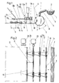
- Fig. 1 eine Seitenansicht der Einrichtung zum Manipulieren von kleinkalibrigen Rohren,
- Fig. 2 die in der Einrichtung gemäß Fig. 1 gebildete Rohrmatte von oben gesehen, mit Fertigungsstationen einer Fertigungslinie und
- Fig. 3 einen gewickelten Rohrmattenbund von der Seite gesehen
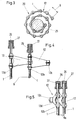
- Fig. 4 eine Draufsicht auf den Ausschnitt einer Rohrmatte, in der die Rohre mit einem Fertigungs-Teilungsabstand angeordnet sind und
- Fig. 5 eine Draufsicht auf die Rohrmatte, wie Fig. 4, jedoch mit einem Transport-Teilungsabstand.
- 1 is a side view of the device for manipulating small-caliber pipes,
- Fig. 2 seen the tube mat formed in the device of FIG. 1 from above, with manufacturing stations of a production line and
- Fig. 3 seen a wound tube mat bundle from the side
- Fig. 4 is a plan view of the section of a tube mat, in which the tubes are arranged with a manufacturing pitch and
- Fig. 5 is a plan view of the tube mat, like Fig. 4, but with a transport pitch.
Das Manipulieren von kleinkalibrigen Rohren, die oft aus Stahl mit mehreren die Korrosion hemmenden Schutzschichten bestehen, oder je nach Verwendungszweck (z.B. als Kraftstoff-, Brems- oder Hydraulikleitungen) aus Kunststoffen hergestellt sind, hängt von der Länge, den vorgesehenen Biegungen und Anschlußmitteln ab, die eine Rohrenden-Bearbeitung vorsehen, wobei z.B. auch Verdickungen des Rohrendes erforderlich werden. Dementsprechend sind derartige Rohrstücke (bzw. kurz Rohre 1 genannt) unhandlich und schwierig zu transportieren. Hierbei ist der Transport innerhalb eines Werkes zwischen Fertigungsstationen oder außerhalb eines Werkes zwischen entferntliegenden Werken zu verstehen.The manipulation of small-caliber pipes, which are often made of steel with several corrosion-inhibiting protective layers, or are made of plastics depending on the intended use (e.g. as fuel, brake or hydraulic lines) depends on the length, the bends and connecting means provided, which provide pipe end processing, for example, thickening of the pipe end may also be required. Accordingly, such pipe sections (or
Die Rohre 1 werden in Bündeln 2 in eine Aufnahme 3 gelegt und von dort aus über eine Magazinzuführung 4 einer Vereinzelungsvorrichtung 5 zugeleitet, die die Rohre 1 in einen festen Teilungsabstand 6 bringt. Als Vereinzelungsvorrichtung 5 dient hier ein Magazinrad 7, das in den gleichen Teilungsabständen 6 jeweils Vereinzelungselemente 8 in Form einer Mulde für ein Rohr 1 vorsieht. Als Vereinzelungsvorrichtung könnten auch (nicht gezeigte) Kettenpaare mit Kettenrädern dienen, die die Rohre 1 mittels im Abstand der Kettengelenke angeordneten Halter als Vereinzelungselemente 8 aufnehmen würden.The
Die Rohre 1 wandern aufeinanderfolgend senkrecht zur Rohrachse 1a, d.h. in Querrichtung 9 auf einer kontinuierlich bewegten Unterlage 10 und gelangen in gleichen Teilungsabständen 6 durch eine Fertigungsstraße, die beliebige Einrichtungen zum Behandeln der Rohrenden 1b aufweisen kann.The
Zunächst sind im Ausführungsbeispiel der Fig. 1 eine Zuführvorrichtung 11 für einzelne Gelenkglieder 12 sowie eine Eindrückvorrichtung 13 vorgesehen. Die Gelenkglieder 12 bilden aus Leichtwerkstoffen, wie Kunststoff oder Aluminiumlegierungen hergestellte Bügel 12a, die entsprechend dem Teilungsabstand 6 der vereinzelten Rohre 1 beabstandete Klemmbackenpaare 12b und 12c besitzen, die auf das Rohraußenkaliber 14 abgestimmt sind, wobei durch die Ausbildung eine Federkraft entsteht, mit deren Wirkung die Rohre 1 ausreichend fest umfaßt werden können, jedoch auch ein Lösen der Gelenkglieder 12 möglich machen. Die Gelenkglieder 12 umfassen mit den Klemmbackenpaaren 12b und 12c entweder benachbarte Rohre 1 oder entferntere; die Wahl der Länge eines Steges 15 wird daher durch das Xfache des Teilungsabstandes 6 bestimmt. Die Zufuhr der Gelenkglieder 12 erfolgt über hin- und hergehende Bewegungen eines Magazinschiebers 16 in den Richtungen 17a and 17b gegen einen Anschlag 18.First of all, in the exemplary embodiment in FIG. 1, a
Die Ausbildung der Klemmbackenpaare 12a, 12b ergibt sich außerdem aus Fig. 2, die eine einseitige Gabelform 18 zeigt. Bei fortschreitender Bewegung in Querrichtung 9 wird damit eine Rohrmatte 19 erzeugt, die kontinuierlich abgezogen werden kann.The formation of the
Diese Rohrmatte 19 kann nunmehr fertige, halbfertige oder auch nur abgelängte, gerade Rohre 1 enthalten. Die Rohrmatte 19 kann demgemäß als Vorbereitung für einen Transport zwischen zwei Fertigungslinien, als vorteilhafte Vorbereitung für weitere Fertigungsschritte oder als Vorbereitung für den Transport zwischen entferntliegenden Werken verstanden werden. Eine Transportform der Rohrmatte 19 besteht in einem gewickelten Bund 20 (Fig. 3).
Der Bund 20 oder auch die flach ausgestreckte Rohrmatte 19 können in einer Fertigungseinrichtung (Fig. 2) entsprechend behandelt werden. Hierzu ist eine Fertigungslinie 21 angedeutet. Den Rohrenden 1b zugewendet, befinden sich Fertigungsstationen 22 und 23, die die Rohrenden 1b in irgendeiner Form bearbeiten. Die Rohrmatte 19 wird taktweise in Entfernungen der Teilungsabstände 6 bewegt, so daß jedes Rohrende 1b vor jede Fertigungsstation 22 oder 23 gelangt. An solchen Fertigungsstationen 22, 23 kann das Rohrende 1b entgratet, angephast, für das Aufschieben von Rohrverbindungsmuttern 26 vorbereitet werden; das Rohrende 1b kann auch angebördelt werden, kann gebürstet oder geprüft werden. Eine besondere Fertigungsstation kann für das Biegen der Rohre 1 vorgesehen sein. Innerhalb einer solchen Fertigungslinie 21 kann auch am Anfang eine Fertigungsstation für das Abwickeln der Rohrmatte 19 von dem Bund 20 vorgesehen sein.This
The
Hierbei können die Rohre 1 einzeln behandelt werden, indem eine Fertigungsstation als Abdrückvorrichtung 24 für das vertikale Entfernen der Gelenkglieder 12 eingerichtet ist, die selbst wieder eingesammelt und der späteren Verwendung zur Bildung neuer Rohrmatten 19 zugeführt werden.Here, the
Die Fertigungslinie 21 kann auch so gestaltet sein (Fig. 1 bis 3), daß anschließend an eine Vereinzelungsvorrichtung 5 und anschließend an eine Bereich für die Fertigungsstationen 22, 23 für das Anphasen, Entgraten, Aufschieben von Rohrverbindungsmuttern, für das Anbördeln, Bürsten oder Prüfen eine Eindrückvorrichtung 13 für das erneute Verbinden der einzelnen Rohre 1 mittels Gelenkgliedern 12 vorgesehen ist, so daß am Ende der Fertigungslinie 21 die Rohrmatte 19 wieder mittels einer Wickeltrommel 25 zu einem Bund 20 gewickelt werden kann. Das Aufwickeln und das Abwickeln der Rohrmatte 19 ist lediglich von der Gestaltung des fertigen Rohres 1 abhängig, wobei im allgemeinen davon auszugehen ist, daß ein in Rohrmatten 19 angeliefertes Rohr, das Wickelbunde 20 bildet, nur abzurollen ist, danach die Fittings bei entsprechender Vorbereitung der Rohrenden 1b einzusetzen sind und danach die Rohre 1 einzeln in einer Biegestation fertiggemacht werden. Es ist jedoch selbstverständlich möglich, zwischen den einzelnen Fertigungslinien der unterschiedlichsten Art die Rohre 1 jeweils wieder zu Rohrmatten 19 zusammenzusetzen und diese anschließend entweder flach der weiteren Verarbeitung zuzuführen oder auf Wickelbunde 20 zu geben.The
Für alle Anwendungsmöglichkeiten findet eine Anpassung der Gelenkglieder 12 statt. Gemäß Fig. 4 befinden sich die Rohre 1 innerhalb einer Rohrmatte 19 auf Fertigungs-Teilungsabstand 6. Dieser Abstand wird einerseits durch den Abstand von Fertigungsstationen 22,23 in der Fertigungslinie 21 bestimmt und andererseits durch die Rohrverbindungsmuttern 26 bzw. durch meist vorhandene Schutzkappen 27. Die Gelenkglieder 12 werden danach durch die Form des Bügels 12a insgesamt bzw. durch Klemmbackenpaare 12b,12c zusammen mit dem Steg 12d bestimmt. Hierbei wird vorteilhafterweise Gelenkwirkung durch federnd auspreizbare Klemmbacken 12b und 12c erzielt, die eine etwas erweiterte Halbschalenform aufweisen, so daß das Außenkaliber 14 eines Rohres 1 etwas mehr als 180 Grad am Umfang umfaßt wird. Vorteilhafterweise bilden zwei Klemmbacken 12c auf ein und demselben Rohr 1 zusammen mit nur einem Klemmbacken 12b auf dem benachbarten Rohr 1 einen Bügel 12a, so daß ein Ineinandergreifen von Bügel 12a zu Bügel 12a stattfindet. Dadurch wird erheblich an Raum eingespart.The
Die Anordnung der Bügel 12a gemäß Fig. 5 erfolgt weitestgehend wie zu Fig. 4 beschrieben. Unterschiedlich ist im Sinn des erwähnten Transport-Teilungsabstandes 6a die Gestaltung des etwa trapezförmigen, dünnen, elastischen (aus thermplastischen Kunststoffen hergestellten) Steges 12d. Die Ausbildung des Steges 12d, d.h. die Trapezhöhe richtet sich nach den Gegebenheiten einer Rohrmatte 19, wobei eine solche in Schichten durch eine Schichtlegestation zur Aufnahme in rechteckigen Behältern bestimmt wird. Die Rohrmatte 19 wird in solchen Fällen in hin- und hergehendem Verlauf geschichtet.5 is largely arranged as described for FIG. 4. The design of the approximately trapezoidal, thin, elastic web 12 (made of thermoplastic plastics) is different in the sense of the mentioned transport pitch 6 a. The formation of the
Claims (10)
dadurch gekennzeichnet,
daß die Rohre achsparallel auf einen festen Abstand kontinuierlich auf einer wandernden Unterlage vereinzelt werden und danach jedes Rohr während der senkrecht zur Rohrachse stattfindenden kontinuierlichen Bewegung mit dem benachbarten oder mit einem entfernteren Rohr in paralleler Achslage mit gelenkigen, lösbaren Verbindungen, die jeweils dem festgelegten Abstand entsprechen, versehen wird und daß die aus den Rohren und den gelenkigen Verbindungen bestehende Rohrmatte kontinuierlich abgezogen wird.1. Method for manipulating small-caliber pipes, in particular pipes with thickenings located at the ends or to be applied, in which bundles of pipes are conveyed transversely,
characterized,
that the pipes are separated axially parallel to a fixed distance continuously on a moving base and then each pipe during the continuous movement perpendicular to the pipe axis with the neighboring or with a more distant pipe in a parallel axial position with articulated, detachable connections, each corresponding to the specified distance , is provided and that the pipe mat consisting of the pipes and the articulated connections is continuously withdrawn.
dadurch gekennzeichnet,
daß eine Aufnahme (3) für zumindest ein Bündel (2) aus losen Rohren (1) vorgesehen ist, daß sich senkrecht zur Längsachse (1a) des Bündels (2) eine Vereinzelungsvorrichtung (5) mit auf feste Teilungsabstände (6) eingestellten Vereinzelungselementen (80 anschließt, daß über den vereinzelten Rohren (1) zumindest eine Zuführvorrichtung (11) und eine Eindrückvorrichtung (13) für eine Vielzahl von wieder lösbaren Gelenkgliedern (12) zur Bildung einer Rohrmatte (19) angeordnet sind.2. Device for manipulating small-caliber pipes, in particular pipes with thickenings located at the ends or to be applied,
characterized,
that a receptacle (3) for at least one bundle (2) of loose tubes (1) is provided, that a separating device (5) with separating elements (6) set to fixed spacing distances (6) is perpendicular to the longitudinal axis (1a) of the bundle (2) 80 connects that at least one feed device (11) and one press-in device (13) for a multiplicity of detachable joint members (12) are arranged above the individual pipes (1) to form a pipe mat (19).
daß längs einer aus geraden Rohrstücken (1), die in Querrichtung (9) gelenkig miteinander verbunden sind und mit den Gelenkgliedern (12) eine Rohrmatte (19) bilden, die in gestreckter Lage in einer Fertigungslinie (21) geführt ist, den Rohrenden (1b) zugewendet Fertigungsstationen (22,23) in einem Vielfachen von Teilungsabständen (6) von zumindest einem vollen Teilungsabstand (6) aufeinanderfolgender Rohre (1) angeordnet sind und daß die Rohrmatte (19) in Schritten der Teilungsabschnitte (6) taktweise bewegbar ist.4. Manufacturing device for small-caliber pipes, in particular for brake, fuel or hydraulic lines in motor vehicles, characterized in that
that along one of straight pipe sections (1) which are articulated in the transverse direction (9) and form with the joint members (12) a pipe mat (19) which is guided in a stretched position in a production line (21), the pipe ends ( 1b) facing production stations (22, 23) are arranged in a multiple of pitch intervals (6) of at least one full pitch spacing (6) of successive tubes (1) and that the tube mat (19) can be moved in steps in the pitch portions (6).
dadurch gekennzeichnet,
daß Fertigungsstationen (22,23) für ein Anphasen der Rohrenden (1b) und/oder für ein Entgraten der Rohrenden (1b) und/oder für ein Aufschieben von Rohrverbindungsmuttern und/oder für ein Anbördeln und/oder für ein Bürsten der Rohrenden (1b) und/oder für ein Prüfen der Rohre (1) vorgesehen sind.5. Manufacturing device according to claim 4,
characterized,
that manufacturing stations (22, 23) for chamfering the pipe ends (1b) and / or for deburring the pipe ends (1b) and / or for pushing on pipe connection nuts and / or for flanging and / or for brushing the pipe ends (1b ) and / or for testing the pipes (1) are provided.
dadurch gekennzeichnet,
daß eine Fertigungsstation (22,23) für das Biegen der vereinzelten Rohre (1) vorgesehen ist.6. Manufacturing device according to claim 4,
characterized,
that a manufacturing station (22, 23) is provided for bending the individual tubes (1).
dadurch gekennzeichnet,
daß eine Fertigungsstation (22,23) für das Abwickeln der Rohrmatte (19) von einem Bund (20) und eine Abdrückvorrichtung (24) für das Entfernen der Gelenkglieder (12) in vertikaler Richtung vorgesehen ist.7. Manufacturing device according to one or more of claims 4 to 6,
characterized,
that a manufacturing station (22, 23) for unwinding the tube mat (19) from a collar (20) and a push-off device (24) for removing the articulated members (12) is provided in the vertical direction.
daß für in Bunden (20) oder Rohrmatten (19) antransportierten Brems-, Kraftstoff- oder Hydraulikleitungen anschließend an eine Vereinzelungsvorrichtung (5) und anschließend an einen Bereich für Fertigungsstationen (22,23) für das Anphasen und/oder für das Entgraten und/oder für das Aufschieben von Rohrverbindungsmuttern und/oder für das Anbördeln und/oder für das Bürsten und/oder für das Prüfen der Rohre (1) eine Eindrückvorrichtung (13) für das Verbinden der einzelnen Rohre (1) mittels Gelenkgliedern (12) vorgesehen ist und am Ende der Fertigungslinie (21) eine antreibbare Wickeltrommel (25) oder eine Schichtlegestation für Rohrmatten (19) angeordnet ist.8. Treatment device for small-caliber pipes, in particular for brake, fuel or hydraulic lines in motor vehicles, characterized in that
that for brake, fuel or hydraulic lines transported in bundles (20) or pipe mats (19), then to a separating device (5) and then to an area for production stations (22, 23) for chamfering and / or for deburring and / or for pushing on pipe connection nuts and / or for flanging and / or for brushing and / or for testing the pipes (1) an indentation device (13) for the Connecting the individual pipes (1) by means of articulated members (12) is provided and at the end of the production line (21) a drivable winding drum (25) or a layer laying station for pipe mats (19) is arranged.
daß die Gelenkglieder (12) aus Leichtwerkstoffen hergestellte Bügel (12a) bilden, die entsprechend dem Fertigungs-Teilungsabstand (6) der vereinzelten Rohre (1) Klemmbackenpaare (12b,12c) für das Rohraußenkaliber (14) aufweisen, die mittels eines dünnen, elastischen Steges (12d) miteinander verbunden sind.9. Device according to one or more of claims 1 to 8, characterized in
that the articulated members (12) form brackets (12a) made of light materials, which according to the manufacturing pitch (6) of the individual tubes (1) have pairs of jaws (12b, 12c) for the outer tube caliber (14), which are by means of a thin, elastic Web (12d) are interconnected.
daß die Gelenkglieder (12) aus Leichtwerkstoffen hergestellte Bügel (12a) bilden, die entsprechend einem Transport-Teilungsabstand (6a) der vereinzelten Rohre (1) Klemmbackenpaare (12b,12c) für das Rohraußenkaliber (14) aufweisen, die mittels eines etwa trapezförmigen, dünnen, elastischen Stegs (12d) miteinander verbunden sind.10. Device according to one or more of claims 1 to 8, characterized in
that the articulated members (12) form brackets (12a) made of lightweight materials, which have pairs of clamping jaws (12b, 12c) for the outer tube caliber (14) according to a transport pitch (6a) of the individual tubes (1), which are formed by means of an approximately trapezoidal, thin, elastic web (12d) are interconnected.
Priority Applications (1)
| Application Number | Priority Date | Filing Date | Title |
|---|---|---|---|
| AT88730004T ATE62465T1 (en) | 1987-01-21 | 1988-01-07 | METHOD AND EQUIPMENT FOR MANIPULATING SMALL-CALIBRE PIPE. |
Applications Claiming Priority (2)
| Application Number | Priority Date | Filing Date | Title |
|---|---|---|---|
| DE3701556 | 1987-01-21 | ||
| DE3701556A DE3701556C1 (en) | 1987-01-21 | 1987-01-21 | Method and device for manipulating small-caliber pipes as well as manufacturing devices and a treatment device, in particular for brake, fuel or hydraulic lines |
Publications (2)
| Publication Number | Publication Date |
|---|---|
| EP0277086A1 true EP0277086A1 (en) | 1988-08-03 |
| EP0277086B1 EP0277086B1 (en) | 1991-04-10 |
Family
ID=6319167
Family Applications (1)
| Application Number | Title | Priority Date | Filing Date |
|---|---|---|---|
| EP88730004A Expired - Lifetime EP0277086B1 (en) | 1987-01-21 | 1988-01-07 | Method and apparatus for handling small-diameter tubes |
Country Status (7)
| Country | Link |
|---|---|
| US (1) | US4907326A (en) |
| EP (1) | EP0277086B1 (en) |
| JP (1) | JPS63218022A (en) |
| AT (1) | ATE62465T1 (en) |
| BR (1) | BR8800181A (en) |
| CA (1) | CA1310990C (en) |
| DE (2) | DE3701556C1 (en) |
Cited By (4)
| Publication number | Priority date | Publication date | Assignee | Title |
|---|---|---|---|---|
| CN105459412A (en) * | 2015-12-19 | 2016-04-06 | 胜利油田新大管业科技发展有限责任公司 | Fiber-wound glass fiber reinforced plastic pipe fitting manufacturing equipment and manufacturing process |
| CN108247351A (en) * | 2018-01-26 | 2018-07-06 | 绍兴永威机械设备有限公司 | Hilted broadsword milling font bottle cap processing unit (plant) |
| CN110802180A (en) * | 2019-11-22 | 2020-02-18 | 重庆理工大学 | Automatic loading and unloading device |
| CN114102149A (en) * | 2021-09-30 | 2022-03-01 | 安吉金标家具厂 | Chair leg preparation machine |
Families Citing this family (20)
| Publication number | Priority date | Publication date | Assignee | Title |
|---|---|---|---|---|
| CN102642645B (en) * | 2012-04-27 | 2014-04-23 | 深圳大学 | Cover sleeving device of automatic tube packer |
| CN102922423A (en) * | 2012-10-30 | 2013-02-13 | 吴江久升纸业有限公司 | Paper tube conveying fixing clamp |
| CN104227485A (en) * | 2014-08-29 | 2014-12-24 | 中核(天津)机械有限公司 | Automatic feeding device for shaft parts |
| CN104308815B (en) * | 2014-09-28 | 2016-04-06 | 上海锅炉厂有限公司 | Bipyramid platform assembling assembly fixture |
| CN104399836A (en) * | 2014-12-01 | 2015-03-11 | 浙江科宇金属材料有限公司 | Conveying mechanism of copper bar straightening machine |
| CN105269070B (en) * | 2015-10-27 | 2018-01-05 | 芜湖市泰能电热器具有限公司 | A kind of blanking device of electrothermal tube |
| CN105290751B (en) * | 2015-11-26 | 2018-02-06 | 东北大学 | The pushing cover device of tubing automatic cover sleeving machine |
| CN105414302B (en) * | 2015-12-01 | 2017-08-01 | 保隆(安徽)汽车配件有限公司 | A kind of High efficient pipe partses forming machine |
| CN105538022B (en) * | 2016-01-29 | 2018-02-02 | 奉化科盛微型轴业有限公司 | Shaft-like work processes autoloader |
| CN107052186B (en) * | 2017-03-24 | 2018-11-16 | 浙江新诚汽车部件有限公司 | A kind of exhaust pipe collecting box |
| CN109261820A (en) * | 2018-08-10 | 2019-01-25 | 慈溪市天泽厨具有限公司 | A kind of feeding device of port machine |
| DE102018221781A1 (en) * | 2018-12-14 | 2020-06-18 | Schott Ag | Vitreous layer, vitreous bundle and manufacturing process of a vitreous layer |
| DE102018221782A1 (en) | 2018-12-14 | 2020-06-18 | Schott Ag | Vitreous layer, vitreous bundle and packing process |
| CN109757841B (en) * | 2018-12-29 | 2021-04-06 | 枞阳县中邦科技信息咨询有限公司 | Extrusion forming device for umbrella rib middle rod |
| CN109731939A (en) * | 2018-12-29 | 2019-05-10 | 枞阳县华丽雨具有限公司 | A kind of extrusion body in molding machine |
| CN109793326B (en) * | 2018-12-29 | 2021-04-02 | 枞阳县中邦科技信息咨询有限公司 | Preparation method of polymer waterproof umbrella |
| CN111283809B (en) * | 2020-02-28 | 2021-08-10 | 张家港市欧微自动化研发有限公司 | Automatic slot hole forming method based on automatic slot hole forming equipment |
| JP2021138453A (en) | 2020-03-02 | 2021-09-16 | ショット アクチエンゲゼルシャフトSchott AG | Bundle of tubular and/or rod-like glass article, method for manufacture thereof, and bundle unpacking method |
| EP3875396A1 (en) | 2020-03-02 | 2021-09-08 | Schott Ag | Bundle of tubular and/or rod shaped glass articles, method for its fabrication as well as for unpacking said bundle |
| CN112894450B (en) * | 2021-02-07 | 2022-05-17 | 安徽省华源塑业科技有限公司 | Automatic feeding device for pipe machining |
Citations (6)
| Publication number | Priority date | Publication date | Assignee | Title |
|---|---|---|---|---|
| DE350609C (en) * | 1920-07-17 | 1922-03-23 | Alfred De Fries | Machine for processing screw bolts with a feeding device designed as a workpiece holder and acting intermittently |
| GB1085734A (en) * | 1965-01-12 | 1967-10-04 | Holding Intercito Sa | Improvements in or relating to apparatus for charging endless conveyor means with rod-like elements |
| FR2277750A1 (en) * | 1974-07-10 | 1976-02-06 | Freville Paul | Device to place cylindrical objects on support - uses rotating drums with edge recesses to remove objects from bulk store |
| US3983986A (en) * | 1973-11-09 | 1976-10-05 | Automatisme Et Technique | Cirulating conveyor |
| AT361848B (en) * | 1976-11-22 | 1981-04-10 | Oxy Metal Industries Corp | CONVEYOR DEVICE FOR CUP, CYLINDRICAL OBJECTS |
| DE3438123A1 (en) * | 1984-10-18 | 1986-04-24 | Lothar 8500 Nürnberg Sachße | Method and device for the storage, transport and feeding to a processing station or the like of industrial components |
Family Cites Families (12)
| Publication number | Priority date | Publication date | Assignee | Title |
|---|---|---|---|---|
| US2803176A (en) * | 1954-01-04 | 1957-08-20 | Marshall E Gazette | Machine for feeding paper tubes and crimping an end thereof |
| DE1241889B (en) * | 1963-01-11 | 1967-06-08 | Licentia Gmbh | Device for holding or fixing the connection ends of a plurality of lines in switchgear or control systems |
| NL135644C (en) * | 1964-02-27 | |||
| US3631973A (en) * | 1968-10-04 | 1972-01-04 | United Nuclear Corp | Convolute ground package of cylindrical objects |
| US3720992A (en) * | 1971-03-01 | 1973-03-20 | J Hyatt | Automatic pipe handling system |
| US3874048A (en) * | 1972-12-04 | 1975-04-01 | Bundy Corp | Method and apparatus for fabricating tubing |
| SE7309849L (en) * | 1973-07-13 | 1975-01-14 | Sunds Ab | BAR CALCULATOR. |
| US4285460A (en) * | 1979-08-13 | 1981-08-25 | Midcon Pipeline Equipment Co. | Method and apparatus for double jointing pipe |
| US4343076A (en) * | 1980-11-17 | 1982-08-10 | Northern Telecom Limited | Apparatus, and a method, for removing terminal pins from a bandolier |
| JPS57102738A (en) * | 1980-12-19 | 1982-06-25 | Nippon Kokan Kk <Nkk> | Adaptive processing apparatus |
| JPS58172106A (en) * | 1982-04-01 | 1983-10-08 | Toyoda Gosei Co Ltd | Carrying equipment of long-sized material |
| JPH0342311Y2 (en) * | 1985-05-23 | 1991-09-04 |
-
1987
- 1987-01-21 DE DE3701556A patent/DE3701556C1/en not_active Expired
-
1988
- 1988-01-07 EP EP88730004A patent/EP0277086B1/en not_active Expired - Lifetime
- 1988-01-07 AT AT88730004T patent/ATE62465T1/en not_active IP Right Cessation
- 1988-01-07 DE DE8888730004T patent/DE3862307D1/en not_active Expired - Fee Related
- 1988-01-18 CA CA000556754A patent/CA1310990C/en not_active Expired - Fee Related
- 1988-01-19 JP JP63009441A patent/JPS63218022A/en active Pending
- 1988-01-20 US US07/146,082 patent/US4907326A/en not_active Expired - Fee Related
- 1988-01-20 BR BR8800181A patent/BR8800181A/en unknown
Patent Citations (6)
| Publication number | Priority date | Publication date | Assignee | Title |
|---|---|---|---|---|
| DE350609C (en) * | 1920-07-17 | 1922-03-23 | Alfred De Fries | Machine for processing screw bolts with a feeding device designed as a workpiece holder and acting intermittently |
| GB1085734A (en) * | 1965-01-12 | 1967-10-04 | Holding Intercito Sa | Improvements in or relating to apparatus for charging endless conveyor means with rod-like elements |
| US3983986A (en) * | 1973-11-09 | 1976-10-05 | Automatisme Et Technique | Cirulating conveyor |
| FR2277750A1 (en) * | 1974-07-10 | 1976-02-06 | Freville Paul | Device to place cylindrical objects on support - uses rotating drums with edge recesses to remove objects from bulk store |
| AT361848B (en) * | 1976-11-22 | 1981-04-10 | Oxy Metal Industries Corp | CONVEYOR DEVICE FOR CUP, CYLINDRICAL OBJECTS |
| DE3438123A1 (en) * | 1984-10-18 | 1986-04-24 | Lothar 8500 Nürnberg Sachße | Method and device for the storage, transport and feeding to a processing station or the like of industrial components |
Cited By (4)
| Publication number | Priority date | Publication date | Assignee | Title |
|---|---|---|---|---|
| CN105459412A (en) * | 2015-12-19 | 2016-04-06 | 胜利油田新大管业科技发展有限责任公司 | Fiber-wound glass fiber reinforced plastic pipe fitting manufacturing equipment and manufacturing process |
| CN108247351A (en) * | 2018-01-26 | 2018-07-06 | 绍兴永威机械设备有限公司 | Hilted broadsword milling font bottle cap processing unit (plant) |
| CN110802180A (en) * | 2019-11-22 | 2020-02-18 | 重庆理工大学 | Automatic loading and unloading device |
| CN114102149A (en) * | 2021-09-30 | 2022-03-01 | 安吉金标家具厂 | Chair leg preparation machine |
Also Published As
| Publication number | Publication date |
|---|---|
| DE3701556C1 (en) | 1988-06-01 |
| JPS63218022A (en) | 1988-09-12 |
| BR8800181A (en) | 1988-08-30 |
| CA1310990C (en) | 1992-12-01 |
| DE3862307D1 (en) | 1991-05-16 |
| EP0277086B1 (en) | 1991-04-10 |
| ATE62465T1 (en) | 1991-04-15 |
| US4907326A (en) | 1990-03-13 |
Similar Documents
| Publication | Publication Date | Title |
|---|---|---|
| EP0277086B1 (en) | Method and apparatus for handling small-diameter tubes | |
| DE2408120A1 (en) | METHOD AND DEVICE FOR CONNECTING TWO TUBE-SHAPED ELEMENTS BY FRICTION WELDING | |
| DE4124715C2 (en) | Device for multiple bending of a metal pipe | |
| DE3322194C2 (en) | ||
| DE2750640C2 (en) | ||
| DE19814091A1 (en) | Device for the production of reinforcement cages for rectangular pipes made of concrete | |
| DE2205971A1 (en) | Process for the production of bent tubes made of rubber or an analogous material | |
| DE2943960A1 (en) | METHOD FOR SHAPING ELBOW AND DEVICE FOR IMPLEMENTING THE METHOD | |
| EP0419524A1 (en) | Method and device for the manufacture of wiring harnesses. | |
| EP2009652B1 (en) | Method of manufacturing transformer cores | |
| EP0368967B1 (en) | Process and installation for producing two-layered welded network bodies | |
| DE2726305A1 (en) | PROCESS FOR BENDING BARS, TUBES, PROFILES ETC. | |
| EP0134223B1 (en) | Method for fabricating thermo insulated compound profiles for windows, doors and fa ades | |
| EP2380676A1 (en) | Method for operating a bending machine with movable straightening unit | |
| DE10304327A1 (en) | Process for bending slim workpieces uses a handling arrangement with six degrees of freedom to load a clamped workpiece with a bending moment at various sections of its longitudinal axis on interaction with a tool | |
| WO1999044783A1 (en) | Method and device for transferring a hollow-profile blank | |
| DE102022117386B4 (en) | Production station for the manufacture of body parts and process for the production | |
| DE4142220A1 (en) | Connector for tubes or bars, for scaffolding or protective railings - consists of two shells with holders and connecting bar, with screw connection to clamp shells | |
| DE102004012297A1 (en) | Pipe bending assembly has a number of pipe-bending stations arranged in series and one or more transfer stations | |
| DE102004015073B3 (en) | Process for bending a workpiece, especially an antiroll bar for a motor vehicle, comprises arranging the workpiece between a bending stock having two curved bending surfaces with one bending curvature and two bending elements | |
| DE102021122587B3 (en) | Device and method for positioning a plurality of conductor pieces for equipping a stator core with conductor pieces | |
| DE4300311C2 (en) | Device for deforming rod-shaped components | |
| DE4242002A1 (en) | System for bending continuously produced material - has central material clamping unit consisting of two independently operable pairs of clamping tools | |
| EP0528132B1 (en) | Device for the production of bellows | |
| EP4009453A1 (en) | Holding device |
Legal Events
| Date | Code | Title | Description |
|---|---|---|---|
| PUAI | Public reference made under article 153(3) epc to a published international application that has entered the european phase |
Free format text: ORIGINAL CODE: 0009012 |
|
| AK | Designated contracting states |
Kind code of ref document: A1 Designated state(s): AT BE DE ES FR GB IT NL SE |
|
| 17P | Request for examination filed |
Effective date: 19880810 |
|
| RAP1 | Party data changed (applicant data changed or rights of an application transferred) |
Owner name: BUNDY GMBH |
|
| 17Q | First examination report despatched |
Effective date: 19900328 |
|
| GRAA | (expected) grant |
Free format text: ORIGINAL CODE: 0009210 |
|
| AK | Designated contracting states |
Kind code of ref document: B1 Designated state(s): AT BE DE ES FR GB IT NL SE |
|
| PG25 | Lapsed in a contracting state [announced via postgrant information from national office to epo] |
Ref country code: IT Free format text: LAPSE BECAUSE OF FAILURE TO SUBMIT A TRANSLATION OF THE DESCRIPTION OR TO PAY THE FEE WITHIN THE PRE;WARNING: LAPSES OF ITALIAN PATENTS WITH EFFECTIVE DATE BEFORE 2007 MAY HAVE OCCURRED AT ANY TIME BEFORE 2007. THE CORRECT EFFECTIVE DATE MAY BE DIFFERENT FROM THE ONE RECORDED.SCRIBED TIME-LIMIT Effective date: 19910410 Ref country code: ES Free format text: THE PATENT HAS BEEN ANNULLED BY A DECISION OF A NATIONAL AUTHORITY Effective date: 19910410 Ref country code: NL Effective date: 19910410 Ref country code: SE Effective date: 19910410 |
|
| REF | Corresponds to: |
Ref document number: 62465 Country of ref document: AT Date of ref document: 19910415 Kind code of ref document: T |
|
| ET | Fr: translation filed | ||
| REF | Corresponds to: |
Ref document number: 3862307 Country of ref document: DE Date of ref document: 19910516 |
|
| GBT | Gb: translation of ep patent filed (gb section 77(6)(a)/1977) | ||
| NLV1 | Nl: lapsed or annulled due to failure to fulfill the requirements of art. 29p and 29m of the patents act | ||
| PGFP | Annual fee paid to national office [announced via postgrant information from national office to epo] |
Ref country code: FR Payment date: 19911212 Year of fee payment: 5 |
|
| PGFP | Annual fee paid to national office [announced via postgrant information from national office to epo] |
Ref country code: GB Payment date: 19911216 Year of fee payment: 5 |
|
| PGFP | Annual fee paid to national office [announced via postgrant information from national office to epo] |
Ref country code: BE Payment date: 19911217 Year of fee payment: 5 |
|
| PGFP | Annual fee paid to national office [announced via postgrant information from national office to epo] |
Ref country code: AT Payment date: 19911223 Year of fee payment: 5 |
|
| PLBE | No opposition filed within time limit |
Free format text: ORIGINAL CODE: 0009261 |
|
| STAA | Information on the status of an ep patent application or granted ep patent |
Free format text: STATUS: NO OPPOSITION FILED WITHIN TIME LIMIT |
|
| 26N | No opposition filed | ||
| PG25 | Lapsed in a contracting state [announced via postgrant information from national office to epo] |
Ref country code: GB Effective date: 19930107 Ref country code: AT Effective date: 19930107 |
|
| PG25 | Lapsed in a contracting state [announced via postgrant information from national office to epo] |
Ref country code: BE Effective date: 19930131 |
|
| BERE | Be: lapsed |
Owner name: BUNDY G.M.B.H. Effective date: 19930131 |
|
| GBPC | Gb: european patent ceased through non-payment of renewal fee |
Effective date: 19930107 |
|
| PGFP | Annual fee paid to national office [announced via postgrant information from national office to epo] |
Ref country code: DE Payment date: 19930928 Year of fee payment: 6 |
|
| PG25 | Lapsed in a contracting state [announced via postgrant information from national office to epo] |
Ref country code: FR Effective date: 19930930 |
|
| REG | Reference to a national code |
Ref country code: FR Ref legal event code: ST |
|
| PG25 | Lapsed in a contracting state [announced via postgrant information from national office to epo] |
Ref country code: DE Effective date: 19941001 |