EP0276926A1 - Klemmschelle - Google Patents
Klemmschelle Download PDFInfo
- Publication number
- EP0276926A1 EP0276926A1 EP88300293A EP88300293A EP0276926A1 EP 0276926 A1 EP0276926 A1 EP 0276926A1 EP 88300293 A EP88300293 A EP 88300293A EP 88300293 A EP88300293 A EP 88300293A EP 0276926 A1 EP0276926 A1 EP 0276926A1
- Authority
- EP
- European Patent Office
- Prior art keywords
- transverse
- end portion
- clip
- portions
- abutment means
- Prior art date
- Legal status (The legal status is an assumption and is not a legal conclusion. Google has not performed a legal analysis and makes no representation as to the accuracy of the status listed.)
- Granted
Links
Images
Classifications
-
- F—MECHANICAL ENGINEERING; LIGHTING; HEATING; WEAPONS; BLASTING
- F16—ENGINEERING ELEMENTS AND UNITS; GENERAL MEASURES FOR PRODUCING AND MAINTAINING EFFECTIVE FUNCTIONING OF MACHINES OR INSTALLATIONS; THERMAL INSULATION IN GENERAL
- F16L—PIPES; JOINTS OR FITTINGS FOR PIPES; SUPPORTS FOR PIPES, CABLES OR PROTECTIVE TUBING; MEANS FOR THERMAL INSULATION IN GENERAL
- F16L3/00—Supports for pipes, cables or protective tubing, e.g. hangers, holders, clamps, cleats, clips, brackets
- F16L3/08—Supports for pipes, cables or protective tubing, e.g. hangers, holders, clamps, cleats, clips, brackets substantially surrounding the pipe, cable or protective tubing
- F16L3/12—Supports for pipes, cables or protective tubing, e.g. hangers, holders, clamps, cleats, clips, brackets substantially surrounding the pipe, cable or protective tubing comprising a member substantially surrounding the pipe, cable or protective tubing
-
- Y—GENERAL TAGGING OF NEW TECHNOLOGICAL DEVELOPMENTS; GENERAL TAGGING OF CROSS-SECTIONAL TECHNOLOGIES SPANNING OVER SEVERAL SECTIONS OF THE IPC; TECHNICAL SUBJECTS COVERED BY FORMER USPC CROSS-REFERENCE ART COLLECTIONS [XRACs] AND DIGESTS
- Y10—TECHNICAL SUBJECTS COVERED BY FORMER USPC
- Y10T—TECHNICAL SUBJECTS COVERED BY FORMER US CLASSIFICATION
- Y10T24/00—Buckles, buttons, clasps, etc.
- Y10T24/14—Bale and package ties, hose clamps
- Y10T24/1498—Plastic band
-
- Y—GENERAL TAGGING OF NEW TECHNOLOGICAL DEVELOPMENTS; GENERAL TAGGING OF CROSS-SECTIONAL TECHNOLOGIES SPANNING OVER SEVERAL SECTIONS OF THE IPC; TECHNICAL SUBJECTS COVERED BY FORMER USPC CROSS-REFERENCE ART COLLECTIONS [XRACs] AND DIGESTS
- Y10—TECHNICAL SUBJECTS COVERED BY FORMER USPC
- Y10T—TECHNICAL SUBJECTS COVERED BY FORMER US CLASSIFICATION
- Y10T24/00—Buckles, buttons, clasps, etc.
- Y10T24/44—Clasp, clip, support-clamp, or required component thereof
- Y10T24/44017—Clasp, clip, support-clamp, or required component thereof with specific mounting means for attaching to rigid or semirigid supporting structure or structure-to-be-secured
- Y10T24/44026—Clasp, clip, support-clamp, or required component thereof with specific mounting means for attaching to rigid or semirigid supporting structure or structure-to-be-secured for cooperating with aperture in supporting structure or structure-to-be-secured
-
- Y—GENERAL TAGGING OF NEW TECHNOLOGICAL DEVELOPMENTS; GENERAL TAGGING OF CROSS-SECTIONAL TECHNOLOGIES SPANNING OVER SEVERAL SECTIONS OF THE IPC; TECHNICAL SUBJECTS COVERED BY FORMER USPC CROSS-REFERENCE ART COLLECTIONS [XRACs] AND DIGESTS
- Y10—TECHNICAL SUBJECTS COVERED BY FORMER USPC
- Y10T—TECHNICAL SUBJECTS COVERED BY FORMER US CLASSIFICATION
- Y10T24/00—Buckles, buttons, clasps, etc.
- Y10T24/44—Clasp, clip, support-clamp, or required component thereof
- Y10T24/44274—Clasp, clip, support-clamp, or required component thereof having either discrete flaccid or thin, nonbiasing, integral, connecting hinge
Definitions
- This invention relates to clips, and more particularly to clips for clipping together a plurality of elongate members or clipping at least one such member to a surface.
- Such clips comprising a gapped annular body, the end portions of which are adapted to interengage to close the body are known.
- US Patent Specification 3913187 discloses such a clip wherein the end portions are interengageable over a range of degrees of overlapped relationship to enable the body to tightly grip the elongate member or members disposed within the body.
- a disadvantage with such clips is that the end portions may become transversely misaligned either during fitting or in service such that they do not interengage properly with a resultant risk that the clip body may inadvertently open.
- a clip comprising a gapped annular body, the end portions of which are adapted to interengage in overlapped relationship to close the body, said end portions being provided with abutment means for preventing transverse relative movement of the end portions when they are so interengaged.
- One of the end portions may be bifurcated such that the forks thereof overlap the other end portion inwardly and outwardly thereof when said end portions are interengaged, and in one embodiment of the invention, to be described hereinafter, said forks comprise first and second transverse portions of said one end portion, said first transverse portion being arranged to overlap a first transverse portion of the other end portion and the second transverse portion being arranged to be overlapped by a second transverse portion of the other end portion when said end portions are interengaged.
- the clip may comprise first abutment means on said other end portion for engaging first abutment means on said first transverse portion of said one end portion for preventing transverse movement of said first transverse portion of said one end portion across the second transverse portion of said other end portion and second abutment means on said other end portion for engaging second abutment means on said second transverse portion of said one end portion for preventing transverse movement of said second transverse portion of said one end portion across the first transverse portion of said other end portion.
- the first transverse portions of said end portions are provided with cooperable ramp teeth for interengaging said end portions over a range of degrees of overlapped relationship.
- the ramp teeth may be spaced from the side edges of said first transverse portions remote from the second transverse portions, and said first abutment means on said other end portion may comprise ends of the ramp teeth thereon.
- first abutment means on said other end portion may comprise a side face of a projection on said other end portion, said first abutment means of said first transverse portion of said one end portion comprising a side edge thereof.
- the first portion of said one end portion has a chamfered free end, with which said projection is cooperable for guiding said first transverse portion of said one end portion into overlapping relationship with said first transverse portion of said other end portion.
- the second abutment means on said other end portion may comprise a side face thereon, said second abutment means of said second transverse portion of said one end portion comprising a side edge thereof.
- This side face may comprise a side face of a recess in the other end portion for receiving the second transverse portion of said one end portion.
- the second transverse portion of said one end portion may have a chamfered free end, with which said side face of said other end portion is cooperable for guiding said second transverse portion of said one end portion into overlapping relationship with said second transverse portion of said other end portion.
- the gapped annular body of the clip may comprise an integral thermoplastics moulding.
- the integral body may comprise two body portions hinged together, and a mounting member may extend from one of the body portions and a hook member may be provided on the other of the body portions.
- the invention also includes a clip comprising a gapped annular body, the end portions of which are adapted to interengage in overlapped relationship to close the body, wherein one of said end portions is bifurcated such that a first transverse portion is arranged to overlap a first transverse portion of the other end portion and a second transverse portion is arranged to be overlapped by a second transverse portion of the other end portion when said end portions are interengaged.
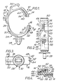
- a clip 10 for an electrical wiring harness of a vehicle which clip is moulded integrally from a thermoplastics material such as acetal.
- the clip comprises a gapped annular body 12, the end portions 14 and 16 of which are adapted to interengage to close the body.
- Figure 1 illustrates the body in an open condition and the interengagement of the end portions is illustrated in Figure 4 which will be described in more detail hereinafter.
- the body is moulded in the illustrated open condition both to facilitate moulding and to ease assembly of the harness into the clip.
- the resilience of the body permits the end portions to be brought into interengagement from the open condition, and in the illustrated embodiment this is assisted by forming the body of a wall 18 which is reinforced with external ribbing 20 over two portions 22,24 of the body which portions are interconnected by an unreinforced section 26 of the wall 18 which serves as a hinge between the two body portions 22,24. Additionally the section 26 of the wall 18 could be reduced in thickness.
- a mounting member 28 extends from the body portion 24 to enable the clip to be snap-fitted into an aperture in a vehicle panel in a manner known per se .
- a hook member 30 is provided on the body portion 22 so that the clip may retain one or more other elongate members in addition to the elctrical wiring harness.
- the end portions 14,16 of the body are adapted to interengage in overlapped relationship.
- one of the end portions 14 is bifurcated such that the forks 32,34 thereof overlap the other end portion 16 inwardly and outwardly thereof when the end portions are interengaged.
- the forks 32,34 comprise first and second transverse portions of the end portion 14, the first transverse portion 32 being arranged to overlap a first transverse portion 36 of the end portion 16 and the second transverse portion 34 being arranged to be overlapped by a second transverse portion 38 of the end portion when the end portions are interengaged.
- the end portions 14 and 16 are provided with abutment means for preventing transverse relative movement of the end portions when they are interengaged in overlapped relationship.
- these abutment means comprise first abutment means on end portion 16 for engaging first abutment means on the transverse portion 32 of end portion 14 for preventing transverse movement of portion 32 across transverse portion 34 of end portion 14, and second abutment means on end portion 16 for engaging second abutment means on the transverse portion 34 of end portion 14 for preventing transverse movement of portion 34 across portion 32.
- the first abutment means on the end portion 16 comprises the ends 48 of the ramp teeth thereon, which abut against a wall 50 on the portion 32 adjacent the corresponding ends of the ramp teeth 40 thereon.
- the first abutment means on the end portion 16 comprises a side face 52 of a projection 54 thereon arranged for engaging a side edge 56 of the portion 32 of end portion 14.
- the side face 52 and side edge 56 are slightly spaced apart to facilitate interengagement of the end portions and to allow for manufacturing tolerances.
- the side face 52 would be engaged by the side edge 56 of portion 14 to prevent the portion 14 moving across portion 38 if the abutment between teeth ends 48 and wall 50 is lost.
- the second abutment means on the end portion 16 referred to above comprises a side face 58 thereon which abuts against a side edge 60 of the transverse portion 34 of end portion 14.
- This side face 58 comprises a side face of a recess 62 in the end portion 16 for receiving the portion 34 of end portion 14.
- transverse end portion 32 of end portion 14 is chamfered as shown at 63 to cooperate with the projection 54 when the end portions 14,16 are being interengaged such that the projection can guide the portion 32 into overlapping relationship with the transverse portion 36 of end portion 16.
- the free end of transverse end portion 34 is chamfered as shown at 64 to cooperate with side face 58 when the end portions 14,16 are being interengaged such that the side face 58 can guide the portion 34 into overlapping relationship with the transverse end portion of end portion 16.
Applications Claiming Priority (2)
| Application Number | Priority Date | Filing Date | Title |
|---|---|---|---|
| GB8702148 | 1987-01-30 | ||
| GB8702148A GB2200398B (en) | 1987-01-30 | 1987-01-30 | Band clips |
Publications (2)
| Publication Number | Publication Date |
|---|---|
| EP0276926A1 true EP0276926A1 (de) | 1988-08-03 |
| EP0276926B1 EP0276926B1 (de) | 1992-09-02 |
Family
ID=10611504
Family Applications (1)
| Application Number | Title | Priority Date | Filing Date |
|---|---|---|---|
| EP88300293A Expired - Lifetime EP0276926B1 (de) | 1987-01-30 | 1988-01-14 | Klemmschelle |
Country Status (5)
| Country | Link |
|---|---|
| US (1) | US4840345A (de) |
| EP (1) | EP0276926B1 (de) |
| DE (1) | DE3874155T2 (de) |
| ES (1) | ES2035258T3 (de) |
| GB (1) | GB2200398B (de) |
Cited By (11)
| Publication number | Priority date | Publication date | Assignee | Title |
|---|---|---|---|---|
| EP0582200A1 (de) * | 1992-08-03 | 1994-02-09 | Panduit Corp. | Drahthalteklammer |
| DE9405364U1 (de) * | 1994-03-31 | 1994-07-28 | Panduit Gmbh | Halteclip |
| EP0650003A1 (de) * | 1993-10-20 | 1995-04-26 | GOBBI, Gianfranco | Universal Klemme zur Halterung von Systemen von freiliegenden Elektro- oder Fernmeldekabeln oder von Rohrleitungen auf einer Wand |
| FR2713440A1 (fr) * | 1993-12-07 | 1995-06-16 | Pilat Gerard | Attache destinée à fixer les cultures en palissade. |
| DE19622175C1 (de) * | 1996-06-01 | 1997-10-16 | Porsche Ag | Halterung für ein Kabelbündel |
| NL1015823C2 (nl) * | 2000-07-27 | 2002-01-29 | Clicquick A G | Haaksluiting en pijpbeugel voorzien van een dergelijke haaksluiting. |
| WO2004001923A1 (de) * | 2002-06-25 | 2003-12-31 | Faurecia Innenraum Systeme Gmbh | Kabelhalterung |
| EP1415863A1 (de) * | 2002-09-30 | 2004-05-06 | Newfrey LLC | Befestigungselement zum Befestigen eines Bodenteppichs und eines Kabelbaums an einer Schwellenabdeckung |
| NL1026050C2 (nl) * | 2004-04-27 | 2005-10-31 | Franciscus Gerardus Ma Keijzer | Plantbindbeugel. |
| EP1783436A2 (de) * | 2005-10-06 | 2007-05-09 | Eurotherm S.P.A. | Befestigungsklammer für Rohre von Fussbodenheizungssystemen |
| EP1925866A1 (de) * | 2006-11-06 | 2008-05-28 | Newfrey LLC | Schelle aus Kunststoff |
Families Citing this family (63)
| Publication number | Priority date | Publication date | Assignee | Title |
|---|---|---|---|---|
| DE3737113C1 (de) * | 1987-11-02 | 1989-03-02 | Raymond A Fa | Halteklammer zur Befestigung von Kabeln oder Kabelbuendeln |
| ES2021890B3 (es) * | 1988-07-18 | 1991-11-16 | Egli Fischer & Co | Abrazadera tubular |
| US4958792A (en) * | 1989-05-09 | 1990-09-25 | B-Line Systems, Inc. | Clip for supporting conduit and the like |
| US5024405A (en) * | 1989-05-12 | 1991-06-18 | Mcguire Robert H | Pipe clamp |
| DE3933304A1 (de) * | 1989-10-05 | 1991-04-18 | United Carr Gmbh Trw | Bandelement zum umschlingen und haltern von gegenstaenden |
| US5065562A (en) * | 1990-01-29 | 1991-11-19 | The Standard Products Company | Sealing and fastening system for greenhouses |
| JP2556979Y2 (ja) * | 1991-03-01 | 1997-12-08 | 株式会社ニフコ | 線、棒状物のクランプ |
| US5349780A (en) * | 1992-07-20 | 1994-09-27 | David E. Dyke | Ribbed plant support poles |
| DE4225742A1 (de) * | 1992-08-04 | 1994-02-10 | United Carr Gmbh Trw | Halteelement |
| US5564672A (en) * | 1994-06-06 | 1996-10-15 | Matson; Bradley A. | Conduit binding system for use in restricted spaces |
| US5590859A (en) * | 1995-01-23 | 1997-01-07 | Lord; Paul J. | Ratcheting pipe hanger assembly |
| IT1278968B1 (it) * | 1995-03-03 | 1997-12-02 | Lys Fusion Spa | Graffa per il fissaggio di tubi conduttori e simili organi |
| US5772258A (en) * | 1995-12-20 | 1998-06-30 | Tyton-Hellermann Corp. | Conduit clamp and tether |
| US5806819A (en) * | 1995-12-22 | 1998-09-15 | Martone; Michael A. | Clip-type fastening device with clamping means securable about a fixed member |
| US5658046A (en) * | 1996-01-16 | 1997-08-19 | Lear Corporation | Vehicle seat trim cover attachment strip |
| US5775653A (en) * | 1996-05-30 | 1998-07-07 | Chrysler Corporation | Clamp device for attaching and positively orienting a vehicular component to a tubular member |
| US5782090A (en) * | 1996-11-27 | 1998-07-21 | Excel Industries, Inc. | Hose clip |
| US6186454B1 (en) * | 1996-12-31 | 2001-02-13 | Dane R. Olsen | Aesthetically-pleasing, post-mounted sign holder |
| US5819374A (en) * | 1997-07-09 | 1998-10-13 | Ellenistic, Llc | Clip fastener for radiant tubing and other thin objects |
| DE19823992A1 (de) * | 1998-05-28 | 1999-12-02 | Ludwig Schnabl | Rastklemmschelle für Kabel- und Mantelleitungen, flexible und starre Rohre |
| USD420569S (en) * | 1998-06-18 | 2000-02-15 | Donald Evans | Attachment clip |
| US6303856B1 (en) | 1998-07-29 | 2001-10-16 | Hendrix Wire & Cable, Inc. | Aerial cable spacer with anti-dislodging cable retainer |
| US6206331B1 (en) | 1998-07-30 | 2001-03-27 | Ewd, L.L.C. | D-shaped wire harness clip with ratchet lock |
| US6164605A (en) * | 1998-11-04 | 2000-12-26 | General Motors Corporation | Brake line captured band clamp |
| US6443402B1 (en) | 2000-12-01 | 2002-09-03 | Commscope Properties, Llc | Cable hanger |
| US6725535B2 (en) | 2002-04-17 | 2004-04-27 | Cliptie Corporation | Clip applicator tool |
| DE602004031110D1 (de) * | 2003-06-13 | 2011-03-03 | Cooper Standard Automotive Inc | Befestigungssystem für einen auf einer unterlage angebrachten schlauch |
| US7207532B1 (en) * | 2003-10-09 | 2007-04-24 | Roberts Jeffrey A | Boom stand |
| KR100527972B1 (ko) * | 2003-10-17 | 2005-11-09 | 현대자동차주식회사 | 자동차 도어 스카프 트림 고정 구조 |
| ITTO20040088A1 (it) * | 2004-02-17 | 2004-05-17 | Itw Automotive Italia S R L | Elemento di ritegno a fascetta per componenti assialsimmetrici quali cavi o tubetti, in particolare per l'applicazione su veicoli |
| EP1987935A3 (de) * | 2004-12-01 | 2008-11-19 | Nitto Denko Corporation | Schaumfüllelement |
| US7178203B2 (en) * | 2005-02-28 | 2007-02-20 | Illinois Tool Works Inc | Anti-removal ratchet clip |
| US8926562B2 (en) * | 2005-12-30 | 2015-01-06 | Hospira, Inc. | Syringe holding system |
| DE102006017878A1 (de) * | 2006-04-13 | 2007-10-25 | Newfrey Llc, Newark | Befestigungsclip |
| GB0723913D0 (en) * | 2007-12-07 | 2008-01-23 | Airbus Uk Ltd | Line routing clip |
| US8091262B2 (en) * | 2008-12-23 | 2012-01-10 | American Gasket Technologies, Inc. | Attachable price tag holder |
| US20100243834A1 (en) * | 2009-03-26 | 2010-09-30 | Pole Pals Llc | Decorative apparatus for an iv pole and method for use of same |
| BRPI1014331A2 (pt) * | 2009-07-07 | 2016-04-05 | Illinois Tool Works | "braçadeira de cabo com autocentralização" |
| CN102686267A (zh) * | 2009-12-31 | 2012-09-19 | 美国圣戈班性能塑料公司 | 用于管道连接器的系统、方法及设备 |
| GB201100622D0 (en) * | 2011-01-14 | 2011-03-02 | Phillips Sean | Article of furniture |
| WO2012122311A1 (en) | 2011-03-07 | 2012-09-13 | Nordson Corporation | Clamp for sanitary fitting |
| US8961340B2 (en) * | 2011-07-28 | 2015-02-24 | Ryan Lee Boatwright | Compression collar apparatus |
| US8398424B1 (en) | 2011-09-02 | 2013-03-19 | Cisco Technology, Inc. | Power cord retainer |
| US20140259620A1 (en) * | 2013-03-13 | 2014-09-18 | Thaddeus R. Hicks | Hose retention system |
| US20150133861A1 (en) | 2013-11-11 | 2015-05-14 | Kevin P. McLennan | Thermal management system and method for medical devices |
| US10143795B2 (en) | 2014-08-18 | 2018-12-04 | Icu Medical, Inc. | Intravenous pole integrated power, control, and communication system and method for an infusion pump |
| DE102014221104A1 (de) * | 2014-10-17 | 2016-04-21 | Robert Bosch Gmbh | Befestigungsvorrichtung für eine Leitung in einem Fahrzeug |
| ES2809505T3 (es) | 2015-05-26 | 2021-03-04 | Icu Medical Inc | Dispositivo de administración de fluido de infusión desechable para la administración programable de fármacos de gran volumen |
| ITUB201553190U1 (it) * | 2015-07-14 | 2017-01-14 | Anna Stiatti | Struttura di supporto di apparecchiature elettroidrauliche per impianti di irrigazione, applicabile a un pozzetto interrabile per l'alloggiamento e la protezione di tali apparecchiature elettroidrauliche. |
| GB201516237D0 (en) * | 2015-09-14 | 2015-10-28 | Ellis Patents Holdings Ltd | A clamp |
| GB2547647B (en) * | 2016-02-23 | 2021-10-06 | Hebe Studio Ltd | Cover for a wire mesh panel |
| US20180094751A1 (en) * | 2016-09-30 | 2018-04-05 | Level 3 Communications, Llc | Elevated cable support structure |
| WO2018067827A1 (en) * | 2016-10-05 | 2018-04-12 | Avery Dennison Corporation | Buddy clip |
| JP6880497B2 (ja) * | 2017-04-19 | 2021-06-02 | 株式会社オンダ製作所 | 長尺体保持具 |
| USD931718S1 (en) * | 2017-06-07 | 2021-09-28 | Illinois Tool Works Inc. | Retainer |
| US10570609B2 (en) * | 2017-10-19 | 2020-02-25 | The Boeing Company | Systems and methods for joining composite panels |
| DE102018101790A1 (de) * | 2018-01-26 | 2019-08-01 | Harting Electric Gmbh & Co. Kg | Dichteinsatz |
| USD889254S1 (en) * | 2018-10-17 | 2020-07-07 | Ramon Ceravalls Pujol | Pipe clamp |
| US11125356B2 (en) * | 2019-06-05 | 2021-09-21 | Unirac Inc. | Conduit mount bracket |
| USD939079S1 (en) | 2019-08-22 | 2021-12-21 | Icu Medical, Inc. | Infusion pump |
| US10797477B1 (en) * | 2019-10-31 | 2020-10-06 | Aptiv Technologies Limited | Clip for flat wiring and robotic assembly |
| US11856347B1 (en) | 2020-01-16 | 2023-12-26 | David M. Roberts | Speaker stand |
| GB2602955B (en) * | 2020-09-22 | 2023-01-11 | Keymed Medical & Industrial Equipment Ltd | Multifunctional equipment holder |
Citations (7)
| Publication number | Priority date | Publication date | Assignee | Title |
|---|---|---|---|---|
| US3942750A (en) * | 1974-08-13 | 1976-03-09 | Thomas & Betts Corporation | Adjustable clamp |
| DE2442414A1 (de) * | 1974-09-05 | 1976-03-18 | Turek Werner | Kabelschelle |
| US4061299A (en) * | 1975-05-06 | 1977-12-06 | Nifco Inc. | Cord clamp |
| DE3139058A1 (de) * | 1981-10-01 | 1983-04-21 | BLOUNTHURST Ltd., Swanage, Dorset | Loesbare klemmschelle zur befestigung einer schlauchleitung od.dgl. |
| US4557024A (en) * | 1984-02-06 | 1985-12-10 | 501 Evelyn Investments Ltd. | Clamp for hose, tubing, or the like |
| DE3544683A1 (de) * | 1985-02-07 | 1986-08-07 | Kitagawa Industries Co. Ltd., Nagoya, Aichi | Kabelhalter |
| US4609171A (en) * | 1983-09-05 | 1986-09-02 | Kitagawa Industries Co., Ltd. | Electric wire bundle clamp |
Family Cites Families (14)
| Publication number | Priority date | Publication date | Assignee | Title |
|---|---|---|---|---|
| GB580186A (en) * | 1944-06-15 | 1946-08-29 | Cheney & Son Ltd C | Improvements in band clips of the kind having closing worm gear |
| GB762456A (en) * | 1951-07-27 | 1956-11-28 | Dalmine Spa | A connecting device for constructing industrial structures such as scaffolding, particularly of the lattice type |
| JPS5064874U (de) * | 1973-10-18 | 1975-06-12 | ||
| GB1567852A (en) * | 1976-03-09 | 1980-05-21 | Nifco Inc | Band clamp |
| US4183120A (en) * | 1978-05-19 | 1980-01-15 | Thorne George W | Encircling devices |
| US4214351A (en) * | 1978-08-15 | 1980-07-29 | Wenk Raymond C | Snap-on clamp |
| DE8013412U1 (de) * | 1980-05-17 | 1980-09-25 | Remih, Harry, Remich (Luxemburg) | Kunststoffschlauchschelle |
| IT8034032V0 (it) * | 1980-07-24 | 1980-07-24 | Zanussi A Spa Industrie | Fascetta stringitubo elastica. |
| DE3126488C2 (de) * | 1981-07-04 | 1983-04-21 | Fa. A. Raymond, 7850 Lörrach | Rohrschelle |
| GB2142376B (en) * | 1983-06-09 | 1987-06-24 | United Carr Ltd Trw | Retaining clip |
| US4623102A (en) * | 1983-12-14 | 1986-11-18 | Apple Adhesives, Inc. | Article clamp |
| US4564163A (en) * | 1984-06-04 | 1986-01-14 | Trw United-Carr Limited | Retaining clip |
| US4663807A (en) * | 1985-04-12 | 1987-05-12 | Bozzo Michael J | Reusable clip |
| US4637097A (en) * | 1985-10-21 | 1987-01-20 | Chrysler Motors Corporation | Cable bundler clip |
-
1987
- 1987-01-30 GB GB8702148A patent/GB2200398B/en not_active Expired - Fee Related
-
1988
- 1988-01-14 ES ES198888300293T patent/ES2035258T3/es not_active Expired - Lifetime
- 1988-01-14 DE DE8888300293T patent/DE3874155T2/de not_active Expired - Fee Related
- 1988-01-14 EP EP88300293A patent/EP0276926B1/de not_active Expired - Lifetime
- 1988-01-29 US US07/149,696 patent/US4840345A/en not_active Expired - Fee Related
Patent Citations (7)
| Publication number | Priority date | Publication date | Assignee | Title |
|---|---|---|---|---|
| US3942750A (en) * | 1974-08-13 | 1976-03-09 | Thomas & Betts Corporation | Adjustable clamp |
| DE2442414A1 (de) * | 1974-09-05 | 1976-03-18 | Turek Werner | Kabelschelle |
| US4061299A (en) * | 1975-05-06 | 1977-12-06 | Nifco Inc. | Cord clamp |
| DE3139058A1 (de) * | 1981-10-01 | 1983-04-21 | BLOUNTHURST Ltd., Swanage, Dorset | Loesbare klemmschelle zur befestigung einer schlauchleitung od.dgl. |
| US4609171A (en) * | 1983-09-05 | 1986-09-02 | Kitagawa Industries Co., Ltd. | Electric wire bundle clamp |
| US4557024A (en) * | 1984-02-06 | 1985-12-10 | 501 Evelyn Investments Ltd. | Clamp for hose, tubing, or the like |
| DE3544683A1 (de) * | 1985-02-07 | 1986-08-07 | Kitagawa Industries Co. Ltd., Nagoya, Aichi | Kabelhalter |
Cited By (16)
| Publication number | Priority date | Publication date | Assignee | Title |
|---|---|---|---|---|
| EP0582200A1 (de) * | 1992-08-03 | 1994-02-09 | Panduit Corp. | Drahthalteklammer |
| EP0650003A1 (de) * | 1993-10-20 | 1995-04-26 | GOBBI, Gianfranco | Universal Klemme zur Halterung von Systemen von freiliegenden Elektro- oder Fernmeldekabeln oder von Rohrleitungen auf einer Wand |
| FR2713440A1 (fr) * | 1993-12-07 | 1995-06-16 | Pilat Gerard | Attache destinée à fixer les cultures en palissade. |
| DE9405364U1 (de) * | 1994-03-31 | 1994-07-28 | Panduit Gmbh | Halteclip |
| DE19622175C1 (de) * | 1996-06-01 | 1997-10-16 | Porsche Ag | Halterung für ein Kabelbündel |
| US6935599B2 (en) | 2000-07-27 | 2005-08-30 | Starquick International Ltd. | Hook closure and pipe clip with such a hook closure |
| NL1015823C2 (nl) * | 2000-07-27 | 2002-01-29 | Clicquick A G | Haaksluiting en pijpbeugel voorzien van een dergelijke haaksluiting. |
| WO2002010629A1 (en) * | 2000-07-27 | 2002-02-07 | Starquick International Ltd | Hook closure and pipe clip with such a hook closure |
| WO2004001923A1 (de) * | 2002-06-25 | 2003-12-31 | Faurecia Innenraum Systeme Gmbh | Kabelhalterung |
| EP1415863A1 (de) * | 2002-09-30 | 2004-05-06 | Newfrey LLC | Befestigungselement zum Befestigen eines Bodenteppichs und eines Kabelbaums an einer Schwellenabdeckung |
| US7140070B2 (en) | 2002-09-30 | 2006-11-28 | Newfrey Llc | Fastener for attaching floor carpet and wire harness to a rocker panel |
| NL1026050C2 (nl) * | 2004-04-27 | 2005-10-31 | Franciscus Gerardus Ma Keijzer | Plantbindbeugel. |
| EP1783436A2 (de) * | 2005-10-06 | 2007-05-09 | Eurotherm S.P.A. | Befestigungsklammer für Rohre von Fussbodenheizungssystemen |
| EP1783436A3 (de) * | 2005-10-06 | 2008-12-10 | Eurotherm S.P.A. | Befestigungsklammer für Rohre von Fussbodenheizungssystemen |
| EP1925866A1 (de) * | 2006-11-06 | 2008-05-28 | Newfrey LLC | Schelle aus Kunststoff |
| US7963487B2 (en) | 2006-11-06 | 2011-06-21 | Newfrey Llc | Plastic clamp |
Also Published As
| Publication number | Publication date |
|---|---|
| ES2035258T3 (es) | 1993-04-16 |
| GB8702148D0 (en) | 1987-03-04 |
| EP0276926B1 (de) | 1992-09-02 |
| DE3874155D1 (de) | 1992-10-08 |
| GB2200398B (en) | 1990-10-03 |
| US4840345A (en) | 1989-06-20 |
| GB2200398A (en) | 1988-08-03 |
| DE3874155T2 (de) | 1993-04-15 |
Similar Documents
| Publication | Publication Date | Title |
|---|---|---|
| EP0276926A1 (de) | Klemmschelle | |
| US4726783A (en) | Locking mechanism for connectors | |
| EP0581472A1 (de) | Schnalle mit einer verbesserten Festhaltungskraft unter Last | |
| EP0919756B1 (de) | Verbesserter Kabelbinder mit Verschlusskopf und getrenntem Bindestreifen | |
| US5759055A (en) | Interlocking terminal connection | |
| US5035661A (en) | Flat-contact receptacle | |
| US4113179A (en) | Connector constructions and attaching means therefor | |
| US4946398A (en) | Connector terminal retainer | |
| US5134250A (en) | Wiring duct | |
| US5606765A (en) | Windshield wiper connector for accommodating different hook-type wiper arms | |
| EP0089689A1 (de) | Schnalle | |
| US5606784A (en) | Article retainer | |
| EP0398195B1 (de) | Schnalle | |
| US3828302A (en) | Electrical connector and mounting means | |
| US4526435A (en) | Cable clamping device | |
| EP0720257A2 (de) | Steckversinder Deckel | |
| EP0203471B1 (de) | Selbsttätig sperrender Reissverschlussschieber | |
| EP0175636B1 (de) | Verstellbare Verdrehsicherungsvorrichtung für einen Befestigungsaufnehmer | |
| CA2174393C (en) | Snap-together wall plates for ganged electrical device installations | |
| US5716234A (en) | Electrical connector with positive lock retention | |
| EP0665453B1 (de) | Elektrische Steckeranordnung | |
| EP0065357A1 (de) | Steckverbinder mit einer schwachen Einführkraft | |
| EP0668631B1 (de) | Zugentlastung in einer elektrischen Verbinderanordnung für Bandkabel | |
| GB2233167A (en) | Strain relief bushing | |
| US4810238A (en) | Chain guide |
Legal Events
| Date | Code | Title | Description |
|---|---|---|---|
| PUAI | Public reference made under article 153(3) epc to a published international application that has entered the european phase |
Free format text: ORIGINAL CODE: 0009012 |
|
| AK | Designated contracting states |
Kind code of ref document: A1 Designated state(s): BE DE ES FR IT NL SE |
|
| 17P | Request for examination filed |
Effective date: 19890119 |
|
| 17Q | First examination report despatched |
Effective date: 19910111 |
|
| GRAA | (expected) grant |
Free format text: ORIGINAL CODE: 0009210 |
|
| AK | Designated contracting states |
Kind code of ref document: B1 Designated state(s): BE DE ES FR IT NL SE |
|
| PG25 | Lapsed in a contracting state [announced via postgrant information from national office to epo] |
Ref country code: IT Free format text: LAPSE BECAUSE OF FAILURE TO SUBMIT A TRANSLATION OF THE DESCRIPTION OR TO PAY THE FEE WITHIN THE PRE;WARNING: LAPSES OF ITALIAN PATENTS WITH EFFECTIVE DATE BEFORE 2007 MAY HAVE OCCURRED AT ANY TIME BEFORE 2007. THE CORRECT EFFECTIVE DATE MAY BE DIFFERENT FROM THE ONE RECORDED.SCRIBED TIME-LIMIT Effective date: 19920902 Ref country code: BE Effective date: 19920902 Ref country code: NL Effective date: 19920902 |
|
| REF | Corresponds to: |
Ref document number: 3874155 Country of ref document: DE Date of ref document: 19921008 |
|
| ET | Fr: translation filed | ||
| NLV1 | Nl: lapsed or annulled due to failure to fulfill the requirements of art. 29p and 29m of the patents act | ||
| REG | Reference to a national code |
Ref country code: ES Ref legal event code: FG2A Ref document number: 2035258 Country of ref document: ES Kind code of ref document: T3 |
|
| PLBE | No opposition filed within time limit |
Free format text: ORIGINAL CODE: 0009261 |
|
| STAA | Information on the status of an ep patent application or granted ep patent |
Free format text: STATUS: NO OPPOSITION FILED WITHIN TIME LIMIT |
|
| 26N | No opposition filed | ||
| EAL | Se: european patent in force in sweden |
Ref document number: 88300293.3 |
|
| PGFP | Annual fee paid to national office [announced via postgrant information from national office to epo] |
Ref country code: FR Payment date: 19971117 Year of fee payment: 11 |
|
| PGFP | Annual fee paid to national office [announced via postgrant information from national office to epo] |
Ref country code: SE Payment date: 19980122 Year of fee payment: 11 |
|
| PGFP | Annual fee paid to national office [announced via postgrant information from national office to epo] |
Ref country code: ES Payment date: 19980126 Year of fee payment: 11 |
|
| PGFP | Annual fee paid to national office [announced via postgrant information from national office to epo] |
Ref country code: DE Payment date: 19980326 Year of fee payment: 11 |
|
| PG25 | Lapsed in a contracting state [announced via postgrant information from national office to epo] |
Ref country code: ES Free format text: LAPSE BECAUSE OF NON-PAYMENT OF DUE FEES Effective date: 19990115 Ref country code: SE Free format text: LAPSE BECAUSE OF NON-PAYMENT OF DUE FEES Effective date: 19990115 |
|
| PG25 | Lapsed in a contracting state [announced via postgrant information from national office to epo] |
Ref country code: FR Free format text: LAPSE BECAUSE OF NON-PAYMENT OF DUE FEES Effective date: 19990930 |
|
| PG25 | Lapsed in a contracting state [announced via postgrant information from national office to epo] |
Ref country code: DE Free format text: LAPSE BECAUSE OF NON-PAYMENT OF DUE FEES Effective date: 19991103 |
|
| REG | Reference to a national code |
Ref country code: FR Ref legal event code: ST |
|
| REG | Reference to a national code |
Ref country code: ES Ref legal event code: FD2A Effective date: 20010503 |