EP0276535B1 - Apparat zum Messen von Komponenten eines Lebenskörpers - Google Patents
Apparat zum Messen von Komponenten eines Lebenskörpers Download PDFInfo
- Publication number
- EP0276535B1 EP0276535B1 EP87304569A EP87304569A EP0276535B1 EP 0276535 B1 EP0276535 B1 EP 0276535B1 EP 87304569 A EP87304569 A EP 87304569A EP 87304569 A EP87304569 A EP 87304569A EP 0276535 B1 EP0276535 B1 EP 0276535B1
- Authority
- EP
- European Patent Office
- Prior art keywords
- blood
- indwelling needle
- indwelling
- fine tube
- catheter
- Prior art date
- Legal status (The legal status is an assumption and is not a legal conclusion. Google has not performed a legal analysis and makes no representation as to the accuracy of the status listed.)
- Expired - Lifetime
Links
Images
Classifications
-
- G—PHYSICS
- G01—MEASURING; TESTING
- G01N—INVESTIGATING OR ANALYSING MATERIALS BY DETERMINING THEIR CHEMICAL OR PHYSICAL PROPERTIES
- G01N33/00—Investigating or analysing materials by specific methods not covered by groups G01N1/00 - G01N31/00
- G01N33/48—Biological material, e.g. blood, urine; Haemocytometers
- G01N33/483—Physical analysis of biological material
- G01N33/487—Physical analysis of biological material of liquid biological material
- G01N33/49—Blood
- G01N33/4925—Blood measuring blood gas content, e.g. O2, CO2, HCO3
-
- A—HUMAN NECESSITIES
- A61—MEDICAL OR VETERINARY SCIENCE; HYGIENE
- A61B—DIAGNOSIS; SURGERY; IDENTIFICATION
- A61B5/00—Measuring for diagnostic purposes; Identification of persons
- A61B5/145—Measuring characteristics of blood in vivo, e.g. gas concentration, pH value; Measuring characteristics of body fluids or tissues, e.g. interstitial fluid, cerebral tissue
- A61B5/14503—Measuring characteristics of blood in vivo, e.g. gas concentration, pH value; Measuring characteristics of body fluids or tissues, e.g. interstitial fluid, cerebral tissue invasive, e.g. introduced into the body by a catheter or needle or using implanted sensors
-
- A—HUMAN NECESSITIES
- A61—MEDICAL OR VETERINARY SCIENCE; HYGIENE
- A61B—DIAGNOSIS; SURGERY; IDENTIFICATION
- A61B5/00—Measuring for diagnostic purposes; Identification of persons
- A61B5/15—Devices for taking samples of blood
- A61B5/150007—Details
- A61B5/150015—Source of blood
- A61B5/15003—Source of blood for venous or arterial blood
-
- A—HUMAN NECESSITIES
- A61—MEDICAL OR VETERINARY SCIENCE; HYGIENE
- A61B—DIAGNOSIS; SURGERY; IDENTIFICATION
- A61B5/00—Measuring for diagnostic purposes; Identification of persons
- A61B5/15—Devices for taking samples of blood
- A61B5/150992—Blood sampling from a fluid line external to a patient, such as a catheter line, combined with an infusion line; blood sampling from indwelling needle sets, e.g. sealable ports, luer couplings, valves
-
- A—HUMAN NECESSITIES
- A61—MEDICAL OR VETERINARY SCIENCE; HYGIENE
- A61B—DIAGNOSIS; SURGERY; IDENTIFICATION
- A61B5/00—Measuring for diagnostic purposes; Identification of persons
- A61B5/15—Devices for taking samples of blood
- A61B5/155—Devices specially adapted for continuous or multiple sampling, e.g. at predetermined intervals
Definitions
- the present invention relates to an instrument for measuring living body components, which can be inserted and kept in a blood vessel and can measure living body components with a high accuracy.
- a method is generally adopted in which blood is collected and the measurement is performed by using a living body component analyzer.
- this method has a problem in that every time it is desired to know the state of blood components, blood must be collected from a patient and analyzed and it is difficult to determine the state of the patient from moment to moment, and it is impossible to determined real-time changes of the living body components in a continuous manner. Recently, the significance of a continuous measurement of living body components has been recognized and the demand for this continuous measurement has increased.
- the measured value is different from the value obtained by analyzing blood taken from the living body, and the measurement is not performed stably with a good reliability.
- a solution of a blood anticoagulant is supplied from the indwelling needle or indwelling catheter to prevent coagulation of the blood. If the amount of the blood anticoagulant is small, the adhesion of coagulation products of blood to the sensing portion of the sensor cannot be sufficiently prevented and this adhesion results in a reduction of the measurement accuracy. Moreover, coagulation of the blood in the blood vessel is dangerous to the patient. If the blood anticoagulant is administered in an amount sufficient to prevent this adhesion, often the patient is adversely influenced. Accordingly, it is difficult to maintain a good balance between the amount of the blood anticoagulant administered and the adhesion-preventing effect.
- an apparatus comprising a combination of an instrument for measuring living body components and an indwelling needle or catheter wherein the instrument for measuring living body components comprises: a fine tube having at one end thereof a connection portion which in use is connected to the indwelling needle or indwelling catheter; an infusion portion, from which at least a solution of a blood anticoagulant can be infused; a fine linear sensor for measuring living body components with a sensing portion located in use within a fine tube portion of the indwelling needle or indwelling catheter, and a mechanism which in use serves for introducing blood at least into the interior of the fine tube portion of the indwelling needle or indwelling catheter intermittently or periodically when the indwelling needle or indwelling catheter is kept in the blood vessel, and then discharging blood into the blood vessel; wherein the sensor extends from the interior of the fine tube to the outside through the connection portion; the sensing portion of the sensor is located at a point distant by 10 mm or less
- tyhere can be mentioned blood gas-related sensors for measuring the oxygen partial pressure, the carbon dioxide gas partial pressure, the pH value, the staurated oxygen concentration or the like, ion sensors for measuring potassium, sodium, calcium or the like, sensors for measuring blood plasma components such as glucose, lactic acid or urea, and sensors for measuring concentrations in the blood of medicines such as vasodilators, digitalis or antibiotics.
- a sensor for measuring a single component or a multi-sensor for measuring a plurality of components can be used.
- the detection method adopted in the sensor is not particularly critical, and any of an electrochemical method, a method utilizing light and a method using a field effect transistor can be adopted. In short, any fine linear sensor which can be inserted and kept in the blood vessel through an indwelling needle or indwelling catheter can be used in the present invention.
- the fine tube used in the present invention has at one end thereof a connection portion that can be connected to an indwelling needle or indwelling catheter and an infusion portion, from which at least a solution of a blood anticoagulant can be infused.
- a fine linear sensor for measuring the living body components which is extended to the outside from the fine tube through the connection portion, is contained in the fine tube.
- the fine tube there can be mentioned, for example, an ordinary extension tube, a combination of a plurality of extension tubes, and a combination of an extension tube and other fine tubes.
- the sensing portion of the sensor must be located within a fine tube portion of the indwelling needle or indwelling catheter when the indwelling needle or indwelling catheter is connected to the connecting portion of the fine tube.
- the sensing portion of the sensor If the sensing portion of the sensor is located ahead of the top end of the indwelling needle or indwelling catheter, the sensing portion comes into touch with the wall of the blood vessel or coagulation products of the blood adhere to the sensing portion, and thus, an abnormal measurement result is obtained and a sufficiently high accuracy cannot be expected. In contrast, if the sensing portion is excessively intruded into the interior of the indwelling needle or indwelling catheter and is located in the vicinity of a connecting portion of the fine tube, a problem readily occurs in connecting the fine tube to the indwelling needle or indwelling catheter.
- the sensing portion of the sensor located within the fine tube portion of the indwelling needle or indwelling catheter is present at a point distant by 10 mm or less from the top end of the indwelling needle or indwelling catheter.
- the fine tube portion of the indwelling needle or indwelling catheter is meant a tube portion of the indwelling needle or indwelling catheter which is finer than the connection portion, and this portion is kept in the patient body when the indwelling needle or indwelling catheter is kept in the blood vessel. If the sensing portion of the sensor is located within the fine tube portion, the sensing portion is not influenced by the environmental temperature and an effect of increasing the measurement accuracy is attained.
- a solution of a blood anticoagulant such as heparin should be infused at a constant rate from the infusion portion to prevent blood from coagulating and adhering to the indwelling needle or indwelling catheter or the sensing portion of the living body component-measuring sensor while the instrument is used. Accordingly, in this arrangement, the sensing portion of the sensor comes into contact only with the blood anticoagulant solution and a sufficient content with the blood is not realized.
- the instrument must be provided with a mechanism for introducing blood at least into the interior of the fine tube portion of the indwelling needle or indwelling catheter intermittently or periodically when the indwelling needle or indwelling catheter is connected to the fine tube and is kept in the blood vessel and then discharging blood into the blood vessel.
- the mechanism for introducing blood at least into the interior of the fine tube portion of the indwelling needle or indwelling catheter intermittently or periodically and then discharging blood into the blood vessel there can be used any mechanism having functions such that the inner volume of the fine tube or the space connected to the fine tube and filled with the blood anticoagulant solution is changed to cause the blood anticoagulant solution in the top end portion of the indwelling needle or indwelling catheter to flow back toward the interior and cause the blood in the blood vessel to flow into the indwelling needle or indwelling catheter and the blood is substantially in touch with the surface of the sensing portion of the sensor within the fine tube portion.
- a mechanism comprising a volume-variable hollow portion connected only to the interior of the fine tube and a mechanism for applying a pressure to said hollow portion and releasing that pressure. This hollow portion may be defined by a balloon having an elastic wall or an injection syringe.
- a mechanism comprising an injection syringe attached to an infusion pump for driving the syringe in both the normal and reverse direction, in which the blood anticoagulant solution is introduced and returned repeatedly.
- the pour amount should be larger than the return amount in each cycle.
- the elastic material constituting the fine tube or balloon there can be mentioned various rubbers such as a silicone rubber, and polyethylene, non-rigid polyvinyl chloride and polyamides.
- a silicone rubber such as polyethylene, non-rigid polyvinyl chloride and polyamides.
- the material that can be used is not limited to these materials and any medically acceptable elastic material can be utilized in the present invention.
- the end, opposite to the side of the sensing portion, of the living body component-measuring sensor used in the present invention should be exposed over the fine tube for connection to an apparatus for reading and displaying signals emitted from the sensing portion.
- a method may be adopted in which an opening is formed in the side wall of the fine tube, the end of the sensor is taken out from the opening, and the opening is sealed with an appropriate sealant to fix the sensor, or a method in which the end, opposite to the side of the sensing portion, of the sensor is taken out through an opening such as the injection portion. In short, it is sufficient if only said end is taken out to the outside without a leakage of the blood or the blood anticoagulant solution.
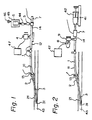
- Figure 1 is a diagram illustrating the state where an indwelling needle and a liquid pouring mechanism are attached to one embodiment of the living body component-measuring instrument of the present invention.
- Figure 2 is a diagram illustrating another embodiment of the present invention. In the embodiment illustrated in Fig.
- the mechanism for introducing blood at least into a fine tube portion 21 of an indwelling needle or indwelling catheter 2 intermittently or periodically when the indwelling needle or indwelling catheter 2 is connected to a fine tube 1 and then discharging blood into the blood vessel is a mechanism for intermittently or periodically pressing and unpressing a wall of the fine tube 1, at least a part of which has an elasticity such that said part of the wall is deformed by an external pressure and the original shape is restored under application of a pressure lower than said external pressure or when said external pressure is released.
- a means for pressing the wall intermittently or periodically there can be adopted, as shown in Fig. 1, a device 4 performing a piston motion, or an eccentric cam 8 (see Fig. 2).
- the fine tube may be bent and stretched to change the inner volume of the fine tube.
- the above-mentioned mechanism comprises an inner volume-variable hollow portion connected only to the interior of the fine tube and a mechanism for applying a pressure to the hollow portion and releasing at least a part of the pressure, and a balloon 9 is used as the inner volumevariable hollow portion.
- An injection syringe may be used instead of the balloon.
- a mechanism similar to the above-mentioned mechanism for pressing the fine tube can be adopted as the pressure-applying mechanism. Furthermmore, a pneumatic pressure can be used.
- a method may be adopted in which injection of the blood anticoagulant solution is effected by an infusion pump 41 and an injection syringe 42 in combination and the blood anticoagulant solution is injected and is caused to flow backward.
- a subatmospheric pressure can be used as the pressure to be applied.
- Fig. 1 The function exerted when the instrument of the present invention is used will now be described with reference to Fig. 1.
- the indwelling needle 2 is inserted and kept in the blood vessel 43, the indwelling needle 2 is connected to the connection portion 13 of the fine tube 1 of the instrument of the present invention.
- An I.V. solution bag 6 is connected to the top of the infusion portion 14 of the fine tube through a high-resistance tube 5, and the blood anticoagulant solution is continuously infused at a constant rate.
- the blood anticoagulant solution or a mixture thereof with blood is present around the living body component-measuring sensor 3, and thus, coagulation of blood on the surface of the sensor or adhesion of proteins to the surface of the sensor can be minimized, with the result that the probability of occurrence of an error is greatly reduced. It is sufficient if the rate of infusing the blood anticoagulant solution is 0.5 to several ml/hr, and of course, a higher injection rate may be adopted.
- the supply pressure of the blood anticoagulant solution be about 300 mmHg, but various pressures may be set according to need.
- the fine tube is pressed by the piston movement device 4 periodically or intermittently to deform the fine tube at least partially, whereby the blood anticoagulant solution is pushed out from the indwelling needle. If the pressure is then released, since the blood anticoagulant solution is not sufficiently infused, blood in the blood vessel 43 is introduced into the indwelling needle 2.
- the piston movement device there can be mentioned, for example, a device in which a shaft is vertically moved by using a solenoid.
- the amount of introduced blood is such that blood reaches the sensing portion 31 of the blood component-measuring sensor 3 which is present in the fine tube portion of the indwelling needle, and the amount of introduced blood need not exceed this level. If blood is introduced in too large an amount, a long time is required for substitution of the introduced blood with the blood anticoagulant solution and for example, in order to improve the response characteristic, a relatively large amount of blood must be introduced and discharged at a high speed.
- the amount of introduced blood is adjusted so that blood gas beyond the indwelling needle but does reach the fine tube 1.
- This adjustment of the amount of introduced blood is accomplished by appropriately controlling the volumes of the indwelling needle and its top end portion (from the top end of the sensing portion of the sensor), the infusion rate of the blood anticoagulant solution and the rate and quantity of the change of the inner volume of the fine tube caused when the deformed fine tube is restored to its original shape.
- An electrode (living body component-measuring sensor 3) comprising a platinum wire having a diameter of 150 mm and having the periphery covered with an insulating coating layer and the top end covered with a porous polyurethane membrane was inserted into an extension tube having at one end a connection portion 13 to be connected to an indwelling needle and a three-way stop cock at the other end, so that when the top end of the electrode was extended from the connection portion 13 and an indwelling needle 2 (Surflow ® indwelling needle 22G supplied by Terumo Corp.) was connected, the porous membrane portion on the top end of the electrode (sensing portion 31 of the living body component-measuring sensor) was located about 1 mm on the inner side from the top end of the indwelling needle.
- an indwelling needle 2 Sudflow ® indwelling needle 22G supplied by Terumo Corp.
- the other end of the electrode was taken out from a hole formed in the wall of the extension tube and the hole was inserted into the femoral artery of a beagle dog (having a body weight of about 10 kg) under the artificcial respiration and intravenous anesthesia, and the indwelling needle was connected to the connection portion of the extension tube so that the electrode was inserted into the indwelling needle.
- a polyvinyl chloride tube 12 having an inner diameter of 1 mm was connected to the three-way stop cock of the extension tube and an I.V. solution bag 6 was connected to this tube 12 through a high-resistance tube 5 (Intraflow ® supplied by Abbot Co.).
- a physiological saline solution containing sodium heparin in an amount of 4 u/ml as the heparin unit was in the I.V. solution bag.
- One end of the high-resistance tube was connected to a pressure transducer and the supply pressure of the heparin solution was adjusted to 300 mmHg.
- the oxygen electrode, reference electrode and temperature sensor were connected to a PO2 monitor device (Model PO-2080 supplied by Mitsubishi Rayon Co.), and the measurement was started.
- the polyvinyl tube 12 was placed between a solenoid (push type tubular solenoid supplied by Shindengen Kogyo K.K.) and a stand placed below the solenoid and compression/release was repeated at a frequency of one time per second along a length of 5mm, a quick response to the change of FiO2 was obtained and a good correlativity to the blood gas analysis value obtained by performing the measurement on collected blood was obtained.
- the correlative coefficient r was as high as 0.98 in the PO2 range of 10 to 600 mmHg when the measurement was continuously conducted for 12 hours. This good correlativity was maintained during the measurement and the measurement could be carried out stably.
- the oxygen electrode and indwelling needle were taken out from the artery and were examined with the naked eye. A formation of thrombs in the indwelling needle or on the porous membrane on the top end of the oxygen electrode was not observed.
- Example 2 The same polyvinyl chloride tube as used in Example 1 was disposed between a high-resistance tube 5 and a pressure transducer 7 and a solenoid was attached thereto.
- the polyvinyl chloride tube was instantaneously compressed at a frequency of one time per 5 seconds and quickly released. Other conditions were the same as described in Example 1.
- the time required for the initial stabilization of the PO2 value obtained by a monitor was as short as about 15 minutes, and a quick response to the change of FiO2 was obtained and the continuous measurement could be conducted stably for 15 hours.
- the correlativity to the blood gas analysis value was good. In the blood pressure simultaneously monitored, some noises appeared owing to compression of the tube at a frequency of one time per 5 seconds, but the blood pressure was monitored without any practical trouble.
- a sensor 3 of an oxygen saturation degree-measuring apparatus for measuring the oxygen saturation degree in the blood from the absorbancy by using optical fibers was build in an extension tube 11 having at one end a connection portion 13 to be connected to an indwelling needle 2 and a three-way stop cock at the other end, and a Surflow ® indwelling needle 14G (supplied by Terumo Corp.) was used as the indwelling needle and the sensor was fixed to the extension tube so that when the indwelling needle was connected, the sensing portion 31 of the sensor was located about 3 mm on the inner side from the tope end of the indwelling needle.
- a physiological saline solution containing sodium heparin in an amount of 4 u/ml as the heparin unit was charged in a syringe 42 having a capacity of 50 ml and the syringe was set to an infusion pump 41.
- the indwelling needle was inserted into the ascending vena cava through the ingular vein in a beagle dog having a body weight of about 8 kg under the artificial respiration and intravenous anesthesia, and the indwelling needle was connected to the connection portion of the extension tube so that the sensor was inserted into the indwelling needle.
- the three-way stop cock of the extension tube having the sensor built therein was connected to the syringe filled with the heparin solution through an extension tube provided with a rotary type three-way stop cock, and a balloon 9 having an inner capacity of 0.1 ml formed of a silicone rubber such as a balloon to be attached to a pipette was connected to a non-used connection terminal of the rotary type three-way stop cock to form a line for infusing the heparin solution. Air in the infusion line and balloon was substituted with the heparin solution, and continuous infusion of the heparin solution at an injection rate of 2 ml/hr was initiated.
- the balloon was compressed for about 0.3 second at a frequency of one time per 2 seconds and was then quickly released.
- the eccentric cam was continuously operated so that the above-mentioned compression/release was repeated. In this state, the measurement was initiated.
- the respirator was operated to change the oxygen saturation degree of the vein within the range of from about 10 to about 90%.
- Example 3 The procedures of Example 3 were repeated in the same manner except that a beagle dog having a body weight of 15 kg was used as the test animal, the Surflow ® indwelling needle 14G was inserted in the femoral vein so that when the indwelling needle was connected, the sensing portion of the sensor was located about 2 mm on the inner side from the top end of the indwelling needle, the three-way stop cock of the extension tube was connected to the syringe for infusing the heparin solution through the extension tube, and the extension tube was subjected to compression/release repeatedly along a length of 2 mm at a frequency of one time per second by changing the rotation direction of the eccentric cam according to the infusion of the heparting solution.
- the measurement could be stably conducted for 15 hours continuously, and a good correlativity was observed between the obtained value and the value of the oxygen saturation degree measured in collected blood.
- the sensing portion of the living body component-measuring sensor is inserted into the blood vessel and the blood component can be measured substantially continuously while maintaining the environment in the living body. Furthermore, since the sensing portion is located within the indwelling needle or indwelling catheter, reduction of the measurement accuracy owing to the contact of the sensing portion with the blood vessel wall is not caused.
- the instrument since the interior of the indwelling needle or indwelling catheter was filled with the blood anticoagulant solution or a mixture thereof with blood in the normal state during the measurement, adhesion of coagulation products of the blood to the sensing portion of the sensor is prevented, and since the instrument has the mechanism for introducing blood into the sensing portion of the sensor within the indwelling needle or indwelling catheter and then discharging blood from the indwelling needle or indwelling catheter by infusion of the blood anticoagulant solution, the blood components can be measured with a high accuracy and the instrument of the present invention is suitable for the continuous measurement conducted for a long time.
- An ordinary line for infusion of a blood anticoagulant which is customarily used when an indwelling needle or the like is disposed can be utilized in the present invention, and therefore, it is not necessary to infuse the blood anticoagulant in an excessive amount.
Claims (6)
- Vorrichtung enthaltend eine Kombination aus einem Instrument zur Messung von Komponenten des lebenden Körpers und einer intravaskulären Nadel oder einem intravaskulären Katheter (2), bei der das Instrument zur Messung von Komponenten des lebenden Körpers aufweist: ein feines Rohr (1), das an seinem einen Ende mit einem Verbindungsbereich (13) versehen ist, welcher im Gebrauch an die intravaskuläre Nadel oder den intravaskulären Katheter (2) angeschlossen ist; einen Infusionsbereich (14), von dem aus mindestens eine Lösung eines Blutantikoagulantiums infundiert werden kann; einen feinen linearen Fühler (3) zur Messung von Komponenten des lebenden Körpers mit einem beim Gebrauch innerhalb eines feinen Rohrbereichs (21) der intravaskulären Nadel oder des intravaskulären Katheters gelegenen Fühlerbereich; und einen Mechanismus (4; 8, 9), der im Gebrauch dazu dient, Blut mindestens in das Innere des feinen Rohrbereichs (21) der intravaskulären Nadel oder des intravaskulären Katheters (2) intermittierend oder periodisch einzuführen, wenn die intravaskuläre Nadel oder der intravaskuläre Katheter (2) in dem Blutgefäß belassen ist, und dann Blut in das Blutgefäß auszustoßen, dadurch gekennzeichnet, daß der Fühler sich vom Inneren des feinen Rohrs durch den Verbindungsbereich nach außen erstreckt, der Fühlerbereich des Fühlers (3) an einem um 10 mm oder weniger von dem Auslaßende der intravaskulären Nadel oder des intravaskulären Katheters beabstandeten Punkt gelegen ist, wenn die intravaskuläre Nadel oder der intravaskuläre Katheter an den Verbindungsbereich des feinen Rohrs (1) angeschlossen ist, und daß die intravaskuläre Nadel oder der intravaskuläre Katheter (2) von dem Instrument getrennt ausgebildet ist und zum Gebrauch an dessen Verbindungsbereich (13) anschließbar ist.
- Vorrichtung nach Anspruch 1, bei der der Mechanismus (4) eine Einrichtung zur intermittierenden oder periodischen Anlegung eines Drucks an die Wand des feinen Rohrs (1) und zur Entlastung dieses Drucks aufweist, wobei mindestens ein Teil der Wand des feinen Rohrs (1) eine derartige Elastizität aufweist, daß der Teil der Wand unter der Anwendung eines äußeren Drucks verformt und anschließend die ursprüngliche Form dieses Teils der Wand wiederhergestellt wird, wenn ein von dem äußeren Druck unterschiedlicher äußerer Druck angelegt oder der äußere Druck entlastet wird.
- Vorrichtung nach Anspruch 1, bei der der Mechanismus (8, 9) eine Einrichtung zur Begrenzung eines nur mit dem Inneren des feinen Rohrs (1) verbundenen volumenveränderlichen hohlen Bereichs und eine Einrichtung zur intermittierenden oder periodischen Anlegung eines Drucks an den hohlen Bereich und zur Entlastung des Drucks aufweist.
- Vorrichtung nach Anspruch 3, bei der die Einrichtung zur Begrenzung eines volumenveränderlichen hohlen Bereichs ein hohler Ballon ist.
- Vorrichtung nach Anspruch 4, bei der die Einrichtung zur Begrenzung eines volumenveränderlichen hohlen Bereichs eine Spritze ist.
- Vorrichtung nach einem der vorhergehenden Ansprüche, bei der eine Einrichtung zum Einbringen einer Lösung eines Blutantikoagulantiums in das feine Rohr an dessen Infusionsbereich (14) angeschlossen ist.
Applications Claiming Priority (2)
| Application Number | Priority Date | Filing Date | Title |
|---|---|---|---|
| JP306870/86 | 1986-12-23 | ||
| JP61306870A JPS63160635A (ja) | 1986-12-23 | 1986-12-23 | 生体成分測定用具 |
Publications (2)
| Publication Number | Publication Date |
|---|---|
| EP0276535A1 EP0276535A1 (de) | 1988-08-03 |
| EP0276535B1 true EP0276535B1 (de) | 1992-12-30 |
Family
ID=17962236
Family Applications (1)
| Application Number | Title | Priority Date | Filing Date |
|---|---|---|---|
| EP87304569A Expired - Lifetime EP0276535B1 (de) | 1986-12-23 | 1987-05-22 | Apparat zum Messen von Komponenten eines Lebenskörpers |
Country Status (4)
| Country | Link |
|---|---|
| US (1) | US4813423A (de) |
| EP (1) | EP0276535B1 (de) |
| JP (1) | JPS63160635A (de) |
| CA (1) | CA1305530C (de) |
Cited By (1)
| Publication number | Priority date | Publication date | Assignee | Title |
|---|---|---|---|---|
| EP4110184A4 (de) * | 2020-02-24 | 2024-01-24 | Terumo Cardiovascular Sys Corp | Wässriges pufferschutzsystem für biosensoren |
Families Citing this family (31)
| Publication number | Priority date | Publication date | Assignee | Title |
|---|---|---|---|---|
| EP0403683A1 (de) * | 1989-06-23 | 1990-12-27 | Siemens Aktiengesellschaft | Anordnung zur Untersuchung eines flüssigen Messmediums |
| CA2034285A1 (en) * | 1990-02-09 | 1991-08-10 | Masao Yafuso | Method and system for monitoring of blood constituents in vivo |
| JP2974429B2 (ja) * | 1991-02-04 | 1999-11-10 | 徹 新里 | 血液浄化装置 |
| US5271398A (en) * | 1991-10-09 | 1993-12-21 | Optex Biomedical, Inc. | Intra-vessel measurement of blood parameters |
| US5335658A (en) * | 1992-06-29 | 1994-08-09 | Minnesota Mining And Manufacturing Company | Intravascular blood parameter sensing system |
| DE4424267C2 (de) * | 1994-07-09 | 1996-07-11 | Hewlett Packard Gmbh | Vorrichtung zur kontinuierlichen Erfassung von Blutparametern |
| ES2141280T3 (es) * | 1995-05-26 | 2000-03-16 | Schneider Europ Gmbh | Sistema de expansion de endoprotesis utilizando un medio fluido pulsado. |
| US5722979A (en) * | 1997-04-08 | 1998-03-03 | Schneider (Usa) Inc. | Pressure assisted ultrasonic balloon catheter and method of using same |
| AU1631101A (en) * | 1999-10-07 | 2001-05-10 | Pepex Biomedical, Llc | Sensor for measuring a bioanalyte such as lactate |
| US7018336B2 (en) * | 2001-12-27 | 2006-03-28 | Medtronic Minimed, Inc. | Implantable sensor flush sleeve |
| US7096059B2 (en) * | 2002-07-03 | 2006-08-22 | Bioanalytical Systems, Inc. | Device and method for electrocardiography on freely moving animals |
| US8626257B2 (en) | 2003-08-01 | 2014-01-07 | Dexcom, Inc. | Analyte sensor |
| US20190357827A1 (en) | 2003-08-01 | 2019-11-28 | Dexcom, Inc. | Analyte sensor |
| US8364230B2 (en) * | 2006-10-04 | 2013-01-29 | Dexcom, Inc. | Analyte sensor |
| US8425416B2 (en) * | 2006-10-04 | 2013-04-23 | Dexcom, Inc. | Analyte sensor |
| US8425417B2 (en) * | 2003-12-05 | 2013-04-23 | Dexcom, Inc. | Integrated device for continuous in vivo analyte detection and simultaneous control of an infusion device |
| US8774886B2 (en) * | 2006-10-04 | 2014-07-08 | Dexcom, Inc. | Analyte sensor |
| US20080200788A1 (en) * | 2006-10-04 | 2008-08-21 | Dexcorn, Inc. | Analyte sensor |
| US8364231B2 (en) * | 2006-10-04 | 2013-01-29 | Dexcom, Inc. | Analyte sensor |
| US20080197024A1 (en) * | 2003-12-05 | 2008-08-21 | Dexcom, Inc. | Analyte sensor |
| US7468033B2 (en) * | 2004-09-08 | 2008-12-23 | Medtronic Minimed, Inc. | Blood contacting sensor |
| DE102005063411A1 (de) * | 2005-12-15 | 2007-10-11 | Up Management Gmbh & Co Med-Systems Kg | Blutgefäßkatheter und Injektionssystem zum Durchführen einer Blutdruckmessung eines Patienten |
| US8562528B2 (en) * | 2006-10-04 | 2013-10-22 | Dexcom, Inc. | Analyte sensor |
| US8275438B2 (en) * | 2006-10-04 | 2012-09-25 | Dexcom, Inc. | Analyte sensor |
| US8478377B2 (en) * | 2006-10-04 | 2013-07-02 | Dexcom, Inc. | Analyte sensor |
| US8298142B2 (en) * | 2006-10-04 | 2012-10-30 | Dexcom, Inc. | Analyte sensor |
| US8449464B2 (en) * | 2006-10-04 | 2013-05-28 | Dexcom, Inc. | Analyte sensor |
| US8447376B2 (en) * | 2006-10-04 | 2013-05-21 | Dexcom, Inc. | Analyte sensor |
| US9801575B2 (en) | 2011-04-15 | 2017-10-31 | Dexcom, Inc. | Advanced analyte sensor calibration and error detection |
| DE102009017033A1 (de) * | 2009-04-09 | 2010-10-21 | Pulsion Medical Systems Ag | Blasenkatheter zur Messung des Drucks in der Blase eines Lebewesens |
| WO2012159040A2 (en) | 2011-05-19 | 2012-11-22 | Pepex Biomedical Inc. | Fluid management and patient monitoring system |
Citations (1)
| Publication number | Priority date | Publication date | Assignee | Title |
|---|---|---|---|---|
| DE3038883A1 (de) * | 1980-10-15 | 1982-07-29 | Dr. Eduard Fresenius, Chemisch-pharmazeutische Industrie KG Apparatebau KG, 6380 Bad Homburg | Messsonde und verfahren zu ihrer anwendung |
Family Cites Families (7)
| Publication number | Priority date | Publication date | Assignee | Title |
|---|---|---|---|---|
| CH539437A (de) * | 1971-09-23 | 1973-07-31 | Siemens Ag | Vorrichtung für medizinische Zwecke zum Infundieren einer Flüssigkeit, insbesondere bei blutiger Blutdruckmessung |
| IT1158880B (it) * | 1978-07-05 | 1987-02-25 | Sclavo Inst Sieroterapeut | Dispositivo per l'esecuzione di misure su fluidi direttamente nel contenitore di prelievo del campione |
| DE2946660A1 (de) * | 1979-03-07 | 1981-05-27 | C.A. Greiner und Söhne GmbH & Co KG, 7440 Nürtingen | Blutentnahmegeraet |
| JPS56113084A (en) * | 1980-02-12 | 1981-09-05 | Terumo Corp | Pulsation preventing method and device for peristaltic finger pump |
| US4442841A (en) * | 1981-04-30 | 1984-04-17 | Mitsubishi Rayon Company Limited | Electrode for living bodies |
| US4622974A (en) * | 1984-03-07 | 1986-11-18 | University Of Tennessee Research Corporation | Apparatus and method for in-vivo measurements of chemical concentrations |
| JPS6340532A (ja) * | 1986-04-05 | 1988-02-20 | 日本光電工業株式会社 | 血液成分の監視装置 |
-
1986
- 1986-12-23 JP JP61306870A patent/JPS63160635A/ja active Pending
-
1987
- 1987-05-22 CA CA000537741A patent/CA1305530C/en not_active Expired - Lifetime
- 1987-05-22 US US07/052,903 patent/US4813423A/en not_active Expired - Fee Related
- 1987-05-22 EP EP87304569A patent/EP0276535B1/de not_active Expired - Lifetime
Patent Citations (1)
| Publication number | Priority date | Publication date | Assignee | Title |
|---|---|---|---|---|
| DE3038883A1 (de) * | 1980-10-15 | 1982-07-29 | Dr. Eduard Fresenius, Chemisch-pharmazeutische Industrie KG Apparatebau KG, 6380 Bad Homburg | Messsonde und verfahren zu ihrer anwendung |
Non-Patent Citations (1)
| Title |
|---|
| Med. and Biol Eng & Comp., July 1985, 23, pages 329-338; Sibbald et al: "On line Patient monitoring System...." * |
Cited By (1)
| Publication number | Priority date | Publication date | Assignee | Title |
|---|---|---|---|---|
| EP4110184A4 (de) * | 2020-02-24 | 2024-01-24 | Terumo Cardiovascular Sys Corp | Wässriges pufferschutzsystem für biosensoren |
Also Published As
| Publication number | Publication date |
|---|---|
| US4813423A (en) | 1989-03-21 |
| CA1305530C (en) | 1992-07-21 |
| JPS63160635A (ja) | 1988-07-04 |
| EP0276535A1 (de) | 1988-08-03 |
Similar Documents
| Publication | Publication Date | Title |
|---|---|---|
| EP0276535B1 (de) | Apparat zum Messen von Komponenten eines Lebenskörpers | |
| US5330634A (en) | Calibration solutions useful for analyses of biological fluids and methods employing same | |
| US6123827A (en) | Method for calibrating sensors used in diagnostic testing | |
| JP2939340B2 (ja) | 流体を送出および収集する方法 | |
| EP0401179B1 (de) | Kunst-Pankreas | |
| US5193545A (en) | Device for determining at least one medical variable | |
| US6254586B1 (en) | Method and kit for supplying a fluid to a subcutaneous placement site | |
| US6413238B1 (en) | Fluid dispenser with stabilized fluid flow | |
| EP0134758A2 (de) | Vorrichtung für die kontrollierte Infusion von Insulin oder Glucose bei Diabetespatienten | |
| WO1991016416A1 (en) | Wearable blood glucose monitor | |
| EP0441394A2 (de) | Verfahren und Vorrichtung zum Messen von Blutbestandteilen in vivo | |
| EP2419008A1 (de) | Medizinische vorrichtung zur überwachung oder regulierung des blutzuckerspiegels | |
| US5687718A (en) | Device for continuously detecting blood parameters | |
| US20070123775A1 (en) | Method and device for monitoring infusions | |
| Clarke et al. | The characteristics of a new glucose sensor for use in an artificial pancreatic beta cell | |
| JPH06237935A (ja) | トノメトリーカテーテル装置、それを用いた液流体または気体流体の特性を表示測定する方法および化合物を分析する方法 | |
| JPS6317448B2 (de) | ||
| Christiansen et al. | An artificial betacell: assessment of the glucose analyser, infusion system and optimization of constants for the algorithms | |
| WO1981003426A1 (en) | Arterial blood sampling device for blood gas analysis | |
| JPH0345686Y2 (de) | ||
| JPH0256889B2 (de) | ||
| JPH0417050B2 (de) | ||
| JPH0417049B2 (de) | ||
| JPH0368692B2 (de) | ||
| JPS60116332A (ja) | 血液中の気体濃度測定用装置 |
Legal Events
| Date | Code | Title | Description |
|---|---|---|---|
| PUAI | Public reference made under article 153(3) epc to a published international application that has entered the european phase |
Free format text: ORIGINAL CODE: 0009012 |
|
| AK | Designated contracting states |
Kind code of ref document: A1 Designated state(s): DE FR GB SE |
|
| 17P | Request for examination filed |
Effective date: 19880813 |
|
| 17Q | First examination report despatched |
Effective date: 19910320 |
|
| GRAA | (expected) grant |
Free format text: ORIGINAL CODE: 0009210 |
|
| RBV | Designated contracting states (corrected) |
Designated state(s): GB |
|
| AK | Designated contracting states |
Kind code of ref document: B1 Designated state(s): GB |
|
| REG | Reference to a national code |
Ref country code: DE Ref legal event code: 8566 |
|
| PLBE | No opposition filed within time limit |
Free format text: ORIGINAL CODE: 0009261 |
|
| STAA | Information on the status of an ep patent application or granted ep patent |
Free format text: STATUS: NO OPPOSITION FILED WITHIN TIME LIMIT |
|
| 26N | No opposition filed | ||
| PGFP | Annual fee paid to national office [announced via postgrant information from national office to epo] |
Ref country code: GB Payment date: 19940512 Year of fee payment: 8 |
|
| PG25 | Lapsed in a contracting state [announced via postgrant information from national office to epo] |
Ref country code: GB Effective date: 19950522 |
|
| GBPC | Gb: european patent ceased through non-payment of renewal fee |
Effective date: 19950522 |