EP0275977A2 - Composite coatings - Google Patents
Composite coatings Download PDFInfo
- Publication number
- EP0275977A2 EP0275977A2 EP88100690A EP88100690A EP0275977A2 EP 0275977 A2 EP0275977 A2 EP 0275977A2 EP 88100690 A EP88100690 A EP 88100690A EP 88100690 A EP88100690 A EP 88100690A EP 0275977 A2 EP0275977 A2 EP 0275977A2
- Authority
- EP
- European Patent Office
- Prior art keywords
- article according
- al2o3
- phase
- zro2
- layer
- Prior art date
- Legal status (The legal status is an assumption and is not a legal conclusion. Google has not performed a legal analysis and makes no representation as to the accuracy of the status listed.)
- Granted
Links
- 239000002131 composite material Substances 0.000 title claims abstract description 36
- 238000000576 coating method Methods 0.000 title description 31
- MCMNRKCIXSYSNV-UHFFFAOYSA-N Zirconium dioxide Chemical compound O=[Zr]=O MCMNRKCIXSYSNV-UHFFFAOYSA-N 0.000 claims abstract description 55
- 239000002245 particle Substances 0.000 claims abstract description 34
- PNEYBMLMFCGWSK-UHFFFAOYSA-N aluminium oxide Inorganic materials [O-2].[O-2].[O-2].[Al+3].[Al+3] PNEYBMLMFCGWSK-UHFFFAOYSA-N 0.000 claims abstract description 33
- 239000000758 substrate Substances 0.000 claims abstract description 32
- 239000000463 material Substances 0.000 claims abstract description 23
- 239000000919 ceramic Substances 0.000 claims abstract description 21
- RUDFQVOCFDJEEF-UHFFFAOYSA-N yttrium(III) oxide Inorganic materials [O-2].[O-2].[O-2].[Y+3].[Y+3] RUDFQVOCFDJEEF-UHFFFAOYSA-N 0.000 claims abstract description 17
- 229910052726 zirconium Inorganic materials 0.000 claims abstract description 13
- 229910052782 aluminium Inorganic materials 0.000 claims abstract description 11
- QCWXUUIWCKQGHC-UHFFFAOYSA-N Zirconium Chemical compound [Zr] QCWXUUIWCKQGHC-UHFFFAOYSA-N 0.000 claims abstract description 10
- XAGFODPZIPBFFR-UHFFFAOYSA-N aluminium Chemical compound [Al] XAGFODPZIPBFFR-UHFFFAOYSA-N 0.000 claims abstract description 10
- 229910052727 yttrium Inorganic materials 0.000 claims abstract description 9
- VWQVUPCCIRVNHF-UHFFFAOYSA-N yttrium atom Chemical compound [Y] VWQVUPCCIRVNHF-UHFFFAOYSA-N 0.000 claims abstract description 9
- 238000005524 ceramic coating Methods 0.000 claims abstract description 3
- 229910052593 corundum Inorganic materials 0.000 claims description 29
- 229910001845 yogo sapphire Inorganic materials 0.000 claims description 29
- ATJFFYVFTNAWJD-UHFFFAOYSA-N Tin Chemical compound [Sn] ATJFFYVFTNAWJD-UHFFFAOYSA-N 0.000 claims description 8
- 230000001464 adherent effect Effects 0.000 claims description 6
- 150000004767 nitrides Chemical class 0.000 claims description 5
- 150000001247 metal acetylides Chemical class 0.000 claims description 4
- 229910052710 silicon Inorganic materials 0.000 claims description 4
- 229910052581 Si3N4 Inorganic materials 0.000 claims description 3
- 229910052796 boron Inorganic materials 0.000 claims description 3
- 229910052804 chromium Inorganic materials 0.000 claims description 3
- 229910052735 hafnium Inorganic materials 0.000 claims description 3
- 229910052750 molybdenum Inorganic materials 0.000 claims description 3
- 229910052715 tantalum Inorganic materials 0.000 claims description 3
- 229910052719 titanium Inorganic materials 0.000 claims description 3
- 229910052721 tungsten Inorganic materials 0.000 claims description 3
- 229910009043 WC-Co Inorganic materials 0.000 claims description 2
- 239000011159 matrix material Substances 0.000 abstract description 33
- 238000005520 cutting process Methods 0.000 abstract description 10
- 239000006104 solid solution Substances 0.000 abstract description 3
- 230000002844 continuous effect Effects 0.000 abstract 1
- 239000007789 gas Substances 0.000 description 22
- 239000011248 coating agent Substances 0.000 description 20
- 229910052751 metal Inorganic materials 0.000 description 19
- 239000002184 metal Substances 0.000 description 19
- 238000000151 deposition Methods 0.000 description 17
- 230000008021 deposition Effects 0.000 description 16
- 238000000034 method Methods 0.000 description 11
- 150000004820 halides Chemical class 0.000 description 10
- 239000000203 mixture Substances 0.000 description 9
- 229910001507 metal halide Inorganic materials 0.000 description 8
- 150000005309 metal halides Chemical class 0.000 description 8
- 150000002739 metals Chemical class 0.000 description 7
- 150000001875 compounds Chemical class 0.000 description 6
- 238000009826 distribution Methods 0.000 description 6
- VSCWAEJMTAWNJL-UHFFFAOYSA-K aluminium trichloride Chemical compound Cl[Al](Cl)Cl VSCWAEJMTAWNJL-UHFFFAOYSA-K 0.000 description 4
- 238000005229 chemical vapour deposition Methods 0.000 description 4
- 239000000376 reactant Substances 0.000 description 4
- 239000012159 carrier gas Substances 0.000 description 3
- 229910010293 ceramic material Inorganic materials 0.000 description 3
- 238000006243 chemical reaction Methods 0.000 description 3
- 238000003754 machining Methods 0.000 description 3
- 239000000126 substance Substances 0.000 description 3
- IJGRMHOSHXDMSA-UHFFFAOYSA-N Atomic nitrogen Chemical compound N#N IJGRMHOSHXDMSA-UHFFFAOYSA-N 0.000 description 2
- 229910000831 Steel Inorganic materials 0.000 description 2
- 229910007932 ZrCl4 Inorganic materials 0.000 description 2
- CSDREXVUYHZDNP-UHFFFAOYSA-N alumanylidynesilicon Chemical compound [Al].[Si] CSDREXVUYHZDNP-UHFFFAOYSA-N 0.000 description 2
- 239000008246 gaseous mixture Substances 0.000 description 2
- 239000001257 hydrogen Substances 0.000 description 2
- 229910052739 hydrogen Inorganic materials 0.000 description 2
- 125000004435 hydrogen atom Chemical class [H]* 0.000 description 2
- 238000005240 physical vapour deposition Methods 0.000 description 2
- 239000010959 steel Substances 0.000 description 2
- DUNKXUFBGCUVQW-UHFFFAOYSA-J zirconium tetrachloride Chemical compound Cl[Zr](Cl)(Cl)Cl DUNKXUFBGCUVQW-UHFFFAOYSA-J 0.000 description 2
- VEXZGXHMUGYJMC-UHFFFAOYSA-N Hydrochloric acid Chemical compound Cl VEXZGXHMUGYJMC-UHFFFAOYSA-N 0.000 description 1
- 208000036366 Sensation of pressure Diseases 0.000 description 1
- XUIMIQQOPSSXEZ-UHFFFAOYSA-N Silicon Chemical compound [Si] XUIMIQQOPSSXEZ-UHFFFAOYSA-N 0.000 description 1
- 238000002441 X-ray diffraction Methods 0.000 description 1
- 229910009474 Y2O3—ZrO2 Inorganic materials 0.000 description 1
- 229910009523 YCl3 Inorganic materials 0.000 description 1
- 238000005299 abrasion Methods 0.000 description 1
- 230000015556 catabolic process Effects 0.000 description 1
- 230000000052 comparative effect Effects 0.000 description 1
- 230000001276 controlling effect Effects 0.000 description 1
- 239000002537 cosmetic Substances 0.000 description 1
- 238000005137 deposition process Methods 0.000 description 1
- 238000004519 manufacturing process Methods 0.000 description 1
- 229910001510 metal chloride Inorganic materials 0.000 description 1
- 229910001092 metal group alloy Inorganic materials 0.000 description 1
- 238000005065 mining Methods 0.000 description 1
- 238000012986 modification Methods 0.000 description 1
- 230000004048 modification Effects 0.000 description 1
- 229910052757 nitrogen Inorganic materials 0.000 description 1
- 238000010943 off-gassing Methods 0.000 description 1
- 230000001590 oxidative effect Effects 0.000 description 1
- 150000003839 salts Chemical class 0.000 description 1
- 238000000926 separation method Methods 0.000 description 1
- 239000010703 silicon Substances 0.000 description 1
- PCMOZDDGXKIOLL-UHFFFAOYSA-K yttrium chloride Chemical compound [Cl-].[Cl-].[Cl-].[Y+3] PCMOZDDGXKIOLL-UHFFFAOYSA-K 0.000 description 1
Images
Classifications
-
- C—CHEMISTRY; METALLURGY
- C23—COATING METALLIC MATERIAL; COATING MATERIAL WITH METALLIC MATERIAL; CHEMICAL SURFACE TREATMENT; DIFFUSION TREATMENT OF METALLIC MATERIAL; COATING BY VACUUM EVAPORATION, BY SPUTTERING, BY ION IMPLANTATION OR BY CHEMICAL VAPOUR DEPOSITION, IN GENERAL; INHIBITING CORROSION OF METALLIC MATERIAL OR INCRUSTATION IN GENERAL
- C23C—COATING METALLIC MATERIAL; COATING MATERIAL WITH METALLIC MATERIAL; SURFACE TREATMENT OF METALLIC MATERIAL BY DIFFUSION INTO THE SURFACE, BY CHEMICAL CONVERSION OR SUBSTITUTION; COATING BY VACUUM EVAPORATION, BY SPUTTERING, BY ION IMPLANTATION OR BY CHEMICAL VAPOUR DEPOSITION, IN GENERAL
- C23C30/00—Coating with metallic material characterised only by the composition of the metallic material, i.e. not characterised by the coating process
- C23C30/005—Coating with metallic material characterised only by the composition of the metallic material, i.e. not characterised by the coating process on hard metal substrates
-
- C—CHEMISTRY; METALLURGY
- C04—CEMENTS; CONCRETE; ARTIFICIAL STONE; CERAMICS; REFRACTORIES
- C04B—LIME, MAGNESIA; SLAG; CEMENTS; COMPOSITIONS THEREOF, e.g. MORTARS, CONCRETE OR LIKE BUILDING MATERIALS; ARTIFICIAL STONE; CERAMICS; REFRACTORIES; TREATMENT OF NATURAL STONE
- C04B41/00—After-treatment of mortars, concrete, artificial stone or ceramics; Treatment of natural stone
- C04B41/45—Coating or impregnating, e.g. injection in masonry, partial coating of green or fired ceramics, organic coating compositions for adhering together two concrete elements
- C04B41/50—Coating or impregnating, e.g. injection in masonry, partial coating of green or fired ceramics, organic coating compositions for adhering together two concrete elements with inorganic materials
- C04B41/5025—Coating or impregnating, e.g. injection in masonry, partial coating of green or fired ceramics, organic coating compositions for adhering together two concrete elements with inorganic materials with ceramic materials
-
- C—CHEMISTRY; METALLURGY
- C04—CEMENTS; CONCRETE; ARTIFICIAL STONE; CERAMICS; REFRACTORIES
- C04B—LIME, MAGNESIA; SLAG; CEMENTS; COMPOSITIONS THEREOF, e.g. MORTARS, CONCRETE OR LIKE BUILDING MATERIALS; ARTIFICIAL STONE; CERAMICS; REFRACTORIES; TREATMENT OF NATURAL STONE
- C04B41/00—After-treatment of mortars, concrete, artificial stone or ceramics; Treatment of natural stone
- C04B41/45—Coating or impregnating, e.g. injection in masonry, partial coating of green or fired ceramics, organic coating compositions for adhering together two concrete elements
- C04B41/52—Multiple coating or impregnating multiple coating or impregnating with the same composition or with compositions only differing in the concentration of the constituents, is classified as single coating or impregnation
-
- C—CHEMISTRY; METALLURGY
- C04—CEMENTS; CONCRETE; ARTIFICIAL STONE; CERAMICS; REFRACTORIES
- C04B—LIME, MAGNESIA; SLAG; CEMENTS; COMPOSITIONS THEREOF, e.g. MORTARS, CONCRETE OR LIKE BUILDING MATERIALS; ARTIFICIAL STONE; CERAMICS; REFRACTORIES; TREATMENT OF NATURAL STONE
- C04B41/00—After-treatment of mortars, concrete, artificial stone or ceramics; Treatment of natural stone
- C04B41/80—After-treatment of mortars, concrete, artificial stone or ceramics; Treatment of natural stone of only ceramics
- C04B41/81—Coating or impregnation
- C04B41/85—Coating or impregnation with inorganic materials
- C04B41/87—Ceramics
-
- C—CHEMISTRY; METALLURGY
- C04—CEMENTS; CONCRETE; ARTIFICIAL STONE; CERAMICS; REFRACTORIES
- C04B—LIME, MAGNESIA; SLAG; CEMENTS; COMPOSITIONS THEREOF, e.g. MORTARS, CONCRETE OR LIKE BUILDING MATERIALS; ARTIFICIAL STONE; CERAMICS; REFRACTORIES; TREATMENT OF NATURAL STONE
- C04B41/00—After-treatment of mortars, concrete, artificial stone or ceramics; Treatment of natural stone
- C04B41/80—After-treatment of mortars, concrete, artificial stone or ceramics; Treatment of natural stone of only ceramics
- C04B41/81—Coating or impregnation
- C04B41/89—Coating or impregnation for obtaining at least two superposed coatings having different compositions
Definitions
- This invention relates to an article comprising a wear resistant coating deposited on a cemented carbide or hard ceramic substrate, and more particularly to an article having a two or more phase composite oxide coating deposited on such a substrate.
- Cemented carbide and hard ceramic materials are known and are used extensively in such applications as mining tool bits, metal cutting and boring tools, metal drawing dies, wear-resistant machine parts and the like.
- Hard ceramic materials refers to such compositions as Al2O3, Si3N4, silicon aluminum oxynitride and related compounds, as hard and dense monolithic or composite materials.
- the composites include those containing whiskers and/or particulates of SiC, Si3N4, other ceramic materials, and metal carbides, nitrides, and carbonitrides such as TiC and TiN. It is also known that the service properties such as wear, high temperature and chemical resistance of such materials may be enhanced by the application of one or more thin coatings of, for example, metal carbides, metal nitrides, or ceramics.
- a wear resistant article according to the invention comprises a cemented carbide or hard ceramic substrate body having a fully dense, adherent, wear resistant, composite ceramic coating having at least two phases on the substrate.
- the coating comprises a continuous oxide layer about 0.1-20 microns thick of a material selected from the oxides of aluminum, zirconium, and yttrium.
- At least one discontinuous additional phase is dispersed as discrete particles within the oxide layer, the additional phase being of at least one material selected from the oxides of aluminum, zirconium, and yttrium, the material being different from that of the oxide layer.
- At least one intermediate layer is deposited between the substrate body and the composite ceramic layer.
- the intermediate layer is about 0.5-10 microns thick and is of one or more materials selected from the carbides, nitrides, and carbonitrides of Ti, Zr, Hf, Va, Nb, Ta, Cr, Mo, W, Si, and B.
- the additional phase may be evenly dispersed within the continuous oxide layer, or the composite ceramic layer may be a stratified layer,
- the article according to the present invention may be prepared by deposition of an adherent two or more phase composite oxide-based coating on a cemented metal carbide substrate, for example, a WC-Co or related material, or on a hard ceramic substrate for example a monolithic or composite alumina-, silicon nitride-, or silicon aluminum oxynitride-based material or related material.
- a cemented metal carbide substrate for example, a WC-Co or related material
- a hard ceramic substrate for example a monolithic or composite alumina-, silicon nitride-, or silicon aluminum oxynitride-based material or related material.
- the outstanding properties of the coating are a result of the second phase of discrete particles of Al2O3, ZrO2, or Y2O3, or a combination of these, within an Al2O3, ZrO2, or Y2O3 matrix.
- the preferred coatings include ZrO2 particles and/or Y2O3 particles within a continuous Al2O3 matrix, Y2O3 particles within a continuous ZrO2 matrix, ZrO2 particles within a continuous Y2O3 matrix, or Y2O3 stabilized ZrO2 particles, i.e. of an Y2O3-ZrO2 solid solution, within a continuous Al2O3 matrix.
- the particles may be evenly distributed throughout the matrix, or their distribution may be controlled to achieve, for example, a stratified structure of single-phase oxide matrix portions alternating with two or more phase matrix/particle portions, preferably disposed at controlled intervals throughout the matrix.
- the deposition may be controlled to deposit a single-phase continuous portion of controlled depth of the matrix material below the two or more phase portion of the coating.
- the preferred process for preparing the articles according to the invention involves the use of a mixture of gases including a mixture of metal halides and other reactant gases under carefully controlled conditions to deposit by chemical vapor deposition (CVD) compounds of the metals on a substrate.
- the preferred process involves passing over the substrate a first gaseous mixture of a first halide vapor selected from the halides of aluminum, yttrium and zirconium, with other reactant gases, and optionally a carrier gas.
- the temperature is about 900°-1250°C for cemented carbide substrates or about 900°-1500°C for hard ceramic substrates, and the pressure between about 1 torr and about ambient pressure.
- the partial pressure ratios, the flow rate, and the length of time is sufficient to deposit a continuous, fully dense, adherent, wear resistant layer of a material selected from the oxides of aluminum, zirconium, and yttrium about 0.1-20 microns thick on the substrate. At least one additional vapor selected from the halides of aluminum, zirconium, and yttrium is mixed with the first gaseous mixture.
- the additional metal halide vapor is different from the first halide vapor, and is mixed at a partial pressure selected to form at least one discontinuous additional phase, dispersed as discrete particles within the continuous oxide layer, of at least one material selected from the oxides of aluminum, zirconium, and yttrium, to form a wear resistant composite ceramic layer on the substrate.
- the article may be produced by appropriate physical vapor deposition (PVD) techniques.
- the metal halides are produced by passing halide gas or gases over the metals, for example metal particulates.
- the metals maybe combined as a mixture of metals, as a metal alloy, or as metal salts.
- a single halide gas is passed over the combined metals to form a mixture of metal halides.
- at least the metal forming the matrix is separate, and separate halide gas streams are passed over the metals to form separate metal halides, which are later combined.
- Carrier gases for example Ar, may be combined with the halide gases.
- Preferred halide gases are Cl2 and HCl, forming with the metals described above AlCl3, and/or ZrCl4, and/or YCl3. These are combined with suitable other gases such as H2 and CO2 or other volatile oxidizing gases, such as H2O.
- first-phase matrix containing discrete particles of a second phase or phases it is important to control the relative deposition by controlling such parameters as gas flow rates to produce the desired deposition of first and second phase materials.
- Further control over the deposition process may be achieved by pulsing the metal halide gas forming the second phase or phases while maintaining continuous flow of the metal halide gas forming the matrix.
- This pulsing method may also be used to control the distribution of the second phase within the matrix, for example to achieve either an even distribution or a stratified distribution as described above.
- a single metal halide gas may be allowed to flow, with the other reactant gases, for a period of time sufficient to deposit a continuous single-phase portion of the material comprising the matrix, before the two-phase portion or alternating single-phase/two-phase portion of the coating is deposited.
- composite coatings according to the invention are: Al2O3 matrix/ZrO2 particles, ZrO2 matrix/Y2O3 particles, Y2O3 matrix/ZrO2 particles, Al2O3 matrix/Y2O3 stabilized ZrO2 particles, Al2O3 matrix/Y2O3 particles, and Al2O3 matrix/ZrO2 particles and Y2O3 particles.
- second phase and two-phase refer to composites comprising a first phase, continuous oxide matrix compound and one or more additional or second phases which may be a single compound or more than one compound, in the form of discrete particles.
- the particles may be oxides of a single metal or a solid solution of oxides of more than one metal, and the individual particles maybe of the same or different compounds.
- the particles disclosed herein may be regularly shaped, as spheres, rods, whiskers, etc. or irregularly shaped.
- the composite coatings according to the invention are fully dense, adherent, and make it possible to combine the wear-resistant properties of two or more components without the problems associated with differences in expansion coefficients and adhesion presented by layering of continuous coatings of the materials.
- Further improvement in the adhesion of the coating to the substrate may be achieved by depositing between the composite coating and the substrate a thin intermediate layer of TiC, TiN, or other carbide, nitride or carbonitride of Ti, Zr, Hf, Va, Nb, Ta, Cr, Mo, W, Si or B.
- a thin outer layer such as TiN may be applied in known manner over the composite coating.
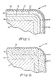
- FIGS 1 and 2 schematically illustrate typical coated articles 10 and 30 according to the invention.
- substrate 12 is a shaped cemented WC material, and may be a cutting tool or other article requiring wear resistance under the extreme conditions described above.
- a thin layer 14 of TiC covers the substrate, at least in the area subjected to wear.
- Composite layer 16 is deposited over TiC layer 14, and is made up of single-phase matrix portions 18 and 20 of Al2O3, and two-phase portions 22 of an Al2O3 matrix 24 and discrete particles 26 of ZrO2. As shown in Figure 1, there is no separation between the Al2O3 of matrix 24 of two-phase portions 22 and that of single-phase matrix portions 18 and 20.
- the Al2O3 of the composite coating is a single continuous matrix having a second phase of controlled composition and distribution dispersed therein.
- An outer layer 28 of TiN is deposited over the composite layer, giving article 10 a distinctive identifying color.
- FIG. 2 illustrates an alternate embodiment of the article according to the invention. Like features in the two figures are identified by the same reference numerals.
- substrate 12 is overlaid with thin TiC layer 14 in the same manner as shown in Figure 1.
- Composite layer 32 is deposited over TiC layer 14, and is made up of Al2O3 matrix 24 with particles 34 of Y2O3 stabilized ZrO2 evenly distributed throughout matrix 24.
- Outer layer 28 of TiN is deposited over the composite layer.
- samples of cutting tool inserts of a cemented carbide material, steel cutting grade C-5 were coated with a layer of TiC about 3 microns thick by known techniques in a CVD reactor.
- An excess of preweighed zirconium metal chips was placed in a separate vessel disposed in the reactor.
- An excess of aluminum chips was placed in a vessel outside the reactor.
- the reactor was evacuated to about 10 torr, then heated under low pressure, while being flushed with flowing hydrogen, to increase the outgassing before deposition.
- the reactor was cooled, at the deposition pressure and while being flushed with hydrogen, to about 300°C, then under ambient pressure and flowing nitrogen to room temperature.
- the deposition reaction conditions for Examples 1-6 are given in Table I, below.
- the halide gas was Cl2
- the carrier gas for the Al and Zr reactions was Ar
- the other reactant gas was CO2 with H2 as a carrier.
- the Cl2 flow rates were adjusted to give the metal chloride flow rates shown in Table I.
- the deposition pressure for Examples 1-6 was 50 torr; the temperature, 1040°C.
- a period of Al2O3 deposition (single-phase) ranging from 0.5 to 2.5 hrs was carried out before the two-phase Al2O3/ZrO2 deposition was begun.
- the single-phase deposition Ar gas was allowed to flow over the Zr, but the Cl2 gas flow was shut off.
- Example 1-6 The results of Examples 1-6 are shown in Table II.
- the thickness of the coatings was measured by the abrasive ball method (Calotest).
- the chemical composition of the coating was determined by x-ray diffraction analysis.
- the coating was deposited on the TiC underlayer as a stratified composite of alternating alumina and alumina/zirconia portions over a single-phase alumina portion, similar to that illustrated in Figure 1, but without the TiN layer over the oxide coating.
- the oxide coating and the TiC underlayer show satisfactory thickness and good adherence.
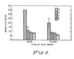
- Machining tests were performed on the coated cemented carbide cutting tool inserts samples of Example 6 (A) and, for comparison, on a ceramic based insert (B), and on two different commercial grades of TiC based inserts coated with Al2O3 (C and D).
- Inserts A, B, C and D were tested by turning a 4340 steel workpiece under dry conditions at 700 sfm, 0.01 ipr, 0.5 in DOC. For each insert, 28 cu. in. of metal were removed in 6.7 min cutting time. The results are illustrated in Fig. 3, showing the average nose and flank wear for each type of insert.
- the inserts coated by the method according to the invention compared favorably with the materials in current commercial use.
- Examples 1-6 The process of Examples 1-6 was repeated for Examples 7 and 8, to coat the same type of TiC coated cemented carbide cutting tool inserts, except that both AlCl3 and ZrCl4 were flowing during the entire deposition period.
- the deposition pressure and temperature were 50 torr and 1040°C respectively.
- the remaining reaction conditions are given in Table III below.
- the resulting composite coatings were similar to that illustrated in Figure 2, except that no TiN layer was deposited over the oxide coating.
- the coating was a continuous ZrO2 matrix with Al2O3 particles distributed therein. No single phase portion was deposited below the two phase portion of the oxide layer.
- Examples 1-8 are also useful for applying similar coatings to hard ceramic substrates to produce similar cutting inserts.
Landscapes
- Chemical & Material Sciences (AREA)
- Engineering & Computer Science (AREA)
- Ceramic Engineering (AREA)
- Materials Engineering (AREA)
- Organic Chemistry (AREA)
- Structural Engineering (AREA)
- Inorganic Chemistry (AREA)
- Mechanical Engineering (AREA)
- Chemical Kinetics & Catalysis (AREA)
- Metallurgy (AREA)
- Chemical Vapour Deposition (AREA)
- Organic Insulating Materials (AREA)
- Diaphragms For Electromechanical Transducers (AREA)
- Cutting Tools, Boring Holders, And Turrets (AREA)
- Organic Low-Molecular-Weight Compounds And Preparation Thereof (AREA)
- Other Surface Treatments For Metallic Materials (AREA)
- Laminated Bodies (AREA)
Abstract
Description
- This invention relates to an article comprising a wear resistant coating deposited on a cemented carbide or hard ceramic substrate, and more particularly to an article having a two or more phase composite oxide coating deposited on such a substrate.
- Cemented carbide and hard ceramic materials are known and are used extensively in such applications as mining tool bits, metal cutting and boring tools, metal drawing dies, wear-resistant machine parts and the like. Hard ceramic materials, as used herein refers to such compositions as Al₂O₃, Si₃N₄, silicon aluminum oxynitride and related compounds, as hard and dense monolithic or composite materials. The composites include those containing whiskers and/or particulates of SiC, Si₃N₄, other ceramic materials, and metal carbides, nitrides, and carbonitrides such as TiC and TiN. It is also known that the service properties such as wear, high temperature and chemical resistance of such materials may be enhanced by the application of one or more thin coatings of, for example, metal carbides, metal nitrides, or ceramics. Great strides have been made in improved performance of these coated substrates, for example in machining applications, by refinement of the substrate compositions and by applying various combinations of superimposed layers of coating materials. However, increasingly stringent use conditions, for example use at high cutting speeds or in extremely high temperatures and/or corrosive environments, are placing increasing demands upon the performance of such materials.
- The invention described herein and recited in the appended claims provides an article in which a wear resistant composite coating of controlled composition and distribution is deposited on a cemented carbide or hard ceramic substrate, the article showing improved abrasion resistance under extreme conditions of use.
- A wear resistant article according to the invention comprises a cemented carbide or hard ceramic substrate body having a fully dense, adherent, wear resistant, composite ceramic coating having at least two phases on the substrate. The coating comprises a continuous oxide layer about 0.1-20 microns thick of a material selected from the oxides of aluminum, zirconium, and yttrium. At least one discontinuous additional phase is dispersed as discrete particles within the oxide layer, the additional phase being of at least one material selected from the oxides of aluminum, zirconium, and yttrium, the material being different from that of the oxide layer.
- In the preferred article according to the invention, at least one intermediate layer is deposited between the substrate body and the composite ceramic layer. The intermediate layer is about 0.5-10 microns thick and is of one or more materials selected from the carbides, nitrides, and carbonitrides of Ti, Zr, Hf, Va, Nb, Ta, Cr, Mo, W, Si, and B. The additional phase may be evenly dispersed within the continuous oxide layer, or the composite ceramic layer may be a stratified layer,
- The invention will now be described in detail with reference to the accompanying drawings in which:
- FIGURES 1 and 2 are schematic cross-sectional representations of different embodiments of an article according to the invention.
- FIGURE 3 is a bar graph of comparative machining results.
- The article according to the present invention may be prepared by deposition of an adherent two or more phase composite oxide-based coating on a cemented metal carbide substrate, for example, a WC-Co or related material, or on a hard ceramic substrate for example a monolithic or composite alumina-, silicon nitride-, or silicon aluminum oxynitride-based material or related material. The deposition of a two or more phase oxide-based composite coating which is adherent to the substrate, wear resistant, high temperature resistant and resistant to chemical attack or breakdown at high temperatures depends on careful control of the process parameters. The outstanding properties of the coating are a result of the second phase of discrete particles of Al₂O₃, ZrO₂, or Y₂O₃, or a combination of these, within an Al₂O₃, ZrO₂, or Y₂O₃ matrix. For example, the preferred coatings include ZrO₂ particles and/or Y₂O₃ particles within a continuous Al₂O₃ matrix, Y₂O₃ particles within a continuous ZrO₂ matrix, ZrO₂ particles within a continuous Y₂O₃ matrix, or Y₂O₃ stabilized ZrO₂ particles, i.e. of an Y₂O₃-ZrO₂ solid solution, within a continuous Al₂O₃ matrix. The particles may be evenly distributed throughout the matrix, or their distribution may be controlled to achieve, for example, a stratified structure of single-phase oxide matrix portions alternating with two or more phase matrix/particle portions, preferably disposed at controlled intervals throughout the matrix. Similarly, the deposition may be controlled to deposit a single-phase continuous portion of controlled depth of the matrix material below the two or more phase portion of the coating.
- The preferred process for preparing the articles according to the invention involves the use of a mixture of gases including a mixture of metal halides and other reactant gases under carefully controlled conditions to deposit by chemical vapor deposition (CVD) compounds of the metals on a substrate. The preferred process involves passing over the substrate a first gaseous mixture of a first halide vapor selected from the halides of aluminum, yttrium and zirconium, with other reactant gases, and optionally a carrier gas. The temperature is about 900°-1250°C for cemented carbide substrates or about 900°-1500°C for hard ceramic substrates, and the pressure between about 1 torr and about ambient pressure. The partial pressure ratios, the flow rate, and the length of time is sufficient to deposit a continuous, fully dense, adherent, wear resistant layer of a material selected from the oxides of aluminum, zirconium, and yttrium about 0.1-20 microns thick on the substrate. At least one additional vapor selected from the halides of aluminum, zirconium, and yttrium is mixed with the first gaseous mixture. The additional metal halide vapor is different from the first halide vapor, and is mixed at a partial pressure selected to form at least one discontinuous additional phase, dispersed as discrete particles within the continuous oxide layer, of at least one material selected from the oxides of aluminum, zirconium, and yttrium, to form a wear resistant composite ceramic layer on the substrate. Alternatively, the article may be produced by appropriate physical vapor deposition (PVD) techniques.
- In the most preferred CVD process, the metal halides are produced by passing halide gas or gases over the metals, for example metal particulates. For example, the metals maybe combined as a mixture of metals, as a metal alloy, or as metal salts. A single halide gas is passed over the combined metals to form a mixture of metal halides. Alternatively, at least the metal forming the matrix is separate, and separate halide gas streams are passed over the metals to form separate metal halides, which are later combined. Carrier gases, for example Ar, may be combined with the halide gases. Preferred halide gases are Cl₂ and HCl, forming with the metals described above AlCl₃, and/or ZrCl₄, and/or YCl₃. These are combined with suitable other gases such as H₂ and CO₂ or other volatile oxidizing gases, such as H₂O.
- In order to achieve a first-phase matrix containing discrete particles of a second phase or phases, it is important to control the relative deposition by controlling such parameters as gas flow rates to produce the desired deposition of first and second phase materials.
- Further control over the deposition process may be achieved by pulsing the metal halide gas forming the second phase or phases while maintaining continuous flow of the metal halide gas forming the matrix. This pulsing method may also be used to control the distribution of the second phase within the matrix, for example to achieve either an even distribution or a stratified distribution as described above.
- Likewise, a single metal halide gas may be allowed to flow, with the other reactant gases, for a period of time sufficient to deposit a continuous single-phase portion of the material comprising the matrix, before the two-phase portion or alternating single-phase/two-phase portion of the coating is deposited.
- Some examples of composite coatings according to the invention are: Al₂O₃ matrix/ZrO₂ particles, ZrO₂ matrix/Y₂O₃ particles, Y₂O₃ matrix/ZrO₂ particles, Al₂O₃ matrix/Y₂O₃ stabilized ZrO₂ particles, Al₂O₃ matrix/Y₂O₃ particles, and Al₂O₃ matrix/ZrO₂ particles and Y₂O₃ particles.
- The terms second phase and two-phase as used herein refer to composites comprising a first phase, continuous oxide matrix compound and one or more additional or second phases which may be a single compound or more than one compound, in the form of discrete particles. The particles may be oxides of a single metal or a solid solution of oxides of more than one metal, and the individual particles maybe of the same or different compounds. The particles disclosed herein may be regularly shaped, as spheres, rods, whiskers, etc. or irregularly shaped.
- The composite coatings according to the invention are fully dense, adherent, and make it possible to combine the wear-resistant properties of two or more components without the problems associated with differences in expansion coefficients and adhesion presented by layering of continuous coatings of the materials.
- Further improvement in the adhesion of the coating to the substrate may be achieved by depositing between the composite coating and the substrate a thin intermediate layer of TiC, TiN, or other carbide, nitride or carbonitride of Ti, Zr, Hf, Va, Nb, Ta, Cr, Mo, W, Si or B. Such deposition may be achieved in known manner as a preliminary part of the same coating process or in a separate, prior coating process. Similarly, for special applications, for example friction, cosmetic, wear or thermal purposes, a thin outer layer such as TiN may be applied in known manner over the composite coating.
- Figures 1 and 2, not drawn to scale, schematically illustrate typical coated
articles substrate 12 is a shaped cemented WC material, and may be a cutting tool or other article requiring wear resistance under the extreme conditions described above. Athin layer 14 of TiC covers the substrate, at least in the area subjected to wear.Composite layer 16 is deposited overTiC layer 14, and is made up of single-phase matrix portions phase portions 22 of anAl₂O₃ matrix 24 anddiscrete particles 26 of ZrO₂. As shown in Figure 1, there is no separation between the Al₂O₃ ofmatrix 24 of two-phase portions 22 and that of single-phase matrix portions outer layer 28 of TiN is deposited over the composite layer, giving article 10 a distinctive identifying color. - Figure 2 illustrates an alternate embodiment of the article according to the invention. Like features in the two figures are identified by the same reference numerals. In Figure 2,
substrate 12 is overlaid withthin TiC layer 14 in the same manner as shown in Figure 1.Composite layer 32 is deposited overTiC layer 14, and is made up ofAl₂O₃ matrix 24 withparticles 34 of Y₂O₃ stabilized ZrO₂ evenly distributed throughoutmatrix 24.Outer layer 28 of TiN is deposited over the composite layer. - The following Examples are presented to enable those skilled in this art to more clearly understand and practice the present invention. These Examples should not be considered as a limitation upon the scope of the invention, but merely as being illustrative and representative thereof.
- After rinsing of all gas lines with their respective gases for 0.5-1 hr, samples of cutting tool inserts of a cemented carbide material, steel cutting grade C-5, were coated with a layer of TiC about 3 microns thick by known techniques in a CVD reactor. An excess of preweighed zirconium metal chips was placed in a separate vessel disposed in the reactor. An excess of aluminum chips was placed in a vessel outside the reactor. The reactor was evacuated to about 10 torr, then heated under low pressure, while being flushed with flowing hydrogen, to increase the outgassing before deposition. Following the deposition procedure, the reactor was cooled, at the deposition pressure and while being flushed with hydrogen, to about 300°C, then under ambient pressure and flowing nitrogen to room temperature.
- The deposition reaction conditions for Examples 1-6 are given in Table I, below. For all of these Examples the halide gas was Cl₂, the carrier gas for the Al and Zr reactions was Ar, and the other reactant gas was CO₂ with H₂ as a carrier. The Cl₂ flow rates were adjusted to give the metal chloride flow rates shown in Table I. The deposition pressure for Examples 1-6 was 50 torr; the temperature, 1040°C. For each of these Examples, a period of Al₂O₃ deposition (single-phase) ranging from 0.5 to 2.5 hrs was carried out before the two-phase Al₂O₃/ZrO₂ deposition was begun. During the single-phase deposition Ar gas was allowed to flow over the Zr, but the Cl₂ gas flow was shut off.

- The results of Examples 1-6 are shown in Table II. The thickness of the coatings was measured by the abrasive ball method (Calotest). The chemical composition of the coating was determined by x-ray diffraction analysis. The coating was deposited on the TiC underlayer as a stratified composite of alternating alumina and alumina/zirconia portions over a single-phase alumina portion, similar to that illustrated in Figure 1, but without the TiN layer over the oxide coating. The oxide coating and the TiC underlayer show satisfactory thickness and good adherence.

- Machining tests were performed on the coated cemented carbide cutting tool inserts samples of Example 6 (A) and, for comparison, on a ceramic based insert (B), and on two different commercial grades of TiC based inserts coated with Al₂O₃ (C and D).
- Inserts A, B, C and D were tested by turning a 4340 steel workpiece under dry conditions at 700 sfm, 0.01 ipr, 0.5 in DOC. For each insert, 28 cu. in. of metal were removed in 6.7 min cutting time. The results are illustrated in Fig. 3, showing the average nose and flank wear for each type of insert. The inserts coated by the method according to the invention compared favorably with the materials in current commercial use.
- The process of Examples 1-6 was repeated for Examples 7 and 8, to coat the same type of TiC coated cemented carbide cutting tool inserts, except that both AlCl₃ and ZrCl₄ were flowing during the entire deposition period. The deposition pressure and temperature were 50 torr and 1040°C respectively. The remaining reaction conditions are given in Table III below. The resulting composite coatings were similar to that illustrated in Figure 2, except that no TiN layer was deposited over the oxide coating. The coating was a continuous ZrO₂ matrix with Al₂O₃ particles distributed therein. No single phase portion was deposited below the two phase portion of the oxide layer.

- The processes described in Examples 1-8 are also useful for applying similar coatings to hard ceramic substrates to produce similar cutting inserts.
- While there has been shown and described what are at present considered the preferred embodiments of the invention, it will be obvious to those skilled in the art that various changes and modifications can be made therein without departing from the scope of the invention as defined in the appended claims.
Claims (15)
a cemented carbide or hard ceramic substrate body; and
a fully dense, adherent, wear resistant, composite ceramic coating having at least two phases on the substrate comprising:
a continuous oxide layer about 0.1-20 microns thick of a material selected from the group consisting of the oxides of aluminum, zirconium, and yttrium; and
at least one discontinuous additional phase dispersed as discrete particles within the oxide layer, of at least one material selected from the group consisting of oxides of aluminum, zirconium, and yttrium, the at least one material being different from that of the oxide layer.
Applications Claiming Priority (4)
| Application Number | Priority Date | Filing Date | Title |
|---|---|---|---|
| US5000 | 1987-01-20 | ||
| US07/004,999 US4701384A (en) | 1987-01-20 | 1987-01-20 | Composite coatings on cemented carbide substrates |
| US4999 | 1987-01-20 | ||
| US07/005,000 US4702970A (en) | 1987-01-20 | 1987-01-20 | Composite coatings on ceramic substrates |
Publications (4)
| Publication Number | Publication Date |
|---|---|
| EP0275977A2 true EP0275977A2 (en) | 1988-07-27 |
| EP0275977A3 EP0275977A3 (en) | 1990-05-02 |
| EP0275977B1 EP0275977B1 (en) | 1994-12-07 |
| EP0275977B2 EP0275977B2 (en) | 1998-08-19 |
Family
ID=26673765
Family Applications (1)
| Application Number | Title | Priority Date | Filing Date |
|---|---|---|---|
| EP88100690A Expired - Lifetime EP0275977B2 (en) | 1987-01-20 | 1988-01-19 | Composite coatings |
Country Status (7)
| Country | Link |
|---|---|
| EP (1) | EP0275977B2 (en) |
| JP (1) | JP2851279B2 (en) |
| AT (1) | ATE115194T1 (en) |
| AU (1) | AU1026588A (en) |
| BR (1) | BR8800223A (en) |
| CA (1) | CA1328580C (en) |
| DE (1) | DE3852322T3 (en) |
Cited By (4)
| Publication number | Priority date | Publication date | Assignee | Title |
|---|---|---|---|---|
| GB2246966A (en) * | 1990-08-13 | 1992-02-19 | Clive Durose Woodturners Limit | A machine tool |
| DE19828168A1 (en) * | 1998-06-24 | 1999-12-30 | Bosch Gmbh Robert | Applying ceramic layer onto ceramic green body for forming sliding-discharge spark plug |
| CN105102673A (en) * | 2013-03-21 | 2015-11-25 | 钴碳化钨硬质合金公司 | Coatings for cutting tools |
| CN114605173A (en) * | 2022-04-18 | 2022-06-10 | 中南大学 | Ablation-resistant and thermal shock-resistant zirconium silicate-high-alumina glass/HTBS high-entropy ceramic coating and preparation method and application thereof |
Families Citing this family (9)
| Publication number | Priority date | Publication date | Assignee | Title |
|---|---|---|---|---|
| DE10251404A1 (en) * | 2002-10-07 | 2004-04-15 | Widia Gmbh | Hard composite material for machine tool cutting tips, comprises body with multilayer coating comprising multi-phase- and single-phase layers of specified oxides |
| JP4888771B2 (en) * | 2006-11-17 | 2012-02-29 | 三菱マテリアル株式会社 | Surface coated cutting tool with excellent chipping resistance due to hard coating layer |
| JP4836202B2 (en) * | 2007-07-20 | 2011-12-14 | 日立ツール株式会社 | Coated tool |
| JP5240604B2 (en) * | 2008-04-18 | 2013-07-17 | 住友電工ハードメタル株式会社 | Surface coated cutting tool |
| JP5240605B2 (en) * | 2008-05-30 | 2013-07-17 | 住友電工ハードメタル株式会社 | Surface coated cutting tool |
| JP5286619B2 (en) * | 2008-08-01 | 2013-09-11 | 住友電工ハードメタル株式会社 | Surface coated cutting tool |
| JP5252276B2 (en) * | 2008-08-01 | 2013-07-31 | 住友電工ハードメタル株式会社 | Surface coated cutting tool |
| US9371580B2 (en) | 2013-03-21 | 2016-06-21 | Kennametal Inc. | Coated body wherein the coating scheme includes a coating layer of TiAl2O3 and method of making the same |
| US10273575B2 (en) * | 2016-08-31 | 2019-04-30 | Kennametal Inc. | Composite refractory coatings and applications thereof |
Family Cites Families (6)
| Publication number | Priority date | Publication date | Assignee | Title |
|---|---|---|---|---|
| CH540990A (en) * | 1971-07-07 | 1973-08-31 | Battelle Memorial Institute | Method for increasing the wear resistance of the surface of a cutting tool |
| US4052530A (en) * | 1976-08-09 | 1977-10-04 | Materials Technology Corporation | Co-deposited coating of aluminum oxide and titanium oxide and method of making same |
| SE406090B (en) * | 1977-06-09 | 1979-01-22 | Sandvik Ab | COATED HARD METAL BODY AND WAY TO PRODUCE A SUITABLE BODY |
| JPS5952954A (en) * | 1982-09-20 | 1984-03-27 | Nippon Telegr & Teleph Corp <Ntt> | System for communicating personal no. |
| JPS61201778A (en) * | 1985-03-01 | 1986-09-06 | Sumitomo Electric Ind Ltd | Coated sintered hard alloy |
| JPH0733578B2 (en) * | 1986-05-16 | 1995-04-12 | 住友電気工業株式会社 | Alumina-coated silicon nitride member |
-
1988
- 1988-01-14 AU AU10265/88A patent/AU1026588A/en not_active Abandoned
- 1988-01-14 CA CA000556547A patent/CA1328580C/en not_active Expired - Fee Related
- 1988-01-19 BR BR8800223A patent/BR8800223A/en unknown
- 1988-01-19 EP EP88100690A patent/EP0275977B2/en not_active Expired - Lifetime
- 1988-01-19 JP JP63007655A patent/JP2851279B2/en not_active Expired - Lifetime
- 1988-01-19 AT AT88100690T patent/ATE115194T1/en active
- 1988-01-19 DE DE3852322T patent/DE3852322T3/en not_active Expired - Fee Related
Non-Patent Citations (1)
| Title |
|---|
| None |
Cited By (6)
| Publication number | Priority date | Publication date | Assignee | Title |
|---|---|---|---|---|
| GB2246966A (en) * | 1990-08-13 | 1992-02-19 | Clive Durose Woodturners Limit | A machine tool |
| DE19828168A1 (en) * | 1998-06-24 | 1999-12-30 | Bosch Gmbh Robert | Applying ceramic layer onto ceramic green body for forming sliding-discharge spark plug |
| DE19828168C2 (en) * | 1998-06-24 | 2001-10-11 | Bosch Gmbh Robert | Process for producing a ceramic layer on a ceramic green body and use of the product thus obtained |
| CN105102673A (en) * | 2013-03-21 | 2015-11-25 | 钴碳化钨硬质合金公司 | Coatings for cutting tools |
| CN105102673B (en) * | 2013-03-21 | 2017-11-17 | 钴碳化钨硬质合金公司 | Coating for cutting element |
| CN114605173A (en) * | 2022-04-18 | 2022-06-10 | 中南大学 | Ablation-resistant and thermal shock-resistant zirconium silicate-high-alumina glass/HTBS high-entropy ceramic coating and preparation method and application thereof |
Also Published As
| Publication number | Publication date |
|---|---|
| AU1026588A (en) | 1988-07-21 |
| JPS63192869A (en) | 1988-08-10 |
| EP0275977A3 (en) | 1990-05-02 |
| BR8800223A (en) | 1988-08-30 |
| DE3852322D1 (en) | 1995-01-19 |
| DE3852322T3 (en) | 1998-12-03 |
| JP2851279B2 (en) | 1999-01-27 |
| DE3852322T2 (en) | 1995-04-27 |
| ATE115194T1 (en) | 1994-12-15 |
| EP0275977B1 (en) | 1994-12-07 |
| EP0275977B2 (en) | 1998-08-19 |
| CA1328580C (en) | 1994-04-19 |
Similar Documents
| Publication | Publication Date | Title |
|---|---|---|
| US4701384A (en) | Composite coatings on cemented carbide substrates | |
| US4745010A (en) | Process for depositing a composite ceramic coating on a cemented carbide substrate | |
| US4702970A (en) | Composite coatings on ceramic substrates | |
| US4965140A (en) | Composite coatings on refractory substrates | |
| US4749629A (en) | Ultrathin laminated oxide coatings and methods | |
| US4714660A (en) | Hard coatings with multiphase microstructures | |
| US5654035A (en) | Method of coating a body with an α-alumina coating | |
| US4950558A (en) | Oxidation resistant high temperature thermal cycling resistant coatings on silicon-based substrates and process for the production thereof | |
| US7011867B2 (en) | α-alumina coated cutting tool | |
| US5674564A (en) | Alumina-coated sintered body | |
| KR100348542B1 (en) | Oxide coated cutting tools | |
| US4525415A (en) | Sintered hard metal products having a multi-layer wear-resistant coating | |
| US4844951A (en) | Method for depositing ultrathin laminated oxide coatings | |
| EP0106817B1 (en) | Cutting insert and method of making the same | |
| CA1333763C (en) | Oxidation resistant, high temperature thermal cycling resistant coatings on silicon-based substrates and process for the production thereof | |
| US5035923A (en) | Process for the deposition of high temperature stress and oxidation resistant coatings on silicon-based substrates | |
| JPH0576546B2 (en) | ||
| US4943450A (en) | Method for depositing nitride-based composite coatings by CVD | |
| EP0275977B1 (en) | Composite coatings | |
| Prengel et al. | CVD coatings based on medium temperature CVD κ-and α-Al2O3 | |
| EP0275978B1 (en) | A method for depositing composite coatings | |
| JP3117978B2 (en) | Wear-resistant article and manufacturing method | |
| JP2646247B2 (en) | AlN coated silicon nitride based cutting tool | |
| JP4761291B2 (en) | Wear-resistant composite ceramic coating for cutting tools |
Legal Events
| Date | Code | Title | Description |
|---|---|---|---|
| PUAI | Public reference made under article 153(3) epc to a published international application that has entered the european phase |
Free format text: ORIGINAL CODE: 0009012 |
|
| AK | Designated contracting states |
Kind code of ref document: A2 Designated state(s): AT CH DE FR GB IT LI SE |
|
| PUAL | Search report despatched |
Free format text: ORIGINAL CODE: 0009013 |
|
| AK | Designated contracting states |
Kind code of ref document: A3 Designated state(s): AT CH DE FR GB IT LI SE |
|
| 17P | Request for examination filed |
Effective date: 19901009 |
|
| 17Q | First examination report despatched |
Effective date: 19920124 |
|
| RAP1 | Party data changed (applicant data changed or rights of an application transferred) |
Owner name: GTE VALENITE CORPORATION |
|
| RAP1 | Party data changed (applicant data changed or rights of an application transferred) |
Owner name: VALENITE INC. |
|
| GRAA | (expected) grant |
Free format text: ORIGINAL CODE: 0009210 |
|
| AK | Designated contracting states |
Kind code of ref document: B1 Designated state(s): AT CH DE FR GB IT LI SE |
|
| REF | Corresponds to: |
Ref document number: 115194 Country of ref document: AT Date of ref document: 19941215 Kind code of ref document: T |
|
| ET | Fr: translation filed | ||
| REF | Corresponds to: |
Ref document number: 3852322 Country of ref document: DE Date of ref document: 19950119 |
|
| ITF | It: translation for a ep patent filed | ||
| PLBI | Opposition filed |
Free format text: ORIGINAL CODE: 0009260 |
|
| 26 | Opposition filed |
Opponent name: SANDVIK AB Effective date: 19950907 |
|
| PLBF | Reply of patent proprietor to notice(s) of opposition |
Free format text: ORIGINAL CODE: EPIDOS OBSO |
|
| PLBF | Reply of patent proprietor to notice(s) of opposition |
Free format text: ORIGINAL CODE: EPIDOS OBSO |
|
| PLAW | Interlocutory decision in opposition |
Free format text: ORIGINAL CODE: EPIDOS IDOP |
|
| PLAW | Interlocutory decision in opposition |
Free format text: ORIGINAL CODE: EPIDOS IDOP |
|
| PUAH | Patent maintained in amended form |
Free format text: ORIGINAL CODE: 0009272 |
|
| STAA | Information on the status of an ep patent application or granted ep patent |
Free format text: STATUS: PATENT MAINTAINED AS AMENDED |
|
| 27A | Patent maintained in amended form |
Effective date: 19980819 |
|
| AK | Designated contracting states |
Kind code of ref document: B2 Designated state(s): AT CH DE FR GB IT LI SE |
|
| REG | Reference to a national code |
Ref country code: CH Ref legal event code: AEN Free format text: AUFRECHTERHALTUNG DES PATENTES IN GEAENDERTER FORM |
|
| ET3 | Fr: translation filed ** decision concerning opposition | ||
| PGFP | Annual fee paid to national office [announced via postgrant information from national office to epo] |
Ref country code: AT Payment date: 19990113 Year of fee payment: 12 |
|
| PGFP | Annual fee paid to national office [announced via postgrant information from national office to epo] |
Ref country code: GB Payment date: 19990121 Year of fee payment: 12 |
|
| PGFP | Annual fee paid to national office [announced via postgrant information from national office to epo] |
Ref country code: CH Payment date: 19990210 Year of fee payment: 12 |
|
| PG25 | Lapsed in a contracting state [announced via postgrant information from national office to epo] |
Ref country code: GB Free format text: LAPSE BECAUSE OF NON-PAYMENT OF DUE FEES Effective date: 20000119 Ref country code: AT Free format text: LAPSE BECAUSE OF NON-PAYMENT OF DUE FEES Effective date: 20000119 |
|
| PG25 | Lapsed in a contracting state [announced via postgrant information from national office to epo] |
Ref country code: LI Free format text: LAPSE BECAUSE OF NON-PAYMENT OF DUE FEES Effective date: 20000131 Ref country code: CH Free format text: LAPSE BECAUSE OF NON-PAYMENT OF DUE FEES Effective date: 20000131 |
|
| GBPC | Gb: european patent ceased through non-payment of renewal fee |
Effective date: 20000119 |
|
| REG | Reference to a national code |
Ref country code: CH Ref legal event code: PL |
|
| PGFP | Annual fee paid to national office [announced via postgrant information from national office to epo] |
Ref country code: FR Payment date: 20010102 Year of fee payment: 14 |
|
| PGFP | Annual fee paid to national office [announced via postgrant information from national office to epo] |
Ref country code: SE Payment date: 20010103 Year of fee payment: 14 Ref country code: DE Payment date: 20010103 Year of fee payment: 14 |
|
| PG25 | Lapsed in a contracting state [announced via postgrant information from national office to epo] |
Ref country code: SE Free format text: LAPSE BECAUSE OF NON-PAYMENT OF DUE FEES Effective date: 20020120 |
|
| PG25 | Lapsed in a contracting state [announced via postgrant information from national office to epo] |
Ref country code: DE Free format text: LAPSE BECAUSE OF NON-PAYMENT OF DUE FEES Effective date: 20020801 |
|
| EUG | Se: european patent has lapsed |
Ref document number: 88100690.2 |
|
| PG25 | Lapsed in a contracting state [announced via postgrant information from national office to epo] |
Ref country code: FR Free format text: LAPSE BECAUSE OF NON-PAYMENT OF DUE FEES Effective date: 20020930 |
|
| REG | Reference to a national code |
Ref country code: FR Ref legal event code: ST |
|
| PG25 | Lapsed in a contracting state [announced via postgrant information from national office to epo] |
Ref country code: IT Free format text: LAPSE BECAUSE OF NON-PAYMENT OF DUE FEES;WARNING: LAPSES OF ITALIAN PATENTS WITH EFFECTIVE DATE BEFORE 2007 MAY HAVE OCCURRED AT ANY TIME BEFORE 2007. THE CORRECT EFFECTIVE DATE MAY BE DIFFERENT FROM THE ONE RECORDED. Effective date: 20050119 |