EP0275438B1 - Method and apparatus for cooling in a float glass forming operation - Google Patents
Method and apparatus for cooling in a float glass forming operation Download PDFInfo
- Publication number
- EP0275438B1 EP0275438B1 EP87117923A EP87117923A EP0275438B1 EP 0275438 B1 EP0275438 B1 EP 0275438B1 EP 87117923 A EP87117923 A EP 87117923A EP 87117923 A EP87117923 A EP 87117923A EP 0275438 B1 EP0275438 B1 EP 0275438B1
- Authority
- EP
- European Patent Office
- Prior art keywords
- molten metal
- pool
- glass
- coolant
- conduit
- Prior art date
- Legal status (The legal status is an assumption and is not a legal conclusion. Google has not performed a legal analysis and makes no representation as to the accuracy of the status listed.)
- Expired
Links
- 238000001816 cooling Methods 0.000 title claims description 26
- 238000000034 method Methods 0.000 title claims description 7
- 239000005329 float glass Substances 0.000 title abstract description 5
- 238000007496 glass forming Methods 0.000 title abstract description 4
- 239000002184 metal Substances 0.000 claims abstract description 61
- 229910052751 metal Inorganic materials 0.000 claims abstract description 61
- 239000011521 glass Substances 0.000 claims abstract description 32
- 239000002826 coolant Substances 0.000 claims description 28
- ATJFFYVFTNAWJD-UHFFFAOYSA-N Tin Chemical compound [Sn] ATJFFYVFTNAWJD-UHFFFAOYSA-N 0.000 claims description 25
- 238000005086 pumping Methods 0.000 claims description 7
- 239000006060 molten glass Substances 0.000 claims description 6
- 239000005357 flat glass Substances 0.000 claims description 5
- 239000000203 mixture Substances 0.000 claims description 5
- 238000004891 communication Methods 0.000 claims description 2
- 238000007667 floating Methods 0.000 claims description 2
- 230000004888 barrier function Effects 0.000 claims 1
- OKTJSMMVPCPJKN-UHFFFAOYSA-N Carbon Chemical compound [C] OKTJSMMVPCPJKN-UHFFFAOYSA-N 0.000 description 7
- 229910002804 graphite Inorganic materials 0.000 description 5
- 239000010439 graphite Substances 0.000 description 5
- XLYOFNOQVPJJNP-UHFFFAOYSA-N water Substances O XLYOFNOQVPJJNP-UHFFFAOYSA-N 0.000 description 5
- 231100001261 hazardous Toxicity 0.000 description 3
- 230000003134 recirculating effect Effects 0.000 description 3
- 229910010271 silicon carbide Inorganic materials 0.000 description 3
- XEEYBQQBJWHFJM-UHFFFAOYSA-N Iron Chemical compound [Fe] XEEYBQQBJWHFJM-UHFFFAOYSA-N 0.000 description 2
- 229910052799 carbon Inorganic materials 0.000 description 2
- 230000000694 effects Effects 0.000 description 2
- HBMJWWWQQXIZIP-UHFFFAOYSA-N silicon carbide Chemical compound [Si+]#[C-] HBMJWWWQQXIZIP-UHFFFAOYSA-N 0.000 description 2
- RYGMFSIKBFXOCR-UHFFFAOYSA-N Copper Chemical compound [Cu] RYGMFSIKBFXOCR-UHFFFAOYSA-N 0.000 description 1
- 238000006124 Pilkington process Methods 0.000 description 1
- 239000000654 additive Substances 0.000 description 1
- 238000004873 anchoring Methods 0.000 description 1
- 230000002238 attenuated effect Effects 0.000 description 1
- 230000009286 beneficial effect Effects 0.000 description 1
- 230000015572 biosynthetic process Effects 0.000 description 1
- 238000005266 casting Methods 0.000 description 1
- 229910052802 copper Inorganic materials 0.000 description 1
- 239000010949 copper Substances 0.000 description 1
- 230000002939 deleterious effect Effects 0.000 description 1
- 238000000605 extraction Methods 0.000 description 1
- 239000012535 impurity Substances 0.000 description 1
- 229910052742 iron Inorganic materials 0.000 description 1
- 239000000463 material Substances 0.000 description 1
- 229910044991 metal oxide Inorganic materials 0.000 description 1
- 150000004706 metal oxides Chemical class 0.000 description 1
- 150000002739 metals Chemical class 0.000 description 1
- 238000000926 separation method Methods 0.000 description 1
- 229910052709 silver Inorganic materials 0.000 description 1
- 239000004332 silver Substances 0.000 description 1
- 229910001220 stainless steel Inorganic materials 0.000 description 1
- 239000010935 stainless steel Substances 0.000 description 1
- 239000000126 substance Substances 0.000 description 1
- 239000002470 thermal conductor Substances 0.000 description 1
- XOLBLPGZBRYERU-UHFFFAOYSA-N tin dioxide Chemical compound O=[Sn]=O XOLBLPGZBRYERU-UHFFFAOYSA-N 0.000 description 1
- 229910001887 tin oxide Inorganic materials 0.000 description 1
Images
Classifications
-
- C—CHEMISTRY; METALLURGY
- C03—GLASS; MINERAL OR SLAG WOOL
- C03B—MANUFACTURE, SHAPING, OR SUPPLEMENTARY PROCESSES
- C03B18/00—Shaping glass in contact with the surface of a liquid
- C03B18/02—Forming sheets
- C03B18/18—Controlling or regulating the temperature of the float bath; Composition or purification of the float bath
Definitions
- This invention relates to improvements in the process of forming flat glass by casting molten glass onto the surface of molten metal known as the float process.
- the molten metal is usually tin, sometimes with minor amounts of other elements such as iron or copper included, and other metals such as silver have been suggested as theoretically feasible.
- the temperature of the glass is relatively high, and as the glass progresses along the elongated forming chamber, its temperature is allowed to fall to a point where the viscosity is sufficient to permit removing the glass from the molten support and onto chemical conveying means. Therefore, removal of heat from the forming chamber is entailed and is conventionally performed by heat exchange means extended into the forming chamber above the glass. Proper control of the cooling is important in assuring the quality of the glass being produced.
- the water-cooled heat exchangers usually have the disadvantage of creating a sharp thermal gradient that may be deleterious to glass quality.
- the degree to which the metal can be cooled and the rate at which it can be circulated through the forming chamber are limited, thus restricting the rate of heat removal. Also, when tin is cooled, tin oxide tends to precipitate from the molten metal, which when reintroduced into the forming chamber can become deposited on the bottom surface of the glass ribbon, which is undesirable.
- Recirculating the molten metal is also shown in US-A-3,652,250 (Brichard) and 3,790,361 (Lawrenson). Both entail the problems of recirculating the molten metal noted above.
- US-A-4,197,106 shows a water-cooled pipe embedded in the bottom of the forming chamber or positioned in the pool of molten metal. It would have the disadvantages of inflexible cooling rate and a leak hazard as described above.
- This object is, according to the invention, attained by a method of forming glass wherein molten glass is passed onto a pool of molten metal in a forming chamber and is shaped into flat glass while floating on the molten metal pool, the glass loses heat to the surroundings in the forming chamber and heat is removed from the forming chamber, wherein at least a portion of that heat removal from the forming chamber is carried out by circulating coolant through a conduit in contact with the molten metal pool beneath the glass ribbon characterized in that a molten metal coolant is used which is substantially of the same composition as the molten metal pool.
- the invention also includes an apparatus for forming flat glass including forming a chamber adapted to hold a pool of molten metal, means to deliver molten glass onto the pool and cooling means comprised of a conduit in contact with the molten metal pool to convey coolant separately from the molten metal pool,pumping means being provided in communication with the conduit, characterized in that the pumping means are adapted to pump a molten metal coolant, which is substantially of the same composition as the molten metal pool.
- the pool of molten metal, and thus the underside of the glass ribbon, in a float forming chamber is cooled by using indirect heat exchange with a molten metal coolant compatible with but maintained separate from the main pool of molten metal.
- a molten metal coolant compatible with but maintained separate from the main pool of molten metal.
- Passages below the pool are provided for the coolant, and heat transfer takes place through the walls of the passages.
- the passages are fabricated from a relatively good thermal conductor such as graphite.
- the coolant is of substantially the same composition as the molten metal of the main pool so that any leakage from the coolant passages will not contaminate the pool or the glass, nor cause a hazardous reaction with the molten metal of the pool.
- the molten metal will be described as tin, but it should be understood that impurities or additives may be included and that the invention is not limited to any particular molten metal.
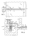
- FIG. 1 there is shown an intermediate portion of an elongated float glass forming chamber 10 comprised of a refractory basin 11 adapted to hold a pool of molten tin 12.
- a ribbon of glass 13 still in the plastic state, floats on the tin and is drawn longitudinally along the chamber as the glass is attenuated to a desired thickness.
- the glass progresses along the forming chamber, its temperature is permitted to fall, for example, from 1040°C (1900°F) to 600°C (1100°F).
- the tin maintained at temperatures substantially below that of the glass, serves to conduct heat away from the glass.
- a gathering chamber or sump 15 is appended to a side of the forming chamber basin 11 as shown in Figure 1 for holding a quantity of the coolant molten tin. Greater details of the sump 15 are shown in Figure 2.
- the sump may be comprised of a refractory basin 16 and a lid 17 and is adapted to hold a reservoir of molten tin 18.
- the sump is equipped with a pump for circulating the molten tin 18 through the cooling system.
- the pump may be comprised of a motor 20 on a bracket carried on the lid 17, a belt 22 driving a shaft 23, and an impeller 24 submerged in the tin 28 and driven by the shaft 23.
- the impeller may be supported from the lid 17 by a post 25.
- the impeller draws tin from the surrounding reservoir 18 and forces it through outlet pipe 26 and, by way of connecting pipes 27 and 28, to a cooling conduit 30 in the bottom of the forming chamber basin 11.
- the type of pump that may be employed for pumping molten tin is available commercially, such as Metaullics Pump Model D-12-C from Carborundum Co., Graphite Products Division, Solon, Ohio.
- the cooling conduit 30 extends transversely across the forming chamber in this embodiment, but it should be apparent that a wide variety of flow patterns could be employed. More than one conduit could extend from one sump, and a plurality of sumps may be employed.
- the conduit 30 includes an inlet passageway 31 and a return passageway 32 connected together at the far end by a cross bore 33.
- a short pipe 34 returns the tin to the reservoir 18.
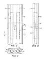
- the conduit 30 is preferably formed from an elongated block of graphite with the passages 31 and 32 bored therein. Depending upon the width of the forming chamber, the conduit may require two or more pieces of graphite spliced together. In the preferred embodiment the top of the conduit is flush with the interior bottom surface of the forming chamber.
- the cooling conduit could take the form of pipes submerged in the tin pool 12. Silicon carbide may be used as an alternative to graphite as a material for the conduit.
- FIG. 3 In the event that the conduit 30 is assembled from a plurality of pieces, a suitable joint arrangement is shown in Figures 3, 4, and 5.
- a ship-lapped joint is provided with upper and lower tabs 40 and 41 overlapping each other and a pin 42 extending through both pieces to bind them together.
- Sleeves 43 and 44 may be inserted in the passageways 31 and 32 spanning the joints so as to prevent leakage.
- the sleeves may be silicon carbide tubes.
- the cross-sectional shape of the cooling conduit shown in Figure 4 includes a widened bottom portion for the sake of securing the conduit against buoyant forces when it is cast into the forming chamber bottom.
- Other shapes and provisions for anchoring the conduit may be employed.
- the coller may be in the form of a simple hairpin shaped pipe cooler as shown in Figure 2 through which water is passed. Because of the low temperature of the water cooled pipe 35, it may be fabricated of stainless steel or the like. It is preferred to maintain the tin 18 in the sump at an approximately constant temperature during operation, and the rate of heat removal from the sump may be controlled by varying the depth to which the cooling pipe 35 is immersed in the tin. Although temperatures around 260°C (500°F) are theoretically feasible, it is preferred to maintain the coolant tin above 310°C (600°F) to assure that the tin does not solidify in any portion of the system.
- the rate of heat extraction from the forming chamber is controlled not only by the coolant tin temperature but also by the coolant flow rate. Both modes of control are advantageously versatile and easy to manipulate compared to prior art forming chamber cooling means.
- a beneficial cooling effect was established by pumping tin through the conduit arrangement shown in the drawings at a rate of approximately 1100 500 kilograms per minute (1100 pounds per minute) while the tin temperature in the sump was maintained at about 540°C (1000°F).
Landscapes
- Chemical & Material Sciences (AREA)
- Engineering & Computer Science (AREA)
- Materials Engineering (AREA)
- Organic Chemistry (AREA)
- Manufacture And Refinement Of Metals (AREA)
- Glass Compositions (AREA)
- Continuous Casting (AREA)
- Re-Forming, After-Treatment, Cutting And Transporting Of Glass Products (AREA)
- Glass Melting And Manufacturing (AREA)
- Manufacture, Treatment Of Glass Fibers (AREA)
Priority Applications (1)
| Application Number | Priority Date | Filing Date | Title |
|---|---|---|---|
| AT87117923T ATE61325T1 (de) | 1987-01-02 | 1987-12-04 | Verfahren und vorrichtung zum kuehlen beim herstellen von floatglas. |
Applications Claiming Priority (2)
| Application Number | Priority Date | Filing Date | Title |
|---|---|---|---|
| US07/000,028 US4741750A (en) | 1987-01-02 | 1987-01-02 | Method and apparatus for cooling in a float glass forming operation |
| US28 | 1987-01-02 |
Publications (2)
| Publication Number | Publication Date |
|---|---|
| EP0275438A1 EP0275438A1 (en) | 1988-07-27 |
| EP0275438B1 true EP0275438B1 (en) | 1991-03-06 |
Family
ID=21689568
Family Applications (1)
| Application Number | Title | Priority Date | Filing Date |
|---|---|---|---|
| EP87117923A Expired EP0275438B1 (en) | 1987-01-02 | 1987-12-04 | Method and apparatus for cooling in a float glass forming operation |
Country Status (9)
| Country | Link |
|---|---|
| US (1) | US4741750A (enExample) |
| EP (1) | EP0275438B1 (enExample) |
| JP (1) | JPS63185836A (enExample) |
| CN (1) | CN1009548B (enExample) |
| AT (1) | ATE61325T1 (enExample) |
| CA (1) | CA1287493C (enExample) |
| DE (1) | DE3768467D1 (enExample) |
| ES (1) | ES2020998B3 (enExample) |
| GR (1) | GR3001574T3 (enExample) |
Families Citing this family (4)
| Publication number | Priority date | Publication date | Assignee | Title |
|---|---|---|---|---|
| FR2865470B1 (fr) * | 2004-01-28 | 2007-08-10 | Saint Gobain | Verre plat par flottage sans point fixe |
| KR101412768B1 (ko) | 2011-01-24 | 2014-07-02 | 주식회사 엘지화학 | 유리판 제조 시스템의 플로트 배스 냉각 장치 및 방법 |
| CN103420564A (zh) * | 2012-05-23 | 2013-12-04 | 信义电子玻璃(芜湖)有限公司 | 锡液冷却器 |
| WO2018081664A1 (en) * | 2016-10-31 | 2018-05-03 | Corning Incorporated | Liquid metal viscosity control of molten glass |
Family Cites Families (7)
| Publication number | Priority date | Publication date | Assignee | Title |
|---|---|---|---|---|
| LU50237A1 (enExample) * | 1966-01-11 | 1967-07-11 | ||
| GB1289714A (enExample) * | 1969-09-05 | 1972-09-20 | ||
| GB1289715A (enExample) * | 1969-09-05 | 1972-09-20 | ||
| GB1314537A (en) * | 1970-09-23 | 1973-04-26 | Pilkington Brothers Ltd | Manufacture of flat glass by the float process |
| FR1205906A (fr) * | 1971-04-02 | 1960-02-05 | Glaces De Boussois | Perfectionnements à l'étirage continu du verre en feuille |
| US3928012A (en) * | 1973-03-06 | 1975-12-23 | Ppg Industries Inc | Method and apparatus for regulating the temperature of a glass sheet float tank |
| US4197106A (en) * | 1978-09-11 | 1980-04-08 | Ppg Industries, Inc. | Method and apparatus for asymmetric cooling in a glass sheet forming chamber |
-
1987
- 1987-01-02 US US07/000,028 patent/US4741750A/en not_active Expired - Fee Related
- 1987-12-04 ES ES87117923T patent/ES2020998B3/es not_active Expired - Lifetime
- 1987-12-04 AT AT87117923T patent/ATE61325T1/de not_active IP Right Cessation
- 1987-12-04 EP EP87117923A patent/EP0275438B1/en not_active Expired
- 1987-12-04 DE DE8787117923T patent/DE3768467D1/de not_active Expired - Lifetime
- 1987-12-08 CA CA000553798A patent/CA1287493C/en not_active Expired - Lifetime
- 1987-12-25 JP JP62329411A patent/JPS63185836A/ja active Granted
- 1987-12-28 CN CN87105974.6A patent/CN1009548B/zh not_active Expired
-
1991
- 1991-03-07 GR GR91400192T patent/GR3001574T3/el unknown
Also Published As
| Publication number | Publication date |
|---|---|
| JPS63185836A (ja) | 1988-08-01 |
| EP0275438A1 (en) | 1988-07-27 |
| CN87105974A (zh) | 1988-11-09 |
| GR3001574T3 (en) | 1992-11-23 |
| US4741750A (en) | 1988-05-03 |
| ATE61325T1 (de) | 1991-03-15 |
| CN1009548B (zh) | 1990-09-12 |
| DE3768467D1 (de) | 1991-04-11 |
| JPH0380739B2 (enExample) | 1991-12-25 |
| ES2020998B3 (es) | 1991-10-16 |
| CA1287493C (en) | 1991-08-13 |
Similar Documents
| Publication | Publication Date | Title |
|---|---|---|
| US11850657B2 (en) | System for melting solid metal | |
| EP0275438B1 (en) | Method and apparatus for cooling in a float glass forming operation | |
| US3393061A (en) | Method and apparatus for preventing bubbles in float glass apparatus | |
| US2192303A (en) | Apparatus for treating plated strip metal | |
| US3607199A (en) | Float glass apparatus with flow control dams | |
| US3520669A (en) | Method of and chamber for the manufacture of float glass | |
| US3938979A (en) | Method and apparatus for vertically drawing a glass ribbon | |
| US3941576A (en) | Method and apparatus for making molten glass with batch guiding means | |
| US4150714A (en) | Lead casting seal | |
| US3797555A (en) | Method for continuous casting of metal strips | |
| US4319904A (en) | Method and apparatus for guiding glass batch in a glass melting furnace | |
| US3652250A (en) | Apparatus for the treatment or production of flat glass floating on a liquid | |
| JPH11286761A (ja) | 溶融亜鉛系めっき装置及び方法 | |
| US3645713A (en) | Process for the treatment or production of floating flat glass | |
| EP0348227B1 (en) | Side wall construction for continuous belt caster | |
| CN209763742U (zh) | 一种具有撇渣器的感应炉 | |
| US3481728A (en) | Float glass chamber with separated temperature equalizing zones | |
| US4200143A (en) | Continuous horizontal caster | |
| JP5082157B2 (ja) | 亜鉛の鋳造装置及び鋳造方法、並びに亜鉛棒及び亜鉛棒の製造方法 | |
| EP0474956B1 (en) | Metallic vapor condenser capable of circulating a liquid metal | |
| JP2006083472A (ja) | 金属ストリップの連続溶融メッキのための溶融金属浮揚装置及び溶融金属浮揚方法 | |
| JPH05288478A (ja) | 水冷式銅樋の製造方法 | |
| US3182716A (en) | Apparatus for cooling molten metals | |
| NO132795B (enExample) | ||
| SU1087249A1 (ru) | Способ непрерывного лить чугуна |
Legal Events
| Date | Code | Title | Description |
|---|---|---|---|
| PUAI | Public reference made under article 153(3) epc to a published international application that has entered the european phase |
Free format text: ORIGINAL CODE: 0009012 |
|
| AK | Designated contracting states |
Kind code of ref document: A1 Designated state(s): AT BE CH DE ES FR GB GR IT LI LU NL SE |
|
| 17P | Request for examination filed |
Effective date: 19890117 |
|
| 17Q | First examination report despatched |
Effective date: 19890823 |
|
| GRAA | (expected) grant |
Free format text: ORIGINAL CODE: 0009210 |
|
| AK | Designated contracting states |
Kind code of ref document: B1 Designated state(s): AT BE CH DE ES FR GB GR IT LI LU NL SE |
|
| REF | Corresponds to: |
Ref document number: 61325 Country of ref document: AT Date of ref document: 19910315 Kind code of ref document: T |
|
| REF | Corresponds to: |
Ref document number: 3768467 Country of ref document: DE Date of ref document: 19910411 |
|
| ET | Fr: translation filed | ||
| ITF | It: translation for a ep patent filed | ||
| PLBE | No opposition filed within time limit |
Free format text: ORIGINAL CODE: 0009261 |
|
| STAA | Information on the status of an ep patent application or granted ep patent |
Free format text: STATUS: NO OPPOSITION FILED WITHIN TIME LIMIT |
|
| 26N | No opposition filed | ||
| REG | Reference to a national code |
Ref country code: GR Ref legal event code: FG4A Free format text: 3001574 |
|
| PGFP | Annual fee paid to national office [announced via postgrant information from national office to epo] |
Ref country code: SE Payment date: 19920907 Year of fee payment: 6 |
|
| PGFP | Annual fee paid to national office [announced via postgrant information from national office to epo] |
Ref country code: BE Payment date: 19920925 Year of fee payment: 6 |
|
| PGFP | Annual fee paid to national office [announced via postgrant information from national office to epo] |
Ref country code: AT Payment date: 19921012 Year of fee payment: 6 |
|
| PGFP | Annual fee paid to national office [announced via postgrant information from national office to epo] |
Ref country code: LU Payment date: 19921014 Year of fee payment: 6 |
|
| PGFP | Annual fee paid to national office [announced via postgrant information from national office to epo] |
Ref country code: GR Payment date: 19921029 Year of fee payment: 6 |
|
| PGFP | Annual fee paid to national office [announced via postgrant information from national office to epo] |
Ref country code: ES Payment date: 19921120 Year of fee payment: 6 |
|
| PG25 | Lapsed in a contracting state [announced via postgrant information from national office to epo] |
Ref country code: LU Free format text: LAPSE BECAUSE OF NON-PAYMENT OF DUE FEES Effective date: 19921204 |
|
| PGFP | Annual fee paid to national office [announced via postgrant information from national office to epo] |
Ref country code: CH Payment date: 19921230 Year of fee payment: 6 |
|
| PGFP | Annual fee paid to national office [announced via postgrant information from national office to epo] |
Ref country code: NL Payment date: 19921231 Year of fee payment: 6 |
|
| EPTA | Lu: last paid annual fee | ||
| PG25 | Lapsed in a contracting state [announced via postgrant information from national office to epo] |
Ref country code: AT Effective date: 19931204 |
|
| PG25 | Lapsed in a contracting state [announced via postgrant information from national office to epo] |
Ref country code: SE Effective date: 19931205 |
|
| PG25 | Lapsed in a contracting state [announced via postgrant information from national office to epo] |
Ref country code: LI Effective date: 19931231 Ref country code: CH Effective date: 19931231 Ref country code: BE Effective date: 19931231 |
|
| BERE | Be: lapsed |
Owner name: PPG INDUSTRIES INC. Effective date: 19931231 |
|
| PG25 | Lapsed in a contracting state [announced via postgrant information from national office to epo] |
Ref country code: GR Free format text: THE PATENT HAS BEEN ANNULLED BY A DECISION OF A NATIONAL AUTHORITY Effective date: 19940630 |
|
| PG25 | Lapsed in a contracting state [announced via postgrant information from national office to epo] |
Ref country code: NL Effective date: 19940701 |
|
| NLV4 | Nl: lapsed or anulled due to non-payment of the annual fee | ||
| REG | Reference to a national code |
Ref country code: CH Ref legal event code: PL |
|
| PG25 | Lapsed in a contracting state [announced via postgrant information from national office to epo] |
Ref country code: ES Free format text: LAPSE BECAUSE OF NON-PAYMENT OF DUE FEES Effective date: 19941205 |
|
| REG | Reference to a national code |
Ref country code: GR Ref legal event code: MM2A Free format text: 3001574 |
|
| EUG | Se: european patent has lapsed |
Ref document number: 87117923.0 Effective date: 19940710 |
|
| PGFP | Annual fee paid to national office [announced via postgrant information from national office to epo] |
Ref country code: FR Payment date: 19961115 Year of fee payment: 10 |
|
| PGFP | Annual fee paid to national office [announced via postgrant information from national office to epo] |
Ref country code: DE Payment date: 19961122 Year of fee payment: 10 |
|
| PGFP | Annual fee paid to national office [announced via postgrant information from national office to epo] |
Ref country code: GB Payment date: 19961128 Year of fee payment: 10 |
|
| PG25 | Lapsed in a contracting state [announced via postgrant information from national office to epo] |
Ref country code: GB Free format text: LAPSE BECAUSE OF NON-PAYMENT OF DUE FEES Effective date: 19971204 |
|
| PG25 | Lapsed in a contracting state [announced via postgrant information from national office to epo] |
Ref country code: FR Free format text: THE PATENT HAS BEEN ANNULLED BY A DECISION OF A NATIONAL AUTHORITY Effective date: 19971231 |
|
| GBPC | Gb: european patent ceased through non-payment of renewal fee |
Effective date: 19971204 |
|
| PG25 | Lapsed in a contracting state [announced via postgrant information from national office to epo] |
Ref country code: DE Free format text: LAPSE BECAUSE OF NON-PAYMENT OF DUE FEES Effective date: 19980901 |
|
| REG | Reference to a national code |
Ref country code: FR Ref legal event code: ST |
|
| REG | Reference to a national code |
Ref country code: ES Ref legal event code: FD2A Effective date: 19950112 |
|
| PG25 | Lapsed in a contracting state [announced via postgrant information from national office to epo] |
Ref country code: IT Free format text: LAPSE BECAUSE OF NON-PAYMENT OF DUE FEES;WARNING: LAPSES OF ITALIAN PATENTS WITH EFFECTIVE DATE BEFORE 2007 MAY HAVE OCCURRED AT ANY TIME BEFORE 2007. THE CORRECT EFFECTIVE DATE MAY BE DIFFERENT FROM THE ONE RECORDED. Effective date: 20051204 |