EP0275218A2 - Sich selbst unter Druck setzendes Sprühgerät - Google Patents
Sich selbst unter Druck setzendes Sprühgerät Download PDFInfo
- Publication number
- EP0275218A2 EP0275218A2 EP88300347A EP88300347A EP0275218A2 EP 0275218 A2 EP0275218 A2 EP 0275218A2 EP 88300347 A EP88300347 A EP 88300347A EP 88300347 A EP88300347 A EP 88300347A EP 0275218 A2 EP0275218 A2 EP 0275218A2
- Authority
- EP
- European Patent Office
- Prior art keywords
- receptacle
- liquid
- valve
- dispensing
- sprayer
- Prior art date
- Legal status (The legal status is an assumption and is not a legal conclusion. Google has not performed a legal analysis and makes no representation as to the accuracy of the status listed.)
- Ceased
Links
Images

Classifications
-
- B—PERFORMING OPERATIONS; TRANSPORTING
- B05—SPRAYING OR ATOMISING IN GENERAL; APPLYING FLUENT MATERIALS TO SURFACES, IN GENERAL
- B05B—SPRAYING APPARATUS; ATOMISING APPARATUS; NOZZLES
- B05B1/00—Nozzles, spray heads or other outlets, with or without auxiliary devices such as valves, heating means
- B05B1/02—Nozzles, spray heads or other outlets, with or without auxiliary devices such as valves, heating means designed to produce a jet, spray, or other discharge of particular shape or nature, e.g. in single drops, or having an outlet of particular shape
-
- B—PERFORMING OPERATIONS; TRANSPORTING
- B05—SPRAYING OR ATOMISING IN GENERAL; APPLYING FLUENT MATERIALS TO SURFACES, IN GENERAL
- B05B—SPRAYING APPARATUS; ATOMISING APPARATUS; NOZZLES
- B05B9/00—Spraying apparatus for discharge of liquids or other fluent material, without essentially mixing with gas or vapour
- B05B9/03—Spraying apparatus for discharge of liquids or other fluent material, without essentially mixing with gas or vapour characterised by means for supplying liquid or other fluent material
- B05B9/04—Spraying apparatus for discharge of liquids or other fluent material, without essentially mixing with gas or vapour characterised by means for supplying liquid or other fluent material with pressurised or compressible container; with pump
- B05B9/08—Apparatus to be carried on or by a person, e.g. of knapsack type
- B05B9/0805—Apparatus to be carried on or by a person, e.g. of knapsack type comprising a pressurised or compressible container for liquid or other fluent material
- B05B9/0811—Apparatus to be carried on or by a person, e.g. of knapsack type comprising a pressurised or compressible container for liquid or other fluent material comprising air supplying means actuated by the operator to pressurise or compress the container
- B05B9/0816—Apparatus to be carried on or by a person, e.g. of knapsack type comprising a pressurised or compressible container for liquid or other fluent material comprising air supplying means actuated by the operator to pressurise or compress the container the air supplying means being a manually actuated air pump
-
- B—PERFORMING OPERATIONS; TRANSPORTING
- B05—SPRAYING OR ATOMISING IN GENERAL; APPLYING FLUENT MATERIALS TO SURFACES, IN GENERAL
- B05B—SPRAYING APPARATUS; ATOMISING APPARATUS; NOZZLES
- B05B9/00—Spraying apparatus for discharge of liquids or other fluent material, without essentially mixing with gas or vapour
- B05B9/03—Spraying apparatus for discharge of liquids or other fluent material, without essentially mixing with gas or vapour characterised by means for supplying liquid or other fluent material
- B05B9/04—Spraying apparatus for discharge of liquids or other fluent material, without essentially mixing with gas or vapour characterised by means for supplying liquid or other fluent material with pressurised or compressible container; with pump
- B05B9/08—Apparatus to be carried on or by a person, e.g. of knapsack type
- B05B9/0805—Apparatus to be carried on or by a person, e.g. of knapsack type comprising a pressurised or compressible container for liquid or other fluent material
Definitions
- This invention relates to sprayers, particularly small, portable sprayers which are often used around homes or in light industrial applications.
- Such sprayers and liquid dispensers require manual pressurization before the liquid therein can be dispensed.
- the sprayer is pressurized by a hand pump prior to dispensing.
- Such hand pump pressurized sprayers have been the industry standard for small, portable sprayers for many, many years.
- a portable spray for dispensing liquids under pressure comprising a closed receptacle for containing liquids under pressure, the receptacle including a dispensing outlet operably connected to dispensing valve means which can be opened to dispense liquid under pressure or closed to seal the container is characterised by a one-way valve extending from outwardly of the receptacle to inside the receptacle, the one-way valve being adapted for connection to a source of liquid under pressure and comprising means for allowing entry of the liquid into the receptacle while preventing backflow out of the receptacle, whereby the receptacle is pressurized during entry of the liquid into the receptacle when the dispensing valve means is closed.
- a method of dispensing a liquid in a portable sprayer comprises the steps of: a) providing a portable receptacle having a dispensing outlet operably connected to dispensing valve means which can be opened to dispense liquid under pressure or closed to seal said receptacle, and a one-way valve; b) closing said dispensing valve means to entrap air within said receptacle; c) connecting said one-way valve to a source of liquid under pressure; d) introducing said liquid under pressure into said receptacle through said one-way valve whereby said entrapped air pressurizes said liquid within said receptacle; and e) dispensing said liquid through said receptacle dispensing outlet with said entrapped air constituting propellant means for dispensing said liquid.
- the sprayer of the present invention is fitted not only with valved dispensing means as is common for such sprayers, but also with a one-way valve adapted for connection to a pressurized source of the liquid to be dispensed from the sprayer.
- a hose connected to the building or home water system can be coupled to the one-way valve so that as the sprayer is filled with water, the pressure of the home or building system is conveyed to the sprayer itself.
- chemicals can be introduced into the sprayer ahead of the water or other diluent to be added under pressure so that a desired solution can be dispensed with the sprayer.
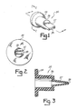
- a self-pressurizing sprayer 10 which includes a receptacle 12 formed of polyethylene or the like and a closure cap 14 which may be removably secured to receptacle 12 by threads 18.
- Cap 14 includes as an integral part thereof a spray nozzle 20 which communicates with the fluid contained in receptacle 12 and a trigger 22 which opeates a valve (not shown) to allow fluid under pressure to be dispensed through the nozzle.
- Receptacle 12 includes a filling check valve 24 mounted in receptacle sidewall 26.
- Check valve 24 prevents chemical solutions within receptacle 12 from backfilling into a hose or the like being used to fill receptacle 12 with liquid. This is particularly important where the liquid is water being supplied by the home water system.
- Receptacle 12 includes a mounting bracket 28 secured to the inner part of receptacle sidewall 26.
- a male quick connect coupler 30 of conventional construction is threadably secured to bracket 28 and sealed receptacle 12 against fluid leakage through check valve 24 to the outside.
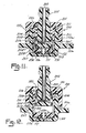
- a duck bill valve 32 seen in Figs. 1-3 is secured between bracket 28 and coupler 30 as shown in Figs. 4-7.
- Duck bill valve 32 is preferably a single piece one-way valve which includes a continuous base foot 34 and a body 36.
- Valve body 36 includes walls 37 of generally converging cross-sectional shape shown in Fig. 3 and terminates in a slit outlet 38. Because of the converging body walls 37, fluid under pressure may travel through slit outlet 38 only in the direction of arrow 40 but may not enter valve body 36 from the other direction.
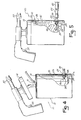
- Figs. 4-7 illustrate the sprayer in use.
- closure cap 14 is removed and receptacle 12 filled with a quantity of a substance such as concentrated liquid or solid powdered chemicals 37a (Fig. 4).
- Receptacle sidewall 26 may include indicator lines (not shown) to inform the user when the correct level has been reached.
- Clsoure cap 14 is then sealed, and a hose 42 is connected for delivery of diluent (in this case water) to receptacle 12 by a female quick connect coupler 44 which is snap-fitted over male quick connect coupler 30.
- Fluid under pressure is charged through hose 42 and through one-way valve 32 (Fig. 5) into receptacle 12, and compresses the air 39 which previously occupied the receptacle.
- hose 42 is disconnected (Fig. 6) from the receptacle 12.
- sprayer 10 may then be utilized to deliver the fluid 41 in receptacle 12 under pressure to an outside source with the compressed air in the receptacle acting as the propellant.
- Receptacle 12 or closure cap 14 may include a closable port (not shown) for recharging the fluid in the receptacle when the compressed air propellant is exhausted.
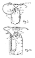
- the alternative embodiment sprayer 100 (Fig. 8) is of a somewhat larger, though still portable, variety. It comprises a moulded plastic container 101, preferably moulded of polyethylene, which includes an integrally moulded, threaded valve seat 102 for receiving a one-way valve assembly including one-way valve 110 an a quick disconnect hose coupler 120 (Figs. 8 and 9). Container 101 also includes an integrally moulded outlet fitting 103 to which delivery tube 130 is secured and an integrally moulded threaded top opening 104 upon which the closure and hand pump assembly 150 is threadably mounted (Figs. 8 and 10).
- One-way valve 110 is made of a flexible rubber and comprises an annular shoulder 111 which surrounds and projects radially outwardly from a central, cylindrical body 112. Cylindrical body 112 projects in one direction away from shoulder 111 defining a relatively large inlet opening and then terminates in a duck bill flap arrangement 113 at approximately its juncture with that side of annular shoulder 111 from which it projects. Duck bill flaps 113 define a slit opening 114 therebetween where they come together. The cross section of converging flexible rubber walls 113 is sufficiently thin that they will flex apart slightly to allow fluid to flow therethrough in one direction, but will be compressed together so as to close slit 114 under back pressure within container 101. There is an annular recess 115 in shoulder 110 which surrounds duck bill flaps 113, thereby giving them additional flexibility for proper closure against the movement of fluids in the wrong direction through slit opening 114.
- Duck bill valve 110 is seated within the recess defined by valve seat 102 and is held in position by threading hose coupler 120 into the integrally formed threads in valve seat 102.
- the threaded, cylindrical end 121 of quick disconnect hose coupling 120 seats on top of shoulder 111 of valve 110 and thereby traps it in position against the base wall of valve seat 102.
- Quick disconnect hose coupler 120 is of a conventional quick disconnect configuration. It is adapted for quick disconnect mating to a quick disconnect coupler 125 which can be threaded onto the end of a conventional garden hose or the like 126 (Fig. 10).
- one-way valve 110 and hose coupler assembly 120 are positioned in the top wall 101a of container 101. This makes it easier to connect hose 126 via coupling 125 in that one can press downwardly against coupler 120 while container 101 is resting on the ground or other firm surface. If coupler 120 were located in the side of container 101, the user would have to hold container 101 against movement while pressing hose 126 and coupling 125 onto coupler 120.
- the alternative embodiment sprayer 100 is conventional.
- the flexible delivery tube 130 is clamped over the integrally moulded outlet fitting 103 by means of a tube clamp 131.
- the other end of flexible deliver tube 130 is secured to a spray wand 140 which includes a spray nozle 141 at one end and a valve assembly 142 at the other end.
- the hand pump assembly 150 includes a threaded closure 151 and is threaded over the threaded top opening 104 of container 101.
- a pump handle 152 includes an elongated groove integrally formed therein so that the wand 140 can be seated in the groove for storage and transport. The handle 152 can be released for pumping to facilitate hand pressurization of container 101, or it can be locked in a down position to serve as a carrying handle for sprayer 100. Sprayer 100 can also be carried by the user over his shoulder by means of a carrying strap 160 suitable fastened to container 101.
- the hand pump assembly 150 serves not only as a closure for receptacle 101, but also makes it possible to repressurize receptacle 101 when the user is remote from the source of liquid under pressure which is being used. Thus a homeowner spraying chemicals on his lawn might be at a remote location from the hose and still have some chemical solution remaining in container 101. He can simply use hand pump 150 to repressurize receptacle 101 and finish using the solution therewithin.
- Coupler 125 is preferably of the conventional type which automatically allows the fluid under pressure to pass when it is coupled to coupling 120. If the fluid is water and one desires to spray a solution of chemicals, the chemicals are first introduced into container 101 through top opening 104 by simply unthreading top closure 151 and removing pump/handle assembly 150. With the solid or liquid chemicals introduced into container 101, closure 151 is again threaded onto threaded top opening 104 and hose 126 is coupled as described above.
- container 101 will be filled with water coupled to a house or industrial water system.
- the pressure of such water is a fairly predictable 415 to 485 kPa (60 to 70 psi).
- automatic shut off valve assembly 200 is provided (Fig. 11 an 12) in place of one-way valve 110 and hose coupler 120.
- the integrally moulded valve seat 102 of container 101 does not include internal threads. Rather, it includes an upwardly projecting, integrally moulded sleeve 102a having integrally moulded external threads upon which can be threaded a valve closure cap 201.
- Valve closure cap 201 includes a central opening which telescopingly receives a hose coupling stem 202, which includes a central fluid flow passage 203. Passage 203 terminates at the bottom in a lateral passage 204 which in turn feeds into an annular passage 205 around the base of coupling stem 202. Annular passage 205 is defined by a pair of annular shoulders 206, 207 projecting from the base of coupling stem 202 on either side of annular passage 205. Each annular shoulder 206 and 207 includes a groove formed therein for receiving top and bottom O rings 208 and 209 respectively.
- a sleeve 210 Positioned between telescoping coupling stem 202 and the interior wall of externally threaded sleeve 102a is a sleeve 210 having an outwardly radiating top flange 211 which seats on the top edge of threaded sleeve 102a and is held in place by top threaded closure 201.
- Sleeve 210 includes a plurality of vertical grooves or passages 212 which extend from the bottom of sleeve 210 upwardly a portion of the distance towards the top thereof. When telescoping coupling 202 is in the position shown in Fig. 11, annular passage 205 is in flow communication with vertical groove passages 212.
- a one-way duck bill valve 110a which is very similar to duck bill valve 110 previously described.
- One-way duck bill valve 110a is held in position by means of a washer 230 seated over shoulder flange 111 of valve 110a and held down by the lower terminal end of sleeve 210.
- Washer 230 includes upwardly projecting dimples 231 which insure that there will be a fluid flow passage between the bottom of telescoping stem 202 an the top of washer 230 even when telescoping stem 202 is in its bottom most position as shown in Fig. 11, thereby allowing fluid to flow over washer 230 and into the opened top of duck bill valve 110a.
- Coupling stem 202 is biased downwardly into the position illustrated in Fig. 11 by means of a coil spring 220 extending between the undersurface of the top of closure 201 and the upper surface of upper annular shoulder 206.
- stem 202 is forced upwardly until, when it is in the position illustrated in Fig. 12, annular passage 205 is sealed from vertical groove passages 212 by means of the bottom O ring 209 in bottom annular shoulder 207. This prevents any further flow of fluid into container 101 and prevents container 101 from being over pressurized.
- coil spring 220 will be selected such that a back pressure of between 415 and 485 kPa (70 and 80 pounds) will close valve assembly 200 and prevent further pressurization of container 101.
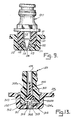
- Fig. 13 illustrates a one-way valve alternative to the use of duck bill valve 110 or 110a.
- duck bill valve 110 is replaced by a poppet valve 300 combined with a flow maintaining valve stop 310.
- Poppet valve 200 is axially movably received within the internal passage 124 of hose coupler 120 and flow maintaining valve stop 310 is held in place in the base of valve seat 102 by hose coupling 120 being threaded into valve seat 102 over valve stop 310.
- Poppet 300 includes a stem 301 comprised of intersecting flanges, giving it an "X" shaped cross section which keeps poppet 300 properly orientated as it moves within passage 124, but still allows water to flow around stem 301. It is made of rubber with a Shore A durometer of 65-90, preferably 80 ⁇ 5.
- Stem 301 is connected to the valve head 302 which includes a cone shaped upper surface 302 defining a valve seat.
- Head 302 is larger in diameter than the base of passageway 124 so that it seats on the base of passage 124 and blocks the flow of liquid or air therethrough.
- passage 124 opens into a larger chamber 124a at the base of hose coupler 120.
- Poppet head 302 is larger in diameter than passage 124, but is not as large in diameter as the internal diameter of chamber 124a.
- Ribs 303 project radially from the perimeter of head 302 to help keep poppet 300 centred by their engagement with the walls of chamber 124a, without blocking the flow of fluid around head 302.
- Head 302 includes a flat bottom 302b which, when one connects hose coupler 120 to a source of fluid under pressure, gets forced down and seats on top of valve stop 310.
- Valve stop 310 comprises basically a shoulder washer having an annular projecting shoulder 311 projecting radially from a main cylindrical body 312 which includes a central opening 313 extending therethrough in alignment with the opening in the base of valve seat 102.
- a plurality of radial channels 314 are cut into the top of the main cylindrical body 312 and communicate with central opening 313 so that even when the bottom 302b of valve head 302 is seated on top of valve stop 310, water can flow around valve head 302, past radiating ribs 303, through channels 314 and into passageway 313, thereby allowing fluid to flow into the interior of container 101.
- container 101 is pressurized and the source of pressurized fluid is uncoupled from hose coupler 120, pressure within container 101 will push poppet 300 upwardly so that the conical upper surface 302a of its head 302 seats against the base of coupler passageway 124, thereby preventing the flow of air or liquid back around valve head 302 to the exterior of container 101.
Landscapes
- Containers And Packaging Bodies Having A Special Means To Remove Contents (AREA)
- Nozzles (AREA)
Applications Claiming Priority (4)
| Application Number | Priority Date | Filing Date | Title |
|---|---|---|---|
| US346987A | 1987-01-15 | 1987-01-15 | |
| US07/058,519 US4782982A (en) | 1987-01-15 | 1987-06-05 | Self-pressurizing sprayer |
| US58519 | 1987-06-05 | ||
| US3469 | 1995-09-08 |
Publications (2)
| Publication Number | Publication Date |
|---|---|
| EP0275218A2 true EP0275218A2 (de) | 1988-07-20 |
| EP0275218A3 EP0275218A3 (de) | 1990-02-28 |
Family
ID=26671788
Family Applications (1)
| Application Number | Title | Priority Date | Filing Date |
|---|---|---|---|
| EP88300347A Ceased EP0275218A3 (de) | 1987-01-15 | 1988-01-15 | Sich selbst unter Druck setzendes Sprühgerät |
Country Status (5)
| Country | Link |
|---|---|
| US (1) | US4782982A (de) |
| EP (1) | EP0275218A3 (de) |
| KR (1) | KR890000159A (de) |
| AU (1) | AU602605B2 (de) |
| CA (1) | CA1319914C (de) |
Cited By (4)
| Publication number | Priority date | Publication date | Assignee | Title |
|---|---|---|---|---|
| WO1997038795A1 (en) * | 1994-10-24 | 1997-10-23 | Mischa Stahlhammer | Chargeable handsprayer |
| US7363673B2 (en) | 2003-02-13 | 2008-04-29 | Black & Decker Inc. | Hand held scrubbing tool |
| US7414337B2 (en) | 2005-03-14 | 2008-08-19 | Black & Decker Inc. | Scrubber |
| US7937792B2 (en) | 2006-10-19 | 2011-05-10 | Black & Decker Inc. | Pole scrubber |
Families Citing this family (38)
| Publication number | Priority date | Publication date | Assignee | Title |
|---|---|---|---|---|
| US4930664A (en) * | 1987-01-15 | 1990-06-05 | Root-Lowell Manufacturing Company | Self-pressurizing sprayer |
| US5072884A (en) * | 1989-08-11 | 1991-12-17 | Root-Lowell Corporation | Elliptical tank portable garden sprayer |
| US5186391A (en) * | 1989-10-06 | 1993-02-16 | Wallace Roueche | Portable sprayer |
| US5358150A (en) * | 1990-07-03 | 1994-10-25 | Mpl Technologies, Inc. | Pressurized fluid dispensing device |
| US5373975A (en) * | 1992-07-30 | 1994-12-20 | Husted; Royce H. | Water gun |
| US5284300A (en) * | 1992-08-19 | 1994-02-08 | Jon Brown | Portable spray system |
| US5366108A (en) * | 1992-08-20 | 1994-11-22 | Michael Darling | Toy water gun system |
| US5597095A (en) * | 1993-06-09 | 1997-01-28 | Precision Valve Corporation | Dual arm aerosol actuator having a movable and stationary arm |
| US5586695A (en) * | 1993-10-07 | 1996-12-24 | Labus; Rainer H. | Sprayed liquid dispensing apparatus |
| USD357177S (en) | 1993-10-07 | 1995-04-11 | Labus Rainer H | Refillable pressure can for cleaning solvents |
| US5656035A (en) * | 1995-04-25 | 1997-08-12 | Avoy; Donald R. | Refillable fibrinogen dispensing kit |
| US5673731A (en) * | 1996-05-03 | 1997-10-07 | Morton International, Inc. | Method and apparatus for filling elongated pressurized fluid containers from the side |
| US6145711A (en) * | 1997-04-24 | 2000-11-14 | Black & Decker Inc. | Portable sprayer with power pump |
| US6125879A (en) * | 1997-08-20 | 2000-10-03 | Black & Decker Inc. | Release mechanism for a battery powered wheeled garden sprayer |
| US5924633A (en) * | 1997-10-24 | 1999-07-20 | H.D. Hudson Manufacturing Company | Sprayer tank with internal threads and swivel hose outlet |
| AU4420899A (en) * | 1998-06-03 | 1999-12-20 | R. J. Louis | Self-contained misting device |
| US7191962B2 (en) * | 2000-08-22 | 2007-03-20 | Chapin Manufacturing, Inc. | Sprayer apparatus with backflow valve |
| US6695228B2 (en) | 2000-08-22 | 2004-02-24 | Chapin Manufacturing, Inc. | Self-pressurizing sprayer |
| US6715643B1 (en) | 2001-03-28 | 2004-04-06 | J. Keith Kelly | Device and method for dispensing chemical product |
| AU2003285894A1 (en) * | 2002-10-18 | 2004-05-04 | Pall Corporation | Multiple well device |
| US20040261902A1 (en) * | 2003-02-10 | 2004-12-30 | Hasbro, Inc. | Quick fill cap for a toy water gun |
| US20060261186A1 (en) * | 2005-03-16 | 2006-11-23 | Fontaine James R | Hand-portable pressurized sprayer apparatus provided with safety valve |
| US7434749B2 (en) * | 2005-12-13 | 2008-10-14 | Scott Wu | Sprayer |
| KR20080037196A (ko) * | 2006-10-25 | 2008-04-30 | 변영광 | 튜브형 화장품용기용 체크밸브의 구조 |
| KR100858320B1 (ko) * | 2007-02-14 | 2008-09-17 | 박영주 | 유체용기 |
| US20100019062A1 (en) * | 2008-07-23 | 2010-01-28 | Root-Lowell Manufacturing Company | Tank sprayer with separate concentrate container |
| US20110202019A1 (en) * | 2009-12-04 | 2011-08-18 | Mt Industries, Inc. | Hand held skin treatment spray system with air heating element |
| US20120056017A1 (en) * | 2009-12-04 | 2012-03-08 | Scott Thomason | Spray Gun Tank Configurations |
| US9038923B2 (en) | 2010-04-05 | 2015-05-26 | Wagner Spray Tech Corporation | Fluid level indicator in an airless fluid sprayer |
| US8919669B2 (en) * | 2010-04-05 | 2014-12-30 | Wagner Spray Tech Corporation | Fluid intake assembly for remote fluid source |
| US9604236B2 (en) | 2010-04-05 | 2017-03-28 | Jeffrey E. Sandahl | Fluid intake assembly for a fluid sprayer |
| FR2973787B1 (fr) * | 2011-04-11 | 2013-03-29 | Rexam Dispensing Sys | Flacon de distribution d'un produit fluide equipe d'une soupape de remplissage |
| USD679940S1 (en) | 2011-08-16 | 2013-04-16 | Glenn B. Paige | Fill cap for a drink container |
| US8931522B2 (en) * | 2011-08-16 | 2015-01-13 | Glenn B. Paige | Fill cap for a drink container |
| US8757446B1 (en) * | 2013-01-10 | 2014-06-24 | Cosda Manu Facturing Company | Fluid supplying device |
| WO2014164770A1 (en) * | 2013-03-11 | 2014-10-09 | OutSol Inc. | Portable self-pressurizing spray system |
| US9770732B2 (en) * | 2013-03-11 | 2017-09-26 | Outsol, Llc | Portable spray system |
| WO2022192293A1 (en) * | 2021-03-08 | 2022-09-15 | Gojo Industries, Inc. | Trigger sprayer with refill port |
Family Cites Families (15)
| Publication number | Priority date | Publication date | Assignee | Title |
|---|---|---|---|---|
| US194597A (en) * | 1877-08-28 | Improvement in hydro-pneumatic fire-extinguishers | ||
| US1078028A (en) * | 1911-04-28 | 1913-11-11 | Harold Roscoe Zeamans | Liquid-dispensing device. |
| US1246227A (en) * | 1917-05-09 | 1917-11-13 | Nya Aktiebolaget Terracotta | Apparatus for preparing and distributing of aerated drinks or similar fluids. |
| US1299567A (en) * | 1918-01-21 | 1919-04-08 | Hydraulic Oil Systems Corp | Hydraulic storage and delivery system. |
| US2501260A (en) * | 1946-03-02 | 1950-03-21 | Brodin Arivd | Fertilizer mixer and dispenser |
| US2645381A (en) * | 1948-03-08 | 1953-07-14 | Charles W Lattman | Portable dispensing tank |
| US2750752A (en) * | 1953-11-23 | 1956-06-19 | Western Electric Co | Liquid dispensing device |
| US3109566A (en) * | 1962-12-03 | 1963-11-05 | Crown Ind Products Company | Spray valve structure |
| US3245583A (en) * | 1964-02-11 | 1966-04-12 | Reynolds Metals Co | Gas charging and liquid dispensing apparatus and method |
| CH418051A (de) * | 1964-10-07 | 1966-07-31 | Brugger Paul | Spritze für landwirtschaftliche Zwecke, insbesondere Baum- oder Rebenspritze, für Handbedienung |
| DE1961486A1 (de) * | 1969-12-08 | 1971-06-09 | Grothoff Geb Zweifel | Nachfuellbarer Behaelter zur Herstellung und Entnahme eines verspruehbaren Treibgas-Fluessigkeits-Gemisches |
| US3790039A (en) * | 1972-12-29 | 1974-02-05 | H Zucconi | Keg tapping assembly |
| DE3022913A1 (de) * | 1980-06-19 | 1981-12-24 | Alfred Dipl.-Volksw. 8135 Söcking Becker | Zerstaeubereinrichtung |
| US4431117A (en) * | 1981-12-09 | 1984-02-14 | Robertshaw Controls Company | Propellant storage construction, parts therefor and methods of making the same |
| US4509664A (en) * | 1983-03-23 | 1985-04-09 | H. D. Hudson Manufacturing Company | Portable sprayer with safety cover |
-
1987
- 1987-06-05 US US07/058,519 patent/US4782982A/en not_active Expired - Lifetime
-
1988
- 1988-01-13 CA CA000556412A patent/CA1319914C/en not_active Expired - Lifetime
- 1988-01-14 KR KR1019880000212A patent/KR890000159A/ko not_active Ceased
- 1988-01-15 EP EP88300347A patent/EP0275218A3/de not_active Ceased
- 1988-08-24 AU AU21513/88A patent/AU602605B2/en not_active Expired
Cited By (6)
| Publication number | Priority date | Publication date | Assignee | Title |
|---|---|---|---|---|
| WO1997038795A1 (en) * | 1994-10-24 | 1997-10-23 | Mischa Stahlhammer | Chargeable handsprayer |
| US7363673B2 (en) | 2003-02-13 | 2008-04-29 | Black & Decker Inc. | Hand held scrubbing tool |
| US7707674B2 (en) | 2003-02-13 | 2010-05-04 | Black & Decker Inc. | Hand held scrubbing tool |
| US7414337B2 (en) | 2005-03-14 | 2008-08-19 | Black & Decker Inc. | Scrubber |
| US7818864B2 (en) | 2005-03-14 | 2010-10-26 | Black & Decker Inc. | Scrubber |
| US7937792B2 (en) | 2006-10-19 | 2011-05-10 | Black & Decker Inc. | Pole scrubber |
Also Published As
| Publication number | Publication date |
|---|---|
| US4782982A (en) | 1988-11-08 |
| AU2151388A (en) | 1990-03-01 |
| EP0275218A3 (de) | 1990-02-28 |
| CA1319914C (en) | 1993-07-06 |
| AU602605B2 (en) | 1990-10-18 |
| KR890000159A (ko) | 1989-03-13 |
Similar Documents
| Publication | Publication Date | Title |
|---|---|---|
| EP0275218A2 (de) | Sich selbst unter Druck setzendes Sprühgerät | |
| US4930664A (en) | Self-pressurizing sprayer | |
| US6695228B2 (en) | Self-pressurizing sprayer | |
| US6554319B2 (en) | Trigger sprayer dispensing system | |
| US6619318B2 (en) | Multiple flow rate eductive dispenser | |
| RU2127157C1 (ru) | Система распыления | |
| EP0238611B1 (de) | Zerstäuber für einen behälter zum versprühen einer flüssigkeit | |
| US5439141A (en) | Dual liquid spraying system | |
| EP0582701A1 (de) | Flüssigkeitsspendereinrichtung mit adapter. | |
| US6056167A (en) | Pressure sprayer | |
| US20080105763A1 (en) | Device for attaching a dip tube to a fluid container | |
| US5465875A (en) | Closed transfer devices for agricultural chemicals and the like | |
| IL98299A (en) | A system for issuing and hermetically diluting a concentrated chemical | |
| US20100019062A1 (en) | Tank sprayer with separate concentrate container | |
| US5474210A (en) | Fluid dispensing device | |
| EP1723071B1 (de) | Zerstäuber vom triggertyp mit sicherer zuführungsrohrverbindung | |
| EP0558546B1 (de) | Versorgungskappen für behälter | |
| US6394148B1 (en) | Pump connection | |
| JPS63190670A (ja) | 自巳加圧式噴務器 | |
| EP0027715A1 (de) | Sprühgerät und Verfahren zu dessen Anwendung |
Legal Events
| Date | Code | Title | Description |
|---|---|---|---|
| PUAI | Public reference made under article 153(3) epc to a published international application that has entered the european phase |
Free format text: ORIGINAL CODE: 0009012 |
|
| AK | Designated contracting states |
Kind code of ref document: A2 Designated state(s): DE FR GB IT |
|
| PUAL | Search report despatched |
Free format text: ORIGINAL CODE: 0009013 |
|
| AK | Designated contracting states |
Kind code of ref document: A3 Designated state(s): DE FR GB IT |
|
| 17P | Request for examination filed |
Effective date: 19900823 |
|
| 17Q | First examination report despatched |
Effective date: 19920323 |
|
| STAA | Information on the status of an ep patent application or granted ep patent |
Free format text: STATUS: THE APPLICATION HAS BEEN REFUSED |
|
| 18R | Application refused |
Effective date: 19930924 |