EP0274408A2 - Commande automatique par température et vitesse pour embrayages à fluide visqueux - Google Patents
Commande automatique par température et vitesse pour embrayages à fluide visqueux Download PDFInfo
- Publication number
- EP0274408A2 EP0274408A2 EP88300019A EP88300019A EP0274408A2 EP 0274408 A2 EP0274408 A2 EP 0274408A2 EP 88300019 A EP88300019 A EP 88300019A EP 88300019 A EP88300019 A EP 88300019A EP 0274408 A2 EP0274408 A2 EP 0274408A2
- Authority
- EP
- European Patent Office
- Prior art keywords
- fluid
- pressure
- valve
- reservoir
- clearance gap
- Prior art date
- Legal status (The legal status is an assumption and is not a legal conclusion. Google has not performed a legal analysis and makes no representation as to the accuracy of the status listed.)
- Granted
Links
Images


Classifications
-
- F—MECHANICAL ENGINEERING; LIGHTING; HEATING; WEAPONS; BLASTING
- F16—ENGINEERING ELEMENTS AND UNITS; GENERAL MEASURES FOR PRODUCING AND MAINTAINING EFFECTIVE FUNCTIONING OF MACHINES OR INSTALLATIONS; THERMAL INSULATION IN GENERAL
- F16D—COUPLINGS FOR TRANSMITTING ROTATION; CLUTCHES; BRAKES
- F16D35/00—Fluid clutches in which the clutching is predominantly obtained by fluid adhesion
- F16D35/02—Fluid clutches in which the clutching is predominantly obtained by fluid adhesion with rotary working chambers and rotary reservoirs, e.g. in one coupling part
- F16D35/021—Fluid clutches in which the clutching is predominantly obtained by fluid adhesion with rotary working chambers and rotary reservoirs, e.g. in one coupling part actuated by valves
- F16D35/026—Fluid clutches in which the clutching is predominantly obtained by fluid adhesion with rotary working chambers and rotary reservoirs, e.g. in one coupling part actuated by valves actuated by a plurality of valves; the valves being actuated by a combination of mechanisms covered by more than one of groups F16D35/022 - F16D35/025
-
- G—PHYSICS
- G05—CONTROLLING; REGULATING
- G05D—SYSTEMS FOR CONTROLLING OR REGULATING NON-ELECTRIC VARIABLES
- G05D16/00—Control of fluid pressure
- G05D16/04—Control of fluid pressure without auxiliary power
- G05D16/10—Control of fluid pressure without auxiliary power the sensing element being a piston or plunger
-
- G—PHYSICS
- G05—CONTROLLING; REGULATING
- G05D—SYSTEMS FOR CONTROLLING OR REGULATING NON-ELECTRIC VARIABLES
- G05D23/00—Control of temperature
- G05D23/01—Control of temperature without auxiliary power
- G05D23/02—Control of temperature without auxiliary power with sensing element expanding and contracting in response to changes of temperature
- G05D23/021—Control of temperature without auxiliary power with sensing element expanding and contracting in response to changes of temperature the sensing element being a non-metallic solid, e.g. elastomer, paste
- G05D23/023—Control of temperature without auxiliary power with sensing element expanding and contracting in response to changes of temperature the sensing element being a non-metallic solid, e.g. elastomer, paste the sensing element being placed outside a regulating fluid flow
Definitions
- This invention relates to automatic controls for viscous fluid clutches and is particularly though not exclusively applicable to controls for viscous fluid clutches incorporated in drives to cooling fans for vehicle engines. It is well-known that for optimum efficiency the speed of the fan needs to be controlled in response to a number of operating parameters, primarily the sensed temperature of a component of the engine, for which purpose it is normal to sense the temperature of the coolant liquid or a cooling air stream. Many systems already exist for controlling a clutch or other coupling between an engine and an associated cooling fan to vary the speed of the fan in accordance with a sensed temperature with the object of maintaining engine temperature approximately within a predetermined range. It has also been proposed to combine a temperature sensing control with a speed sensing control sensitive directly or indirectly to fan speed.
- the invention is particularly applicable to controls for viscous fluid clutches of the type having means for controlling the torsional drive through the clutch by transferring fluid from the clearance gap of the clutch to a reservoir and allowing controlled quantities of fluid to return from the reservoir to the clearance gap, the quantity of fluid in the clearance gap being varied to effect adjustments in the torsional drive.
- the invention consists in a viscous fluid clutch comprising a rotary casing connected to rotate with one drive element and an inner clutch member within said casing spaced therefrom by a clearance gap and connected to rotate with another drive element, a reservoir communicating with said clearance gap and pump means adjacent said clearance gap to receive fluid therefrom and deliver fluid under pressure to said reservoir in response to relative rotation between said casing and said inner member, thermal sensing means for sensing the temperature of a fluid external to said casing and for generating a pressure force dependent thereon, and valve means controlling the flow of fluid between said pump and said clearance gap, said valve means having a movable control element acted upon in one direction by a pressure force derived from said pump means and in the opposing direction by a pressure force derived from said thermal sensing means, whereby an increase in pump pressure caused by increased speed of relative rotation, or a decrease in the sensed temperature, tends to adjust said valve means and thereby reduce the quantity of fluid in said clearance gap.
- the clutch constitutes the drive to a cooling fan for an engine and the thermal sensor of the control system may be arranged to sense the temperature of the air or other fluid flowing through the fan.
- the thermal sensor may be arranged to sense the temperature of a different coolant liquid for the engine in which case it may be convenient to incorporate a servo pressure supply with a regulating valve governing servo pressure in response to the sensed temperature.
- the clutch may include two fluid impellers or pumps, one for transferring fluid from the clearance gap to the reservoir, and the other for generating said fluid control pressure responsive to the relative speed of the components of the clutch.
- the clutch may include a differential piston or piston assembly exposed on one side, or in one direction, to the pressure of the hydraulic fluid generated by an internal pump in the fluid clutch and on the other side, or in the other direction, to the pressure of a fluid, or to spring pressure, generated by and related to the sensed temperature.
- the fluid pressure acting in the first direction or on the first side of the piston is derived from a pump actuated by relative movement between the two components of the fluid clutch.
- the automatic temperature sensing may be achieved in various ways, but in a preferred arrangement the thermally responsive fluid pressure is generated by a valve having a thermal sensing element and a supply of fluid under pressure, the valve being arranged to modify the pressure output to the differential piston in accordance with the sensed temperature.
- the differential piston or assembly is arranged to control a valve which modifies the flow rate of the viscous hydraulic fluid into or out of a reservoir, from which the fluid returns to the clearance volume of the clutch.
- the clutch includes two fluid impellers, or pumps, one for transferring fluid from the clearance volume to the reservoir and the other for generating fluid pressure responsive to the speed of the component of the clutch.
- a valve for generating a fluid pressure responsive to sensed temperature comprises a first valve element connected to and operated by a thermal sensing device, and a second valve element having a fluid piston and co-operating with the first valve element to open and close a valve orifice between an input pressure port and an output port which communicates with a chamber exposed to one side of the valve, such that changes in the sensed temperature cause movements of the first valve element to open and close the valve and the resultant changes in output pressure exerted on the valve piston cause the second valve member to move in a direction to close the valve and establish the required output pressure.
- the aperture or apertures are so arranged that the fluid flow from the reservoir is relatively low at increased radial positions from the axis, and in one preferred construction there are two or more separate return flow apertures at different radial positions.
- the outermost aperture will preferably be of reduced cross-sectional area.
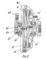
- the invention is applied to a viscous clutch of the general type comprising an internal rotor 10 connected to and driven by a coupling 9 attached to an engine drive shaft (not shown).
- the rotor 10 is positioned within a two part casing 11,12 having a bearing 13 which supports the casing off the coupling or shaft 9 and the rotor has a series of closely spaced annular rings 15 located respectively in annular grooves in the casing end 12 and in an internal partition wall 16.
- This provides a clearance gap on each of the two faces of the rotor of considerably extended area and in operation this clearance gap is filled with a suitable viscous hydraulic fluid to cause torsional drive, or evacuated to allow maximum slip.
- the invention is concerned more particularly with the control of the fluid in this clearance gap so as to vary the drive from the engine shaft to a rotary cooling fan 18 secured to the casing member 12.
- a fluid reservoir 20 is formed between the front wall 11 and an internal partition wall 21 and fluid is continuously pumped from the outer periphery of the clearance space by one or more scoops 22 which convey the oil forwards through an opening 23 into a radial passage 24 leading towards the rotary axis.
- a valve port 25 At the axis there is a valve port 25 through which the fluid flows into the reservoir 20 and returns to the clearance space through a constantly open port 26. This port is not of sufficient size to allow all the oil pumped inwards by the scoop to return to the casing.
- the flow of oil is controlled by a movable valve stem or plunger 30, which is shifted axially into or out of the port 25.
- a movable valve stem or plunger 30 When closing or partly closing the port the flow of fluid inwards from the scoop is restricted, all the fluid drains from the reservoir through the port 26 and the clearance gap in the clutch is fully flooded with the viscous fluid: this provides maximum drive or drag and the fan 18 is driven at close to shaft speed.
- the valve stem 30 is shifted to the left to open the port 25 the scoop delivers fluid at maximum rate inwards along the passage 24 and this being faster than the rate of escape through the port 26 fluid builds up within the reservoir 20 and consequently results in a drainage of oil from the clearance gap.
- the drive through the clutch is therefore reduced, the fan speed 18 falls and the cooling effect on the engine radiator is reduced, as also the power absorbed in the fan drive.
- the valve stem 30 is controlled in this example by a combination of coolant temperature with fan speed or scoop pump pressure.
- the coolant duct is illustrated at 40 which is conveniently the exit from the coolant radiator (not shown).
- a wax capsule 41 is positioned in the coolant passage and its operating stem 42 is positioned in one end of a movable valve stem 43 of a follow-up pressure control valve unit 44.
- the stem 43 moves within an axially floating spool 45 attached to a piston the upper side of which is exposed to atmospheric pressure and to a balancing spring 46.
- the underside of the piston is exposed to pneumatic servo-control pressure at 47, which is communicated via line 48 to the front end of a differential servo unit 50 at the front end of the clutch casing.
- Compressed air to operate the system is admitted to the valve unit 44 at 51, passes through the spool at the port 52 and is controlled by a shoulder 53 on the inner stem.
- This stem also has a tapered end 54 which combines with the spool so that as the coolant temperature rises and the stem lifts the escape of air at the conical end 54 is reduced and flow of pressurised air from the line 51 is increased.
- the spool correspondingly shifts upwards until the follow-up servo effect recreates the balance with increased force in the spring 46 and increased pressure in the working volume below the piston 45.
- the pressure in line 48 always corresponds to the temperature of the coolant.
- the characteristic behaviour of the viscous drive can be varied also by appropriate design of the return flow path from the reservoir 20 to the clearance gap.
- the outermost aperture 26 should be of reduced size.
- the thermal sensing device in each case senses the temperature of an external cooling liquid for the engine or of the cooling air passing over the clutch and through the associated cooling fan. This is by contrast with systems having a thermal control element located inside the viscous fluid clutch sensing the viscous fluid temperature.
- the speed-derived pressure force is opposed directly to the thermal-derived pressure force to control the valve governing return flow of fluid to the clearance gap.
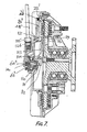
- it is a comparatively simple adjustment to alter the pressure loading of the small spring 140 at the end of the plunger 63 ⁇ .
- it is a comparatively simple adjustment to replace the small spring 140 with a different spring having different pressure loading or other characteristics. This provides a very simple method of altering the balance or relationship between the pump scoop pressure and the thermal sensing pressure.
Landscapes
- Physics & Mathematics (AREA)
- Engineering & Computer Science (AREA)
- Fluid Mechanics (AREA)
- General Physics & Mathematics (AREA)
- Automation & Control Theory (AREA)
- General Engineering & Computer Science (AREA)
- Mechanical Engineering (AREA)
- Hydraulic Clutches, Magnetic Clutches, Fluid Clutches, And Fluid Joints (AREA)
- Frying-Pans Or Fryers (AREA)
- Braking Arrangements (AREA)
- Control Of Fluid Pressure (AREA)
- Cooling, Air Intake And Gas Exhaust, And Fuel Tank Arrangements In Propulsion Units (AREA)
- Mechanical Operated Clutches (AREA)
- Measuring Fluid Pressure (AREA)
- Temperature-Responsive Valves (AREA)
- Valve Device For Special Equipments (AREA)
- Fluid-Driven Valves (AREA)
- Sewing Machines And Sewing (AREA)
Priority Applications (1)
| Application Number | Priority Date | Filing Date | Title |
|---|---|---|---|
| AT88300019T ATE75529T1 (de) | 1987-01-07 | 1988-01-05 | Automatische temperatur- und geschwindigkeitssteuerung fuer fluessigkeitskupplung. |
Applications Claiming Priority (2)
| Application Number | Priority Date | Filing Date | Title |
|---|---|---|---|
| GB878700213A GB8700213D0 (en) | 1987-01-07 | 1987-01-07 | Automatic thermal & speed controls |
| GB8700213 | 1987-03-27 |
Related Child Applications (1)
| Application Number | Title | Priority Date | Filing Date |
|---|---|---|---|
| EP91113232.2 Division-Into | 1988-01-05 |
Publications (3)
| Publication Number | Publication Date |
|---|---|
| EP0274408A2 true EP0274408A2 (fr) | 1988-07-13 |
| EP0274408A3 EP0274408A3 (en) | 1988-10-26 |
| EP0274408B1 EP0274408B1 (fr) | 1992-04-29 |
Family
ID=10610328
Family Applications (2)
| Application Number | Title | Priority Date | Filing Date |
|---|---|---|---|
| EP88300019A Expired - Lifetime EP0274408B1 (fr) | 1987-01-07 | 1988-01-05 | Commande automatique par température et vitesse pour embrayages à fluide visqueux |
| EP19910113232 Withdrawn EP0462628A3 (en) | 1987-01-07 | 1988-01-05 | Pressure modulating valve |
Family Applications After (1)
| Application Number | Title | Priority Date | Filing Date |
|---|---|---|---|
| EP19910113232 Withdrawn EP0462628A3 (en) | 1987-01-07 | 1988-01-05 | Pressure modulating valve |
Country Status (8)
| Country | Link |
|---|---|
| US (1) | US4909367A (fr) |
| EP (2) | EP0274408B1 (fr) |
| AT (1) | ATE75529T1 (fr) |
| BR (1) | BR8800026A (fr) |
| DE (1) | DE3870464D1 (fr) |
| GB (1) | GB8700213D0 (fr) |
| IN (1) | IN169452B (fr) |
| MX (1) | MX161233A (fr) |
Cited By (6)
| Publication number | Priority date | Publication date | Assignee | Title |
|---|---|---|---|---|
| EP0378341A2 (fr) * | 1989-01-13 | 1990-07-18 | Kysor Industrial Corporation | Embrayages à fluide visqueux et soupapes de commande à cet effet |
| US5161659A (en) * | 1989-01-13 | 1992-11-10 | Kysor Industrial Corporation | Viscous fluid shear clutches and control valves therefor |
| US5191915A (en) * | 1989-01-13 | 1993-03-09 | Kysor Industrial Corporation | Viscous fluid shear clutches and control valves therefor |
| US5400823A (en) * | 1989-01-13 | 1995-03-28 | Kysor Industrial Corporation | Viscous fluid shear clutches and control valves therefor |
| DE4413997A1 (de) * | 1994-04-22 | 1995-10-26 | Fichtel & Sachs Ag | Visko-Lüfterkupplung mit Stellantrieb |
| DE19604853A1 (de) * | 1996-02-10 | 1997-08-14 | Behr Gmbh & Co | Elastische Drehmomentstütze |
Families Citing this family (16)
| Publication number | Priority date | Publication date | Assignee | Title |
|---|---|---|---|---|
| US5799765A (en) * | 1990-08-30 | 1998-09-01 | Usui Kokusai Sangyo Kaisha Limited | Fluid clutch |
| JPH0743502U (ja) * | 1993-12-30 | 1995-08-22 | 株式会社ユニシアジェックス | 流体継手 |
| DE4442451A1 (de) * | 1994-11-29 | 1996-05-30 | Behr Gmbh & Co | Flüssigkeitsreibungskupplung |
| US5558192A (en) * | 1995-03-27 | 1996-09-24 | Eaton Corporation | Fluid coupling and external control therefor |
| JP3786374B2 (ja) * | 1995-11-10 | 2006-06-14 | 臼井国際産業株式会社 | 液体クラッチ |
| US6092638A (en) * | 1998-03-05 | 2000-07-25 | Horton, Inc. | Splineless rotational control apparatus |
| DE19837595B4 (de) * | 1998-08-19 | 2004-06-03 | Kuka Roboter Gmbh | Verfahren und Vorrichtung zum Gewichtsausgleich eines Roboterarms |
| JP2000130165A (ja) * | 1998-10-30 | 2000-05-09 | Unisia Jecs Corp | ファンカップリング装置 |
| DE10311347A1 (de) * | 2002-03-29 | 2003-10-09 | Usui Kokusai Sangyo Kk | Temperaturgesteuerte Fluidkupplung |
| US7104382B2 (en) * | 2004-10-21 | 2006-09-12 | Kit Masters Inc. | Clutch system |
| US7438169B2 (en) * | 2004-10-21 | 2008-10-21 | Kit Masters Inc. | Clutch system |
| US8100239B2 (en) * | 2008-01-18 | 2012-01-24 | Kit Masters Inc. | Clutch device and methods |
| US8109375B2 (en) * | 2009-05-07 | 2012-02-07 | Kit Masters Inc. | Clutch systems and methods |
| US9046137B2 (en) | 2010-01-22 | 2015-06-02 | Kit Masters Inc. | Fan clutch apparatus and methods |
| US8360219B2 (en) | 2010-04-26 | 2013-01-29 | Kit Masters, Inc. | Clutch system and methods |
| US20140209180A1 (en) * | 2013-01-27 | 2014-07-31 | Rick L. Boyer | Viscous fan drive systems having fill and scavenge control |
Citations (6)
| Publication number | Priority date | Publication date | Assignee | Title |
|---|---|---|---|---|
| FR2315000A1 (fr) * | 1975-06-20 | 1977-01-14 | Wallace Murray Corp | Groupe d'entrainement de ventilateur a transmission par liquide visqueux pour refroidissement de moteur a combustion interne avec circulation auxiliaire de ce liquide |
| FR2441764A1 (fr) * | 1978-11-16 | 1980-06-13 | Aisin Seiki | Dispositif d'accouplement a fluide visqueux |
| DE3204554A1 (de) * | 1981-02-09 | 1982-08-12 | Aisin Seiki K.K., Kariya, Aichi | Kuehlgeblaeseeinheit fuer eine brennkraftmaschine |
| DE3242381A1 (de) * | 1981-11-30 | 1983-06-09 | Aisin Seiki K.K., Kariya, Aichi | Fluessigkeitskupplung |
| EP0105647A1 (fr) * | 1982-09-30 | 1984-04-18 | Household Manufacturing, Inc. | Dispositif d'accouplement à fluide visqueux |
| EP0130724A1 (fr) * | 1983-06-29 | 1985-01-09 | Eaton Corporation | Dispositif d'accouplement à fluide et mécanisme de soupape utilisable là-dedans |
Family Cites Families (20)
| Publication number | Priority date | Publication date | Assignee | Title |
|---|---|---|---|---|
| FR1212283A (fr) * | 1958-10-01 | 1960-03-23 | Perfectionnements aux valves de décharge | |
| US3159254A (en) * | 1962-01-11 | 1964-12-01 | Schwitzer Corp | Speed responsive coupling device |
| US3144922A (en) * | 1962-04-05 | 1964-08-18 | Schwitzer Corp | Temperature and speed responsive fluid coupling |
| US3363734A (en) * | 1962-09-17 | 1968-01-16 | Eaton Yale & Towne | Temperature responsive fluid clutch |
| US3217849A (en) * | 1962-10-02 | 1965-11-16 | Schwitzer Corp | Speed and temperature controlled coupling device |
| US3191733A (en) * | 1963-01-07 | 1965-06-29 | Schwitzer Corp | Torque transmitting fluid coupling |
| US3194372A (en) * | 1963-03-06 | 1965-07-13 | Schwitzer Corp | Variable volume coupling mechanism |
| US3444748A (en) * | 1967-02-01 | 1969-05-20 | Eaton Yale & Towne | Drive mechanism |
| GB1377476A (en) * | 1970-11-21 | 1974-12-18 | Dynair Ltd | Fan drives |
| GB1395690A (en) * | 1973-12-18 | 1975-05-29 | Dynair Ltd | Thermally actuated control valves |
| US3961606A (en) * | 1975-01-02 | 1976-06-08 | Standard-Thomson Corporation | Thermally responsive fluid control valve |
| US4116318A (en) * | 1977-04-05 | 1978-09-26 | Eaton Corporation | Fluid flow restriction path in viscous fluid clutch |
| US4176630A (en) * | 1977-06-01 | 1979-12-04 | Dynair Limited | Automatic control valves |
| US4285467A (en) * | 1977-10-12 | 1981-08-25 | Eaton Corporation | Three-port thermally responsive valve |
| US4189095A (en) * | 1978-11-02 | 1980-02-19 | Kysor Industrial Corporation | Combination valve |
| US4351426A (en) * | 1980-12-29 | 1982-09-28 | Eaton Corporation | Single stage control for viscous fluid coupling |
| US4437554A (en) * | 1981-06-19 | 1984-03-20 | Household Manufacturing Inc. | Fluid shear coupling apparatus |
| DE3211337C2 (de) * | 1982-03-27 | 1984-08-09 | J.M. Voith Gmbh, 7920 Heidenheim | Hydrodynamische Regelkupplung |
| DE3333268A1 (de) * | 1983-09-15 | 1985-04-18 | Süddeutsche Kühlerfabrik Julius Fr. Behr GmbH & Co KG, 7000 Stuttgart | Verfahren zur steuerung der abtriebsdrehzahl einer fluessigkeitsreibungskupplung und vorrichtung zur durchfuehrung des verfahrens |
| US4653624A (en) * | 1986-05-27 | 1987-03-31 | Household Manufacturing, Inc. | Fluid shear coupling apparatus having fluid modulating valve |
-
1987
- 1987-01-07 GB GB878700213A patent/GB8700213D0/en active Pending
-
1988
- 1988-01-05 EP EP88300019A patent/EP0274408B1/fr not_active Expired - Lifetime
- 1988-01-05 DE DE8888300019T patent/DE3870464D1/de not_active Expired - Lifetime
- 1988-01-05 AT AT88300019T patent/ATE75529T1/de not_active IP Right Cessation
- 1988-01-05 US US07/140,990 patent/US4909367A/en not_active Expired - Fee Related
- 1988-01-05 EP EP19910113232 patent/EP0462628A3/en not_active Withdrawn
- 1988-01-06 BR BR8800026A patent/BR8800026A/pt unknown
- 1988-01-06 IN IN13/CAL/88A patent/IN169452B/en unknown
- 1988-01-07 MX MX10016A patent/MX161233A/es unknown
Patent Citations (6)
| Publication number | Priority date | Publication date | Assignee | Title |
|---|---|---|---|---|
| FR2315000A1 (fr) * | 1975-06-20 | 1977-01-14 | Wallace Murray Corp | Groupe d'entrainement de ventilateur a transmission par liquide visqueux pour refroidissement de moteur a combustion interne avec circulation auxiliaire de ce liquide |
| FR2441764A1 (fr) * | 1978-11-16 | 1980-06-13 | Aisin Seiki | Dispositif d'accouplement a fluide visqueux |
| DE3204554A1 (de) * | 1981-02-09 | 1982-08-12 | Aisin Seiki K.K., Kariya, Aichi | Kuehlgeblaeseeinheit fuer eine brennkraftmaschine |
| DE3242381A1 (de) * | 1981-11-30 | 1983-06-09 | Aisin Seiki K.K., Kariya, Aichi | Fluessigkeitskupplung |
| EP0105647A1 (fr) * | 1982-09-30 | 1984-04-18 | Household Manufacturing, Inc. | Dispositif d'accouplement à fluide visqueux |
| EP0130724A1 (fr) * | 1983-06-29 | 1985-01-09 | Eaton Corporation | Dispositif d'accouplement à fluide et mécanisme de soupape utilisable là-dedans |
Cited By (10)
| Publication number | Priority date | Publication date | Assignee | Title |
|---|---|---|---|---|
| EP0378341A2 (fr) * | 1989-01-13 | 1990-07-18 | Kysor Industrial Corporation | Embrayages à fluide visqueux et soupapes de commande à cet effet |
| EP0378341A3 (fr) * | 1989-01-13 | 1990-09-26 | Kysor Industrial Corporation | Embrayages à fluide visqueux et soupapes de commande à cet effet |
| US5042629A (en) * | 1989-01-13 | 1991-08-27 | Kysor Industrial Corporation | Viscous fluid shear clutches and control valves therefor |
| US5161659A (en) * | 1989-01-13 | 1992-11-10 | Kysor Industrial Corporation | Viscous fluid shear clutches and control valves therefor |
| US5191915A (en) * | 1989-01-13 | 1993-03-09 | Kysor Industrial Corporation | Viscous fluid shear clutches and control valves therefor |
| US5400823A (en) * | 1989-01-13 | 1995-03-28 | Kysor Industrial Corporation | Viscous fluid shear clutches and control valves therefor |
| DE4413997A1 (de) * | 1994-04-22 | 1995-10-26 | Fichtel & Sachs Ag | Visko-Lüfterkupplung mit Stellantrieb |
| DE4413997C2 (de) * | 1994-04-22 | 1999-01-21 | Mannesmann Sachs Ag | Visko-Lüfterkupplung mit Stellantrieb |
| DE19604853A1 (de) * | 1996-02-10 | 1997-08-14 | Behr Gmbh & Co | Elastische Drehmomentstütze |
| DE19604853B4 (de) * | 1996-02-10 | 2006-01-12 | Behr Gmbh & Co. Kg | Elastische Drehmomentstütze |
Also Published As
| Publication number | Publication date |
|---|---|
| EP0274408B1 (fr) | 1992-04-29 |
| EP0274408A3 (en) | 1988-10-26 |
| EP0462628A2 (fr) | 1991-12-27 |
| US4909367A (en) | 1990-03-20 |
| DE3870464D1 (de) | 1992-06-04 |
| IN169452B (fr) | 1991-10-19 |
| MX161233A (es) | 1990-08-24 |
| GB8700213D0 (en) | 1987-02-11 |
| EP0462628A3 (en) | 1992-02-26 |
| ATE75529T1 (de) | 1992-05-15 |
| BR8800026A (pt) | 1988-08-02 |
Similar Documents
| Publication | Publication Date | Title |
|---|---|---|
| US4909367A (en) | Automatic thermal and speed controls for viscous fluid clutches | |
| US4680928A (en) | Warm-up promotion device for automatic transmission | |
| CA1116419A (fr) | Circuit de commande pour soupape de purge | |
| KR920008643B1 (ko) | 온도감응식 팬 유체 커플링 | |
| US4597481A (en) | Hydrodynamic control coupling | |
| US4201050A (en) | Fluid coupling | |
| US4203712A (en) | Single or plural variable displacement pump control with an improved flow metering valve | |
| CA1048895A (fr) | Soupapes d'accouplement fluide | |
| US3339689A (en) | Temperature responsive fluid coupling device | |
| US4134484A (en) | Fluid coupling | |
| US4420114A (en) | Liquid heating system | |
| US4200146A (en) | Method and apparatus for hydraulically driving and controlling a cooling fan | |
| US4591317A (en) | Dual pump controls | |
| US2530241A (en) | Power transmission for refrigerated motor vehicles | |
| US4662495A (en) | Fluid-friction coupling for a cooling fan of an internal combustion engine | |
| US6494797B1 (en) | Automatic transmission assembly and method of operating the same | |
| US4072443A (en) | Control valve arrangements for variable stroke pumps | |
| JPH0355698B2 (fr) | ||
| US5042629A (en) | Viscous fluid shear clutches and control valves therefor | |
| US4377989A (en) | Air-cooled internal combustion engine having a cooling air blower driven by a hydraulic coupling | |
| US3483852A (en) | Fluid coupling fan drive | |
| EP0157794A1 (fr) | Systeme generateur d'energie hydraulique a turbine a air sous pression dynamique | |
| JPH05263766A (ja) | 水力学的機器用の水力学的装置 | |
| US4924986A (en) | Viscous fluid clutches | |
| US4426196A (en) | Oil supply system |
Legal Events
| Date | Code | Title | Description |
|---|---|---|---|
| PUAI | Public reference made under article 153(3) epc to a published international application that has entered the european phase |
Free format text: ORIGINAL CODE: 0009012 |
|
| AK | Designated contracting states |
Kind code of ref document: A2 Designated state(s): AT BE CH DE ES FR GB IT LI LU NL SE |
|
| PUAL | Search report despatched |
Free format text: ORIGINAL CODE: 0009013 |
|
| AK | Designated contracting states |
Kind code of ref document: A3 Designated state(s): AT BE CH DE ES FR GB IT LI LU NL SE |
|
| 17P | Request for examination filed |
Effective date: 19890410 |
|
| 17Q | First examination report despatched |
Effective date: 19900220 |
|
| RAP1 | Party data changed (applicant data changed or rights of an application transferred) |
Owner name: KYSOR INDUSTRIAL CORPORATION |
|
| GRAA | (expected) grant |
Free format text: ORIGINAL CODE: 0009210 |
|
| AK | Designated contracting states |
Kind code of ref document: B1 Designated state(s): AT BE CH DE ES FR GB IT LI LU NL SE |
|
| PG25 | Lapsed in a contracting state [announced via postgrant information from national office to epo] |
Ref country code: IT Free format text: LAPSE BECAUSE OF FAILURE TO SUBMIT A TRANSLATION OF THE DESCRIPTION OR TO PAY THE FEE WITHIN THE PRE;WARNING: LAPSES OF ITALIAN PATENTS WITH EFFECTIVE DATE BEFORE 2007 MAY HAVE OCCURRED AT ANY TIME BEFORE 2007. THE CORRECT EFFECTIVE DATE MAY BE DIFFERENT FROM THE ONE RECORDED.SCRIBED TIME-LIMIT Effective date: 19920429 Ref country code: CH Effective date: 19920429 Ref country code: LI Effective date: 19920429 Ref country code: NL Effective date: 19920429 Ref country code: SE Effective date: 19920429 Ref country code: AT Effective date: 19920429 Ref country code: BE Effective date: 19920429 Ref country code: ES Free format text: THE PATENT HAS BEEN ANNULLED BY A DECISION OF A NATIONAL AUTHORITY Effective date: 19920429 |
|
| REF | Corresponds to: |
Ref document number: 75529 Country of ref document: AT Date of ref document: 19920515 Kind code of ref document: T |
|
| REF | Corresponds to: |
Ref document number: 3870464 Country of ref document: DE Date of ref document: 19920604 |
|
| ET | Fr: translation filed | ||
| REG | Reference to a national code |
Ref country code: CH Ref legal event code: PL |
|
| NLV1 | Nl: lapsed or annulled due to failure to fulfill the requirements of art. 29p and 29m of the patents act | ||
| PG25 | Lapsed in a contracting state [announced via postgrant information from national office to epo] |
Ref country code: GB Effective date: 19930105 |
|
| PG25 | Lapsed in a contracting state [announced via postgrant information from national office to epo] |
Ref country code: LU Free format text: LAPSE BECAUSE OF NON-PAYMENT OF DUE FEES Effective date: 19930131 |
|
| PLBE | No opposition filed within time limit |
Free format text: ORIGINAL CODE: 0009261 |
|
| STAA | Information on the status of an ep patent application or granted ep patent |
Free format text: STATUS: NO OPPOSITION FILED WITHIN TIME LIMIT |
|
| 26N | No opposition filed | ||
| GBPC | Gb: european patent ceased through non-payment of renewal fee |
Effective date: 19930105 |
|
| PG25 | Lapsed in a contracting state [announced via postgrant information from national office to epo] |
Ref country code: FR Effective date: 19930930 |
|
| PG25 | Lapsed in a contracting state [announced via postgrant information from national office to epo] |
Ref country code: DE Effective date: 19931001 |
|
| REG | Reference to a national code |
Ref country code: FR Ref legal event code: ST |