EP0273701A2 - Hydraulikkolben und- zylindereinheiten - Google Patents
Hydraulikkolben und- zylindereinheiten Download PDFInfo
- Publication number
- EP0273701A2 EP0273701A2 EP87311349A EP87311349A EP0273701A2 EP 0273701 A2 EP0273701 A2 EP 0273701A2 EP 87311349 A EP87311349 A EP 87311349A EP 87311349 A EP87311349 A EP 87311349A EP 0273701 A2 EP0273701 A2 EP 0273701A2
- Authority
- EP
- European Patent Office
- Prior art keywords
- piston
- bore
- insert
- cylinder assembly
- assembly
- Prior art date
- Legal status (The legal status is an assumption and is not a legal conclusion. Google has not performed a legal analysis and makes no representation as to the accuracy of the status listed.)
- Withdrawn
Links
Images
Classifications
-
- F—MECHANICAL ENGINEERING; LIGHTING; HEATING; WEAPONS; BLASTING
- F16—ENGINEERING ELEMENTS AND UNITS; GENERAL MEASURES FOR PRODUCING AND MAINTAINING EFFECTIVE FUNCTIONING OF MACHINES OR INSTALLATIONS; THERMAL INSULATION IN GENERAL
- F16D—COUPLINGS FOR TRANSMITTING ROTATION; CLUTCHES; BRAKES
- F16D65/00—Parts or details
- F16D65/14—Actuating mechanisms for brakes; Means for initiating operation at a predetermined position
- F16D65/16—Actuating mechanisms for brakes; Means for initiating operation at a predetermined position arranged in or on the brake
- F16D65/22—Actuating mechanisms for brakes; Means for initiating operation at a predetermined position arranged in or on the brake adapted for pressing members apart, e.g. for drum brakes
-
- F—MECHANICAL ENGINEERING; LIGHTING; HEATING; WEAPONS; BLASTING
- F16—ENGINEERING ELEMENTS AND UNITS; GENERAL MEASURES FOR PRODUCING AND MAINTAINING EFFECTIVE FUNCTIONING OF MACHINES OR INSTALLATIONS; THERMAL INSULATION IN GENERAL
- F16D—COUPLINGS FOR TRANSMITTING ROTATION; CLUTCHES; BRAKES
- F16D65/00—Parts or details
- F16D65/14—Actuating mechanisms for brakes; Means for initiating operation at a predetermined position
-
- F—MECHANICAL ENGINEERING; LIGHTING; HEATING; WEAPONS; BLASTING
- F16—ENGINEERING ELEMENTS AND UNITS; GENERAL MEASURES FOR PRODUCING AND MAINTAINING EFFECTIVE FUNCTIONING OF MACHINES OR INSTALLATIONS; THERMAL INSULATION IN GENERAL
- F16D—COUPLINGS FOR TRANSMITTING ROTATION; CLUTCHES; BRAKES
- F16D2127/00—Auxiliary mechanisms
- F16D2127/08—Self-amplifying or de-amplifying mechanisms
Definitions
- This invention relates to piston and cylinder assemblies for vehicle hydraulic systems.
- U.S. No. 4 454 632 shows a disposable shipping and installation strap which performs this function.
- the strap has a retaining member, fitted over the end of the output member (on which the piston acts), with two or more strips integrally formed with the retaining member, and attached at their free ends to the exterior of the cylinder housing.
- Each strip has a reduced strength portion which breaks on first hydraulic operation of the actuator to free the output member.
- a piston and cylinder assembly for a vehicle hydraulic system comprises a cylinder body having a bore and piston means working in the bore, and retaining means to hold the piston means in its retracted position, whereby to maintain the effective length of the assembly at a predetermined value for installation, until the assembly is operated hydraulically, and the retaining means comprises an insert acting between the piston means and the bore, the insert having a releasable frictional engagement in the bore, and acting as an abutment to hold the piston means in its retracted position.
- the insert provides a simple way of maintaining the effective length of the assembly during installation without complicating the assembly. It is released when the assembly is first operated hydraulically, being urged out of engagement with the bore by movement of the piston means.
- the insert When the insert is released from the bore it does not re-enter the bore. Preferably, it is held captive on the piston means, so there are no loose parts to fall off.
- the insert When the insert is in position in the assembly, low pressure bleeding of the assembly can be performed without releasing the piston means. This minimises the volume to be bled.
- the insert also acts as a dirt shield for the assembly, and as a visual indicator of whether or not the assembly has been actuated hydraulically.
- the insert comprises a resilient clip, having an abutment plate with a central opening to receive a reduced diameter portion of the piston means, and a flange extending axially from the outer peripheral edge of the plate for frictional engagement in the bore.
- the insert may comprise a light metal pressing or a one-piece moulding of plastics material.
- the piston and cylinder assembly is an actuator for a self-energising disc brake, it comprises a cylinder body having a longitudinal through-bore in which works a pair of opposed brake actuating pistons, and an insert acts between each piston and portions of the bore at opposite ends of the cylinder body.
- the assembly is a slave cylinder for a vehicle clutch system it comprises a cylinder body with a bore in which works a slave piston operating an output rod for connection to the clutch operating mechanism, and an insert acts between the piston and a portion of the bore.
- the central opening in the insert receives the output rod, which holds the insert when it is released from the bore.
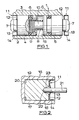
- the piston and cylinder assembly 1 of Figure 1 is adapted for incorporation in a disc brake of the self-energising kind.
- a brake (not shown) comprises a pair of rotatable friction discs provided on opposite sides with linings of friction material which are adapted to be brought into engagement with spaced opposed radial surfaces in a housing by pressure plates located between the discs and centred by three angularly spaced stationary pilots and urged towards each other by tension return springs coupled to the plates at opposite ends.
- Balls or rollers are located in co-operating oppositely inclined recesses in the opposite faces of the pressure plates which are adjacent in the brake.
- the application of the brake is initiated by moving the pressure plates angularly in opposite directions which causes the pressure plates to move axially relatively away from each other due to the tendency for the balls or rollers to ride up ramps defined by the end faces of the recesses. This urges the friction discs into engagement with the faces in the housing.
- the pressure plates are then carried round with the discs until one is arrested by the engagement of a lug on a respective plate with a drag-taking abutment, whereafter continued angular movement of the other plate provides a servo action.
- the brake is applied mechanically for parking or in an emergency by a pull-rod (not shown) which extends through a radial opening in the housing and is coupled to the outer ends of a pair of toggle links of which the inner ends are pivotally connected to respective pressure plates.
- a pull-rod (not shown) which extends through a radial opening in the housing and is coupled to the outer ends of a pair of toggle links of which the inner ends are pivotally connected to respective pressure plates.
- the brake is applied hydraulically by the hydraulic actuator 1 which acts between lugs on the respective pressure plates.
- the lugs are displaced angularly from the toggle links.
- the hydraulic actuator 1 comprises a cylinder 2 which is carried from the housing of the brake and has a longitudinally extending open-ended bore 3 in which work a pair of opposed pistons 4, 5 each provided with a seal 6 adjacent to its inner end. Each piston has at its outer end a projection 7 of reduced diameter.
- a compression spring 8 received at one end in a recess 9 in the inner end of the piston 4 and in abutment with the inner end of the piston 5, acts to urge the pistons 4, 5 relatively away from each other.
- the spring 8 is located by means of a projection 10 on the piston 5, and the projection 10 is telescopically received within the recess 9.
- the spring 8 enables the pistons 4, 5 to follow up relative displacements of the pressure plates caused by adjustment for wear of the friction linings, as well as overcoming seal friction and eliminating the effect of a vibrational piston "knock-back".
- the spring is chosen so that it is easily overpowered by the return springs, but has enough force to respond quickly to a sudden reduction in its working length.
- Piston retaining means in the form of inserts 11 are incorporated in the actuator 1 for each piston.
- each insert 11 comprises a clip suitably in the form of a light metal pressing.
- Each pressing comprises a circular abutment plate 12 against which the outer end of the respective piston abuts, and the plate has a central aperture 13 through which the projection 7 on the respective piston extends, and an annular flange 14 which extends axially from the peripheral edge of the plate 12 in a direction away from the respective piston.
- the flanges 14 engage frictionally, suitably with interference, with the portions of the bore 3 at the outer ends of the cylinder 2 to hold the pistons 4, 5 in retracted positions in the bore 3 in which the spring 8 is compressed and the projection 10 is received in the recess 9.
- the inserts 11 act as dirt shields to prevent the ingress of dirt into the ends of the cylinder bore 7.
- the system can be bled at low pressure without release of the pistons. This therefore minimises the volume to be bled.
- both pistons 4 and 5 move relatively away from each other and the two inserts 11 are urged out of the bore 3, as shown at the right hand end of the drawing.
- the two inserts 11 are then held in loose captivity on the extensions 7 and they will not re-enter the bore 3 once they have been released from it.
- the piston and cylinder assembly 16 of Figure 2 is a slave cylinder for a vehicle clutch system.
- the slave cylinder comprises a cylinder body 17, with a single-ended bore 18 in which works the slave piston 19.
- the piston 19 is actuated by pressurisation of a pressure space 20 in response to operation of a clutch master cylinder (not shown) by a pedal.
- the piston 19 operates an output rod 21, having a hemispherical end 22 received in a recess 23 in the forward end of the piston 19.
- the other end of the rod 21 is adapted to operate a clutch release mechanism (not shown).
- the assembly 16 incorporates piston retaining means in the form of an insert 11 similar to that shown in Figure 1. It will be noted that the rod 21, rather than a projection on the piston, extends through the central aperture 13 of the insert 11.
- the flange 14 engages frictionally with the bore 18 to hold the piston 19 and the rod 21 in their retracted positions.
- the master cylinder can then be connected to the slave cylinder, filled with hydraulic fluid and bled at low pressure to form a sub-assembly which can be transported and installed in a vehicle, all without releasing the piston 19.
- the insert 11 could be used in other piston and cylinder assemblies as required.
- the insert 11 may comprise a one-piece plastics moulding.
Landscapes
- Engineering & Computer Science (AREA)
- General Engineering & Computer Science (AREA)
- Mechanical Engineering (AREA)
- Braking Arrangements (AREA)
- Hydraulic Clutches, Magnetic Clutches, Fluid Clutches, And Fluid Joints (AREA)
Applications Claiming Priority (4)
| Application Number | Priority Date | Filing Date | Title |
|---|---|---|---|
| GB8700040 | 1987-01-03 | ||
| GB878700040A GB8700040D0 (en) | 1987-01-03 | 1987-01-03 | Self-energising disc brakes |
| GB8719111 | 1987-08-12 | ||
| GB878719111A GB8719111D0 (en) | 1987-01-03 | 1987-08-12 | Hydraulic piston & cylinder assemblies |
Publications (2)
| Publication Number | Publication Date |
|---|---|
| EP0273701A2 true EP0273701A2 (de) | 1988-07-06 |
| EP0273701A3 EP0273701A3 (de) | 1989-12-27 |
Family
ID=26291756
Family Applications (1)
| Application Number | Title | Priority Date | Filing Date |
|---|---|---|---|
| EP87311349A Withdrawn EP0273701A3 (de) | 1987-01-03 | 1987-12-23 | Hydraulikkolben und- zylindereinheiten |
Country Status (2)
| Country | Link |
|---|---|
| US (1) | US4809588A (de) |
| EP (1) | EP0273701A3 (de) |
Cited By (1)
| Publication number | Priority date | Publication date | Assignee | Title |
|---|---|---|---|---|
| WO2007024137A1 (en) * | 2005-08-24 | 2007-03-01 | Kongsberg Automotive As | Pneumatic installation of cylinder (pic) |
Families Citing this family (1)
| Publication number | Priority date | Publication date | Assignee | Title |
|---|---|---|---|---|
| ATE504754T1 (de) * | 2005-01-14 | 2011-04-15 | Volvo Lastvagnar Ab | Stellglied für eine fahrzeugkupplung |
Family Cites Families (39)
| Publication number | Priority date | Publication date | Assignee | Title |
|---|---|---|---|---|
| DE657010C (de) * | 1934-06-23 | 1938-02-22 | Kerb Konus G M B H | Stopfensicherung, insbesondere fuer Kolbenbolzen von Brennkraftmaschinen |
| US2685275A (en) * | 1949-07-14 | 1954-08-03 | Electro Hydraulics Ltd | Pressure fluid servomotor |
| US2708994A (en) * | 1951-03-23 | 1955-05-24 | Gen Tire & Rubber Co | Expanded clutch |
| US2766473A (en) * | 1952-08-22 | 1956-10-16 | Rubberset Company | Rotary paint applicator |
| DE941448C (de) * | 1952-12-16 | 1956-04-12 | Kurt Weber | Schalungslos herzustellende Stahlbetonrippendecke aus vorgefertigten -foermigen Deckenbalken, Deckenplatten und zwischen den Decken-platten liegenden Ortbetonrippen |
| US2790597A (en) * | 1954-06-14 | 1957-04-30 | Hauck Mfg Co | Pump |
| US2851995A (en) * | 1955-07-20 | 1958-09-16 | Cleveland Pneumatic Ind Inc | Lock mechanism |
| US2904825A (en) * | 1957-11-01 | 1959-09-22 | Bommer Spring Hinge Co Inc | Mechanical connections |
| US2880641A (en) * | 1958-08-01 | 1959-04-07 | Palnut Company | Push-on fastener with torsion spring teeth |
| US3138929A (en) * | 1961-02-16 | 1964-06-30 | Thompson Ramo Wooldridge Inc | Multiple stage expulsion piston |
| US3429410A (en) * | 1967-10-31 | 1969-02-25 | Quinten A Hansen | Clutch with non-rotatable fluid motor |
| GB1164959A (en) * | 1968-08-05 | 1969-09-24 | Renak Werke Veb | Improvements in or relating to Hydraulic Internal Shoe-Drum Brakes. |
| GB1345158A (en) * | 1970-06-24 | 1974-01-30 | Girling Ltd | Vehicle wheel brakes |
| SE380588B (sv) * | 1973-12-21 | 1975-11-10 | Foerenade Fabriksverken | Arbetscylinder med i valfritt lege lasbar kolv |
| US3983969A (en) * | 1974-12-16 | 1976-10-05 | The Bendix Corporation | Disc brake caliper and friction pad mounting |
| US4391544A (en) * | 1974-12-16 | 1983-07-05 | Sps Technologies, Inc. | Self-retained fastener |
| US4077550A (en) * | 1976-06-21 | 1978-03-07 | Voplex Corporation | Interlock with inside of cylinder |
| US4086996A (en) * | 1976-12-28 | 1978-05-02 | Borg-Warner Corporation | Self-adjusting clutch release bearing carrier assembly |
| CA1109366A (en) * | 1977-10-21 | 1981-09-22 | Andrew Stratienko | Locking device for hydraulic actuator |
| FR2427506A1 (fr) * | 1978-06-02 | 1979-12-28 | Citroen Sa | Jonc elastique d'immobilisation de pieces cannelees ou dentelees |
| US4263840A (en) * | 1979-10-29 | 1981-04-28 | Stratobrake Corporation | Safety brake mechanism |
| US4509764A (en) * | 1981-11-12 | 1985-04-09 | Skf Kugellagerfabriken Gmbh | Sealing arrangement |
| US4454632A (en) * | 1982-02-01 | 1984-06-19 | Automotive Products Plc | Shipping and installation strap for linear actuator |
| US4557361A (en) * | 1982-02-01 | 1985-12-10 | Automotive Products Plc | Shipping and installation strap for linear actuator |
| US4551976A (en) * | 1982-02-01 | 1985-11-12 | Automotive Products Plc | Shipping and installation strap for linear actuator |
| SU1052744A1 (ru) * | 1982-02-09 | 1983-11-07 | Eltsin Viktor | Силовой цилиндр |
| GB2121504B (en) * | 1982-05-28 | 1985-09-18 | Automotive Products Plc | Hydraulic slave cylinder for clutch release |
| FR2528526A1 (fr) * | 1982-06-09 | 1983-12-16 | Sfr Sa Robinetterie | Butee se fixant dans un alesage d'un dispositif |
| US4480530A (en) * | 1982-06-28 | 1984-11-06 | Aeroquip Corporation | Braking actuator |
| DE3246349A1 (de) * | 1982-12-15 | 1984-06-20 | FAG Kugelfischer Georg Schäfer KGaA, 8720 Schweinfurt | Geberzylinder |
| US4585109A (en) * | 1983-03-21 | 1986-04-29 | Automotive Products Plc | Motor vehicle clutch control mechanism |
| GB2138536B (en) * | 1983-04-15 | 1986-07-02 | Wool Dev Int | Applicator piston |
| US4480368A (en) * | 1983-05-02 | 1984-11-06 | Caterpillar Tractor Co. | Unitary installation of engine cylinder liner, piston and rod |
| US4581979A (en) * | 1983-07-01 | 1986-04-15 | Automotive Products Plc | Shipping and installation restraining clip for master cylinder input member |
| JPS6016029U (ja) * | 1983-07-14 | 1985-02-02 | 株式会社 ニフコ | ピストンシリンダ型ダンパ− |
| US4756159A (en) * | 1983-11-28 | 1988-07-12 | Automotive Products Plc | Prefilling apparatus for modular prefilled hydraulic control apparatus |
| US4607670A (en) * | 1983-11-28 | 1986-08-26 | Automotive Products Plc | Modular prefilled hydraulic control apparatus |
| US4665802A (en) * | 1985-03-07 | 1987-05-19 | Automotive Products Plc | Shipping and installation restraining strap for slave cylinder |
| EP0203729A1 (de) * | 1985-05-01 | 1986-12-03 | LUCAS INDUSTRIES public limited company | Scheibenbremsen mit Selbstverstärkung |
-
1987
- 1987-12-23 EP EP87311349A patent/EP0273701A3/de not_active Withdrawn
- 1987-12-29 US US07/138,929 patent/US4809588A/en not_active Expired - Fee Related
Cited By (2)
| Publication number | Priority date | Publication date | Assignee | Title |
|---|---|---|---|---|
| WO2007024137A1 (en) * | 2005-08-24 | 2007-03-01 | Kongsberg Automotive As | Pneumatic installation of cylinder (pic) |
| CN101287914B (zh) * | 2005-08-24 | 2011-07-06 | 孔斯贝格汽车公司 | 缸体气动设备 |
Also Published As
| Publication number | Publication date |
|---|---|
| US4809588A (en) | 1989-03-07 |
| EP0273701A3 (de) | 1989-12-27 |
Similar Documents
| Publication | Publication Date | Title |
|---|---|---|
| US4576255A (en) | Multi-disc brakes | |
| US4494630A (en) | Floating-caliper spot-type disc brake | |
| US3633715A (en) | Disc brake with spring brake and pressure-compensating self-adjuster | |
| CA2140342A1 (en) | Elevator Brake with Shoes Actuated by Springs | |
| CA2048021A1 (en) | Spring-applied, hydraulically released brake actuator having positive clearance slack adjuster mechanism | |
| US3966028A (en) | Automatic brake adjusting mechanism | |
| US3805924A (en) | Rear disc brake with integral ball ramp parking | |
| US4611691A (en) | Hydraulic actuator assemblies for vehicle brakes | |
| US4550810A (en) | Disc brakes for vehicles | |
| US3842949A (en) | Disc brakes | |
| US3365029A (en) | Adjusting means for disk brakes | |
| US3651896A (en) | Hydraulic disk brake with mechanical actuator | |
| CA1203757A (en) | Wedge actuated drum brake assembly | |
| EP0676557B1 (de) | Bremsbetätiger mit hülsenartigem Spielnachsteller | |
| US4809588A (en) | Hydraulic piston and cylinder assemblies | |
| GB2097876A (en) | A disc brake with caliper retract mechanism | |
| US3860095A (en) | Vehicle brakes | |
| EP0260100A1 (de) | Scheibenbremsen mit Selbstverstärkung | |
| US4269290A (en) | Guiding device for brake pad supports of a spot-type disc brake | |
| US3486593A (en) | Hydraulic disk brake with anti-knock back feature | |
| US4549636A (en) | Disc brakes for vehicles | |
| US4276963A (en) | Spreading disc brakes for vehicles | |
| EP0203729A1 (de) | Scheibenbremsen mit Selbstverstärkung | |
| US4343381A (en) | Disc brake friction pad retaining means and guide seal | |
| US3489253A (en) | Disk brake including automatic adjusting mechanism |
Legal Events
| Date | Code | Title | Description |
|---|---|---|---|
| PUAI | Public reference made under article 153(3) epc to a published international application that has entered the european phase |
Free format text: ORIGINAL CODE: 0009012 |
|
| AK | Designated contracting states |
Kind code of ref document: A2 Designated state(s): DE FR GB IT |
|
| PUAL | Search report despatched |
Free format text: ORIGINAL CODE: 0009013 |
|
| AK | Designated contracting states |
Kind code of ref document: A3 Designated state(s): DE FR GB IT |
|
| 17P | Request for examination filed |
Effective date: 19900531 |
|
| 17Q | First examination report despatched |
Effective date: 19910708 |
|
| STAA | Information on the status of an ep patent application or granted ep patent |
Free format text: STATUS: THE APPLICATION HAS BEEN WITHDRAWN |
|
| 18W | Application withdrawn |
Withdrawal date: 19911121 |
|
| R18W | Application withdrawn (corrected) |
Effective date: 19911121 |