EP0273254B1 - Method and device for pouring bulk material, especially coffee - Google Patents
Method and device for pouring bulk material, especially coffee Download PDFInfo
- Publication number
- EP0273254B1 EP0273254B1 EP87118218A EP87118218A EP0273254B1 EP 0273254 B1 EP0273254 B1 EP 0273254B1 EP 87118218 A EP87118218 A EP 87118218A EP 87118218 A EP87118218 A EP 87118218A EP 0273254 B1 EP0273254 B1 EP 0273254B1
- Authority
- EP
- European Patent Office
- Prior art keywords
- bags
- tare
- weight
- value
- balance
- Prior art date
- Legal status (The legal status is an assumption and is not a legal conclusion. Google has not performed a legal analysis and makes no representation as to the accuracy of the status listed.)
- Expired - Lifetime
Links
Images


Classifications
-
- G—PHYSICS
- G01—MEASURING; TESTING
- G01G—WEIGHING
- G01G15/00—Arrangements for check-weighing of materials dispensed into removable containers
- G01G15/02—Arrangements for check-weighing of materials dispensed into removable containers with provision for adding or removing a make-up quantity of material to obtain the desired net weight
-
- B—PERFORMING OPERATIONS; TRANSPORTING
- B65—CONVEYING; PACKING; STORING; HANDLING THIN OR FILAMENTARY MATERIAL
- B65B—MACHINES, APPARATUS OR DEVICES FOR, OR METHODS OF, PACKAGING ARTICLES OR MATERIALS; UNPACKING
- B65B1/00—Packaging fluent solid material, e.g. powders, granular or loose fibrous material, loose masses of small articles, in individual containers or receptacles, e.g. bags, sacks, boxes, cartons, cans, or jars
- B65B1/30—Devices or methods for controlling or determining the quantity or quality or the material fed or filled
- B65B1/32—Devices or methods for controlling or determining the quantity or quality or the material fed or filled by weighing
-
- G—PHYSICS
- G01—MEASURING; TESTING
- G01G—WEIGHING
- G01G23/00—Auxiliary devices for weighing apparatus
- G01G23/14—Devices for determining tare weight or for cancelling out the tare by zeroising, e.g. mechanically operated
- G01G23/16—Devices for determining tare weight or for cancelling out the tare by zeroising, e.g. mechanically operated electrically or magnetically operated
- G01G23/166—Devices for determining tare weight or for cancelling out the tare by zeroising, e.g. mechanically operated electrically or magnetically operated involving comparison with a reference value
Definitions
- the invention relates to a method for filling bulk goods, in particular coffee, and a device for carrying out the method according to the preamble of patent claims 1 and 11 respectively.
- the tare weight i.e. the weight of the bags to be filled
- certain fluctuations cannot be avoided either, since the thickness of the films from which the bags are made is only constant within certain limits due to the (known) manufacturing processes (bubbles). Since the cuts are the same for each bag, there are fluctuations in the tare weight, which are currently around 8%.
- the present invention is based on the object of developing methods and apparatus of the type mentioned at the outset in such a way that a sufficiently exact net weight can be achieved with less effort than previously.
- the control reacts particularly quickly if the moving averaging is carried out in two group sizes, a larger and a smaller group, and the control is based on the average of the smaller group if this is at least or more than a predetermined value from the average of the larger group Amount differs.
- the control behavior in general if the mean value of the smaller group within the permissible fluctuation range) ) is not unnecessarily uneasy, on the other hand, a rapid correction of sudden changes can still take place.
- the bags to be weighed are preferably fed to an (electronic) balance via a blowing device.
- the reference number 29 denotes a machine for producing bags, to which the film material is fed from a film roll 30.
- the fully folded and open top bags are conveyed on a conveyor belt 11 which feeds the bags to a filling machine 28.
- the filling machine 28 is supplied with coffee via a coffee feed 31, which in the bags should be filled.
- the conveyor belt 11 leaves the filling machine 28 with the fully filled and closed packs.
- a bag switch 32 is provided between the bag former 29 and the filling machine 28, the configuration of which is described in more detail below.
- the switch 32 is actuated by a control unit 21 at certain points in time such that individual bags are removed from the conveyor belt 11 and a tare weight 16 is fed via a conveyor tube 13.
- the tare scale 16 converts the weight of the bag into an electrical output signal, which in turn is fed to the control unit 21. After weighing, the weighed bag is pushed off the tare scale 16 via a device which can be controlled by the control unit 21 and which is described in more detail below. Furthermore, a light barrier 24 is provided above the tare scale 16, by means of which it can be determined whether a bag lies on the tare scale 16 or whether the bag lies correctly. The output signal of the light barrier 24 is also fed to the control unit 21.
- the system is also provided with a tape sensor 20, via which the clock rate with which the system works can be determined.
- This tape sensor 20 is used (among other things) for synchronization during the discharge process.
- a branch switch 26, also controlled by the control unit 21, is provided for discharging filled packs. These filled packs are passed over an (electronic) gross balance 25 and fed back into the feed stream via an insertion switch 27. In the gross scale 25, the weight of the weighed packs is converted into electrical signals converted, which are fed back to the control unit 21.
- An input unit 22 is also connected to the input of the control unit 21, via which input values can be entered.
- a control output 23 is connected to an actuator of the filling machine 28, the amount of coffee filled by the filling machine 28 being adjustable via the control signal of the control output 23.
- the gross weight of the filled (and closed) packages is weighed via the sensor 25 (gross balance) and fed to a comparator. Furthermore, the comparator is supplied with a setpoint, which is formed from the actual setpoint, namely the package contents, a constant tare specification (glue weight, label weight etc.) and the output signal of the sensor 16 (tare scale). The first two values are entered via the input unit 22.
- the sensor 16 (tare scale) sits at the outlet of the bag forming machine 29, which feeds the bags to the filling machine 28.
- the deviation between the measured gross value and the target gross value is fed to a computer 35, which is part of the control unit 21 and generates an output signal which is used to set the filling quantity in the filling machine 28.
- a closed control loop is formed, which enables a constant filling quantity (filling weight) independent of fluctuations in the tare weight.
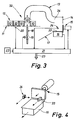
- the device part which is used to discharge and weigh the empty packs.
- the main problem here is the fragility and the low weight of the packs 10.
- the packs 10 arriving on the conveyor belt 11 are held in conveyor cells 12.
- the conveyor cells 12 are provided with an opening at the bottom, the mouth of a blow-out line 18 being attached under the conveyor belt 11 in such a way that the openings in the conveyor cells sweep past the conveyor belt 11 as it runs.
- the blow-out line 18 is connected to a compressed air source, not shown, via a solenoid valve 19.
- the solenoid valve 19 is controlled via an output of the control unit 21.
- the mouth of a conveyor tube 13 is positioned, the cross section of which is essentially adapted to that of the bags 10 to be conveyed.
- the arrangement is thus such that, with the correct positioning of a delivery cell 12 with a bag 10 therein, 18 bags 10 can be blown into the delivery pipe 13 above the mouth of the blow-out line.
- the directed air flow is dimensioned so that a bag blown into the line 13 is conveyed through the line.
- the line 13 runs essentially horizontally and is open at the bottom.
- a baffle plate 14 is attached in the axis of the end section 34, so that packs 10 which reach the end section 34 at a certain conveying speed are braked on the baffle plate 14 and fall down.
- a slide 15 is attached to the scale 16 and can be actuated via an output signal from the control unit 21.
- the slide 15 is arranged in such a way that a package 10 located on the weighing plate 33 of the balance 16 is pushed off the plate 33 when the slide 15 is actuated.
- a discharge chute 17 is attached to the scale 16, onto which a bag 10 pushed by the slide 15 from the plate 33 can fall, in order to then be fed to a waste container.
- the packs 10 can be removed from the plate 33 by blowing air (blowing nozzle - not shown) and conveyed to the waste container.
- a light barrier 24 which is described in more detail below, is attached above the weighing plate 33 and is connected to an input of the control unit 21.
- the way in which the light barrier 24 is attached is such that when a bag 10 lies on the weighing plate 33, the light path of the light barrier 24 is interrupted, so that the presence of a bag 10 on the weighing plate 33 can be detected.
- a light barrier (not shown), which is connected to the control unit 21, is preferably also mounted in the end section 34 of the delivery pipe 13 and via which a jamming of bags in the end section 34 can be detected.
- a belt sensor 20 is provided in the vicinity of the conveyor belt 11, the output signals of which are fed to the control unit 21 in order to synchronize the control of the solenoid valve 19 with the clock rate of the conveyor belt 11.
- the input unit 23, which is connected to an input of the control unit 21, is also shown in FIG. 3 for the sake of completeness.
- the control output 23 of the control unit 21 is also shown in FIG. 3 for the sake of completeness.
- the tare weight that is to say the weight of the empty bags, is plotted upwards, a jump-like change in the tare weight from weight G1 to weight G2 and back to weight G1 being shown to clarify the control behavior.
- the device according to the invention (or via the computer 35) not only carries out this averaging, but also a difference between the two averages G1 and G2 .
- the result of this difference formation is shown in Fig. 5 (c).
- the difference is compared with a threshold value (dashed line in FIG. (C)).
- the mean value is now normally G1 , which was obtained from the larger number of samples, as the tare value of the regulation (see FIG. 2).
- the mean value becomes G2 used as the tare value of the regulation. This fact is shown in Fig. 5 (d) in more detail.
- the resulting curve which represents the tare weight on which the control is based, therefore initially increases in the event of a sudden change in the actual measured values in accordance with the slope of the mean value curve G1 on (between n0 and n1). But as soon as the difference between the two averages G1 and G2 exceeds the threshold, the tare specification changes in accordance with the steeper rise in the mean value curve G2 fast (between n1 and n2), so that the tare value on which the regulation is based is very quickly approximated to the actual value. When the tare value decreases from weight G2 to weight G1, the process is reversed.
- the jumping back and forth between the two mean values results G1 and G2 Fluctuations in the control behavior, which can be seen in FIG. 5 (d) between the times n3 and n4 or n8 and n9.
- such fluctuations can be compensated for by jumping from the mean G1 to the mean G2 abruptly, jumping back from the mean G2 to the mean G1 (when calculating the tare specification) but with a delay.
- the correction value determined in the control unit 21 (or by the computer 35) for the adjustment of the filling machine is preferably fed to this filling machine via a motor-operated potentiometer.
- the motorized potentiometer is preferably used instead of the already manually adjustable potentiometer, with switching means being provided so that the system can be switched over to manual setting if necessary.
Abstract
Description
Die Erfindung betrifft ein Verfahren zum Abfüllen von Schüttgut, insbesondere von Kaffee sowie eine Vorrichtung zur Durchführung des Verfahrens nach dem Oberbegriff des Patentanspruches 1 bzw. 11.11. The invention relates to a method for filling bulk goods, in particular coffee, and a device for carrying out the method according to the preamble of
Bei der Kaffee-Abfüllung in Verpackungen tritt das Problem auf, daß Schwankungen in den im allgemeinen volumetrisch arbeitenden Abfüllungsmaschinen, im Schüttgewicht des Kaffees und im Tara-Gewicht auftreten. Vom Gesetzgeber ist eine exakte Einhaltung des Mittelwertes des Packungsinhaltes gefordert, wobei Überschreitungen des Packungsinhaltes zulässig sind, Unterschreitungen jedoch nicht. Die zulässigen Streuungswerte sind ebenfalls festgelegt.When filling coffee in packaging, the problem arises that fluctuations occur in the generally volumetric filling machines, in the bulk density of the coffee and in the tare weight. Legislators are required to adhere exactly to the mean value of the contents of the package, although exceeding the contents of the package is permissible, but not falling short. The permissible scatter values are also specified.
Um nun die Mindestwerte einzuhalten, füllt man im Mittel mehr Kaffee ein als notwendig.To comply with the minimum values, you fill in more coffee than necessary on average.
Was die Schwankungen betrifft, die durch die Abfüllungsmaschinen oder durch Schwankungen im Schüttgewicht des Kaffees verursacht werden, so sind hier bereits umfangreiche Maßnahmen zur Minimierung der Schwankungen getroffen worden.As far as the fluctuations caused by the filling machines or by fluctuations in the bulk density of the coffee are concerned, extensive measures have already been taken to minimize the fluctuations.
Beim Taragewicht, also dem Gewicht der zu befüllenden Tüten, sind ebenfalls gewisse Schwankungen nicht zu vermeiden, da die Folien, aus welchen die Tüten hergestellt werden, hinsichtlich ihrer Dicke aufgrund der (bekannten) Herstellungsprozesse (Blasen) nur in bestimmten Grenzen konstant sind. Da die Zuschnitte für jede Tüte gleich groß sind, ergeben sich Schwankungen im Taragewicht, die momentan bei etwa 8 % liegen.With the tare weight, i.e. the weight of the bags to be filled, certain fluctuations cannot be avoided either, since the thickness of the films from which the bags are made is only constant within certain limits due to the (known) manufacturing processes (bubbles). Since the cuts are the same for each bag, there are fluctuations in the tare weight, which are currently around 8%.
Selbstverständlich tritt dieselbe Problematik bei allen anderen Schüttgütern ebenfalls auf, wobei das Problem um so schwerer wiegt, je teurer der Packungsinhalt ist.Of course, the same problem also occurs with all other bulk goods, although the more expensive the contents of the package, the more serious the problem.
Aus der US-A-3 073 398 sind Vorrichtung und Verfahren zum Abfüllen von Schüttgut bekannt, bei denen eine laufende Ermittlung des Tara-Gewichtes und Regelung der Einfüllmenge über Vergleich mit einem laufend ermittelten Brutto-Gewicht durchgeführt werden. Das bekannte Verfahren bzw. die bekannte Vorrichtung ermöglichen jedoch nur relativ geringe Durchsatzraten bei hohem apparativen Aufwand, da herkömmliche Waagen nicht mehr verwendbar sind. Insbesondere liegt ein Hauptproblem in der bei so geringen Gewichten (der unbefüllten Tüten) großen Nachschwingzeit der Waagen.From US-A-3 073 398 apparatus and methods for filling bulk goods are known, in which a continuous determination of the tare weight and regulation of the filling quantity are carried out by comparison with a continuously determined gross weight. The known method and the known device, however, only enable relatively low throughput rates with a high expenditure on equipment, since conventional scales can no longer be used. In particular, one of the main problems lies in the long oscillation time of the scales with such low weights (the empty bags).
Ausgehend vom oben genannten Stand der Technik liegt der vorliegenden Erfindung die Aufgabe zugrunde, Verfahren und Vorrichtung der eingangs genannten Art dahingehend weiterzubilden, daß mit geringerem Aufwand als bisher eine hinreichend exakte Netto-Einwaage erzielbar ist.Starting from the above-mentioned prior art, the present invention is based on the object of developing methods and apparatus of the type mentioned at the outset in such a way that a sufficiently exact net weight can be achieved with less effort than previously.
Diese Aufgabe wird durch die im Kennzeichen der Patentansprüche 1 bzw. 11 aufgeführten Merkmale gelöst.This object is achieved by the features listed in the characterizing part of
Dadurch, daß man immer wieder Stichproben nimmt und nicht nur zu Schichtbeginn gelingt es, bei sprungförmigen Schwankungen während des Betriebes Fehler auszumerzen, die bisher toleriert werden mußten. Derartige sprungförmige Schwankungen treten z.B. auf, wenn innerhalb einer Folienrolle eine Nahtstelle auftritt, die von einer Folienbahn zur nächsten Folienbahn (aus einer anderen Charge) überleitet. Überraschenderweise konnte gezeigt werden, daß eine stichprobenweise (aber kontinuierlich) durchgeführte Messung der Tara-Vorgabe zur Sollwerteinstellung in einer geschlossenen Regelschleife verwendbar ist. Hierbei ist es von Vorteil, wenn man eine gleitende Mittelwertsbildung über eine definierte Anzahl von Leerpackungen durchführt.Due to the fact that samples are taken again and again and not only at the beginning of the shift, it is possible to eliminate errors in the event of sudden fluctuations during operation that previously had to be tolerated. Such sudden fluctuations occur e.g. when there is a seam within a film roll that leads from one film web to the next film web (from another batch). Surprisingly, it could be shown that a sample (but continuous) measurement of the tare specification can be used for setting the setpoint in a closed control loop. It is advantageous here to carry out a moving averaging over a defined number of empty packs.
Besonders schnell reagiert die Regelung dann, wenn man die gleitende Mittelwertsbildung in zwei Gruppengrößen, einer größeren und einer kleineren Gruppe, durchführt und den Mittelwert der kleineren Gruppe dann der Regelung zugrundelegt, wenn dieser vom Mittelwert der grösseren Gruppe um mindestens bzw. mehr als einen vorbestimmten Betrag abweicht. Einerseits wird dadurch das Regelverhalten im allgemeinen (wenn also der Mittelwert der kleineren Gruppe innerhalb der zulässigen Schwankungsbreite liegt) nicht unnötig unruhig, andererseits kann dennoch eine schnelle Ausregelung von sprungförmigen Änderungen erfolgen.The control reacts particularly quickly if the moving averaging is carried out in two group sizes, a larger and a smaller group, and the control is based on the average of the smaller group if this is at least or more than a predetermined value from the average of the larger group Amount differs. On the one hand, the control behavior in general (if the mean value of the smaller group within the permissible fluctuation range) ) is not unnecessarily uneasy, on the other hand, a rapid correction of sudden changes can still take place.
Bei der erfindungsgemäßen Vorrichtung führt man vorzugsweise die auszuwiegenden Tüten über eine Blasvorrichtung einer (elektronischen) Waage zu.In the device according to the invention, the bags to be weighed are preferably fed to an (electronic) balance via a blowing device.
Weitere bevorzugte Ausführungsformen der Erfindung ergeben sich aus den Unteransprüchen und den nachfolgenden Ausführungsbeispielen bevorzugter Ausführungsformen der Erfindung, die anhand von Abbildungen näher beschrieben werden. Hierbei zeigen:
- Fig. 1
- ein prinzipielle Darstellung der Gesamtanordnung einer Anlage;
- Fig. 2
- eine prinzipielle Darstellung der Regelschleife;
- Fig. 3
- eine schematisierte Darstellung der Ausschleuse-Vorrichtung;
- Fig. 4
- eine perspektivische Darstellung der Tara-Waage mit Schieber; und
- Fig. 5
- ein Diagramm zur Darstellung des Regelverhaltens.
- Fig. 1
- a schematic representation of the overall arrangement of a system;
- Fig. 2
- a basic representation of the control loop;
- Fig. 3
- a schematic representation of the discharge device;
- Fig. 4
- a perspective view of the tare scale with slide; and
- Fig. 5
- a diagram to illustrate the control behavior.
In Fig. 1 ist eine bevorzugte Ausführungsform einer Abfüllanlage gezeigt. Mit der Bezugsziffer 29 ist eine Maschine zum Herstellen von Tüten bezeichnet, der das Folienmaterial von einem Folienwickel 30 zugeführt wird. Die fertig gefalteten und oben offenen Tüten werden auf einem Förderband 11 gefördert, das die Tüten einer Abfüllmaschine 28 zuführt. Der Abfüllmaschine 28 wird über eine Kaffee-Zuführung 31 Kaffee zugeführt, der in die Tüten eingefüllt werden soll. Das Förderband 11 verläßt die Abfüllmaschine 28 mit den fertig befüllten und verschlossenen Packungen.1 shows a preferred embodiment of a filling system. The
Zwischen der Tütenformermaschine 29 und der Abfüllmaschine 28 ist eine Tütenweiche 32 vorgesehen, deren Ausgestaltung weiter unten näher beschrieben wird. Die Weiche 32 wird von einer Regeleinheit 21 zu bestimmten Zeitpunkten betätigt und zwar derart, daß einzelne Tüten vom Förderband 11 ausgeschleust und über ein Förderrohr 13 eine Tara-Waage 16 zugeführt werden.A
Die Tara-Waage 16 wandelt das Gewicht der Tüte in ein elektrisches Ausgangssignal um, das wiederum der Regeleinheit 21 zugeführt wird. Nach dem Wiegen wird die gewogene Tüte von der Tara-Waage 16 über eine von der Regeleinheit 21 steuerbare Vorrichtung abgeschoben, die weiter unten näher beschrieben ist. Weiterhin ist über der Tara-Waage 16 eine Lichtschranke 24 vorgesehen, über die festgestellt werden kann, ob eine Tüte auf der Tara-Waage 16 liegt bzw. ob die Tüte richtig liegt. Das Ausgangssignal der Lichtschranke 24 wird ebenfalls der Regeleinheit 21 zugeführt.The
Die Anlage ist weiterhin mit einem Bandfühler 20 versehen, über den die Taktrate festgestellt werden kann, mit der die Anlage arbeitet. Dieser Bandfühler 20 dient (unter anderem) zur Synchronisation beim Ausschleus-Vorgang.The system is also provided with a
Nach der Abfüllmaschine 28 ist eine ebenfalls von der Regeleinheit 21 gesteuerte Abzweigweiche 26 zum Ausschleusen gefüllter Packungen vorgesehen. Diese gefüllten Packungen werden über eine (elektronische) Brutto-Waage 25 geleitet und über eine Einschleusweiche 27 dem Förderstrom wieder zugeführt. In der Brutto-Waage 25 wird das Gewicht der gewogenen Packungen in elektrische Signale umgewandelt, die wieder der Regeleinheit 21 zugeführt werden.After the
Mit dem Eingang der Regeleinheit 21 ist weiterhin eine Eingabeeinheit 22 verbunden, über welche Vorgabewerte eingebbar sind.An
Ein Stellausgang 23 ist mit einem Stellorgan der Abfüllmaschine 28 verbunden, wobei die von der Abfüllmaschine 28 eingefüllte Kaffeemenge über das Stellsignal des Stellausganges 23 einstellbar ist.A
Der regeltechnische Zusammenhang wird im folgenden anhand von Fig. 2 näher beschrieben.The control relationship is described in more detail below with reference to FIG. 2.
Über den Fühler 25 (Brutto-Waage) wird das Bruttogewicht der befüllten (und verschlossenen) Packungen gewogen und einem Vergleicher zugeführt. Weiterhin wird dem Vergleicher ein Sollwert zugeführt, der aus dem eigentlichen Sollwert, nämlich dem Packungsinhalt, einer Konstant-Taravorgabe (Leim-Gewicht, Etiketten-Gewicht etc.) und dem Ausgangssignal des Meßfühlers 16 (Tara-Waage) gebildet wird. Die beiden ersteren Werte werden über die Eingabeeinheit 22 eingegeben.The gross weight of the filled (and closed) packages is weighed via the sensor 25 (gross balance) and fed to a comparator. Furthermore, the comparator is supplied with a setpoint, which is formed from the actual setpoint, namely the package contents, a constant tare specification (glue weight, label weight etc.) and the output signal of the sensor 16 (tare scale). The first two values are entered via the
Der Meßfühler 16 (Tara-Waage) sitzt am Ausgang der Tütenformmaschine 29, die der Abfüllmaschine 28 die Tüten zuführt.The sensor 16 (tare scale) sits at the outlet of the
Die Abweichung zwischen gemessenem Bruttowert und Soll-Bruttowert wird einem Rechner 35 zugeführt, der Bestandteil der Regeleinheit 21 ist und ein Ausgangssignal erzeugt, das zur Einstellung der Füllmenge in der Abfüllmaschine 28 dient. Auf diese Weise ist somit eine geschlossene Regelschleife gebildet, die eine konstante Abfüllmenge (Abfüllgewicht) unabhängig von Schwankungen im Taragewicht ermöglicht.The deviation between the measured gross value and the target gross value is fed to a
Im folgenden wird eine bevorzugte Ausführungsform desjenigen Vorrichtungsteiles beschrieben, der zum Ausschleusen und Abwiegen der leeren Packungen dient. Wesentliches Problem hierbei ist die Fragilität und das geringe Gewicht der Packungen 10.In the following, a preferred embodiment of the device part is described which is used to discharge and weigh the empty packs. The main problem here is the fragility and the low weight of the
Die auf dem Förderband 11 ankommenden Packungen 10 werden in Förderzellen 12 gehalten. Die Förderzellen 12 sind nach unten mit einer Öffnung versehen, wobei unter dem Förderband 11 die Mündung einer Ausblasleitung 18 derart angebracht ist, daß die Öffnungen in den Förderzellen beim Laufen des Förderbandes 11 an dieser vorbeistreichen.The
Die Ausblasleitung 18 steht mit einer nicht gezeigten Druckluftquelle über ein Magnetventil 19 in Verbindung. Das Magnetventil 19 wird über einen Ausgang der Regeleinheit 21 angesteuert.The blow-
Über dem Förderband 11 bzw. den Förderzellen 12 ist die Mündung eines Förderrohres 13 positioniert, dessen Querschnitt im wesentlichen dem der zu fördernden Tüten 10 angepaßt ist. Die Anordnung ist also derart getroffen, daß bei korrekter Positionierung einer Förderzelle 12 mit darin befindlicher Tüte 10 über der Mündung der Ausblasleitung 18 Tüten 10 in das Förderrohr 13 eingeblasen werden können. Der gerichtete Luftstrom wird hierbei so bemessen, daß eine in die Leitung 13 geblasene Tüte durch die Leitung hindurch gefördert wird.Above the
In ihrem Endabschnitt 34 verläuft die Leitung 13 im wesentlichen horizontal und ist nach unten offen. In der Achse des Endabschnittes 34 ist ein Prallblech 14 angebracht, so daß Packungen 10, die mit einer gewissen Fördergeschwindigkeit in den Endabschnitt 34 gelangen, am Prallblech 14 abgebremst werden und nach unten fallen.In its
Unterhalb des Endabschnittes 34 der Rohrleitung 13 ist eine Tara-Waage 16 so angebracht, daß herabfallende Tüten 10 auf den Wägeteller 33 der Waage 16 fallen. Vorzugsweise ist die Waage 16 als elektronische Waage ausgebildet, die sich immer wieder selbsttätig (im unbelasteten Zustand) abgleicht. Ihr Ausgang ist auf einen Eingang der Regeleinheit 21 geführt.Below the
Bei der Waage 16 ist ein Schieber 15 angebracht, der über ein Ausgangssignal der Regeleinheit 21 betätigbar ist. Der Schieber 15 ist hierbei derart angeordnet, daß eine auf dem Wägeteller 33 der Waage 16 befindliche Packung 10 bei Betätigung des Schiebers 15 vom Teller 33 geschoben wird. Weiterhin ist bei der Waage 16 eine Abfuhrrutsche 17 angebracht, auf die eine durch den Schieber 15 vom Teller 33 geschobene Tüte 10 fallen kann, um dann einem Abfallbehälter zugeführt zu werden.A
Statt durch den Schieber 15 können die Packungen 1o durch Blasluft (Blasdüse - nicht dargestellt) vom Teller 33 ab-und dem Abfallbehälter zugefördert werden.Instead of using the
Weiterhin ist oberhalb des Wägetellers 33 eine Lichtschranke 24, die weiter unten näher beschrieben wird, angebracht, die mit einem Eingang der Regeleinheit 21 in Verbindung steht. Die Anbringungsweise der Lichtschranke 24 (siehe Fig. 4) ist hierbei derart, daß dann, wenn eine Tüte 10 auf dem Wägeteller 33 liegt, der Lichtweg der Lichtschranke 24 unterbrochen wird, so daß die Anwesenheit einer Tüte 10 auf dem Wägeteller 33 detektierbar ist.Furthermore, a
Vorzugsweise ist im Endabschnitt 34 des Förderrohres 13 ebenfalls eine Lichtschranke (nicht gezeigt) angebracht, die mit der Regeleinheit 21 in Verbindung steht und über die ein Verklemmen von Tüten im Endabschnitt 34 detektierbar ist.A light barrier (not shown), which is connected to the
Es ist ein Bandfühler 20 in der Nähe des Förderbandes 11 vorgesehen, dessen Ausgangssignale der Regeleinheit 21 zugeführt werden, um die Ansteuerung des Magnetventiles 19 mit der Taktrate des Förderbandes 11 zu synchronisieren.A
Die Eingabeeinheit 23, die mit einem Eingang der Regeleinheit 21 in Verbindung steht, ist in Fig. 3 der Vollständigkeit halber ebenfalls angegeben. Der Stellausgang 23 der Regeleinheit 21 ist in Fig. 3 der Vollständigkeit halber ebenfalls angegeben.The
Im folgenden wird die erfindungsgemäße Verfahrensweise, die sich mit der oben beschriebenen Vorrichtung durchführen läßt, anhand der Fig. 5 näher beschrieben. In dieser Abbildung ist nach rechts die Anzahl der Tüten bzw. bei konstanter Fördergeschwindigkeit des Bandes 11 die Zeit aufgetragen.The procedure according to the invention, which can be carried out with the device described above, is described in more detail below with reference to FIG. 5. In this figure, the number of bags or, if the
In Fig. 5 (a) ist nach oben das Taragewicht, also das Gewicht der leeren Tüten aufgetragen, wobei zur Verdeutlichung des Regelverhaltens eine sprungförmige Änderung des Taragewichtes vom Gewicht G1 zum Gewicht G2 und wieder zurück zum Gewicht G1 gezeigt ist.5 (a), the tare weight, that is to say the weight of the empty bags, is plotted upwards, a jump-like change in the tare weight from weight G1 to weight G2 and back to weight G1 being shown to clarify the control behavior.
Wenn man nun zwei (gleitende) Mittelwerte
Mit der erfindungsgemäßen Vorrichtung (bzw. über den Rechner 35) wird nicht nur diese Mittelwertsbildung durchgeführt, sondern auch eine Differenzbildung zwischen den beiden Mittelwerten
Bei der hier gezeigten, sehr einfachen Ausführungsform der Erfindung ergeben sich durch das Hin- und Herspringen zwischen den beiden Mittelwerten
Überraschenderweise hat es sich gezeigt, daß man mit dem erfindungsgemäßen Verfahren ausgezeichnete Ausregelungen von Schwankungen des Taragewichtes aufgrund von Schwankungen der Folienstärke erzielen kann. Es genügt hierbei eine Bruttogewichtsmessung von 10 % durchzuführen, während die Taragewichtsbestimmung bei nur 0,75 % der leeren Tüten durchgeführt wird. Dadurch, daß die leeren Tüten verworfen werden, kann die Taktrate der Vorrichtung wesentlich gesteigert werden, es ist nämlich nicht notwendig, die fragilen leeren Tüten wieder in den Prozeß einzuschleusen. Nachdem aber nur 0,75 % der leeren Tüten verworfen werden, hält sich der Verlust in durchaus tragbaren Grenzen.Surprisingly, it has been found that excellent adjustments of fluctuations in the tare weight due to fluctuations in the film thickness can be achieved with the method according to the invention. It is sufficient to carry out a gross weight measurement of 10%, while the tare weight determination is carried out with only 0.75% of the empty bags. By discarding the empty bags, the clock rate of the device can be increased significantly, because it is not necessary to re-insert the fragile empty bags into the process. However, after only 0.75% of the empty bags are discarded, the loss is within reasonable limits.
Vorzugsweise wird der in der Regeleinheit 21 (bzw. vom Rechner 35) ermittelte Korrekturwert für die Verstellung der Befüllungsmaschine über ein motorisch betriebenes Potentiometer dieser Befüllungsmaschine zugeführt. Das motorisch betriebene Potentiometer wird vorzugsweise anstelle des ohnehin hand-einstellbaren Potentiometers verwendet, wobei Umschaltmittel vorgesehen sind, so daß die Anlage im Bedarfsfall auf Handeinstellung umgeschaltet werden kann.The correction value determined in the control unit 21 (or by the computer 35) for the adjustment of the filling machine is preferably fed to this filling machine via a motor-operated potentiometer. The motorized potentiometer is preferably used instead of the already manually adjustable potentiometer, with switching means being provided so that the system can be switched over to manual setting if necessary.
Weiterhin werden vorzugsweise alle Einzelmessungen von Tara- und Bruttogewicht mit dem momentanen Mittelwert verglichen und dann verworfen, also der weiteren Mittelwertsbildung nicht zugrunde gelegt, wenn sie mehr als einen vorbestimmten Betrag vom momentanen Mittelwert abweichen. Dadurch führen "Ausreißer" nicht zu einem ungewollten Regelvorgang.Furthermore, all individual measurements of tare weight and gross weight are preferably compared with the current mean value and then discarded, that is, they are not used as the basis for further averaging if they are more than deviate from the current mean by a predetermined amount. As a result, "outliers" do not lead to an unwanted control process.
Weiterhin wird vorzugsweise das Meßergebnis aus allen Tara- und Bruttomessungen gespeichert und dokumentiert. Diese Dokumentation kann dann zu Kontrollzwecken (durch den Anwender oder auch durch die staatlichen Aufsichtsorgane) herangezogen werden. Dies ist ein weiterer, ganz wesentlicher Vorteil der vorliegenden Erfindung, der bisher nicht gegeben war.Furthermore, the measurement result from all tare and gross measurements is preferably saved and documented. This documentation can then be used for control purposes (by the user or by the state supervisory bodies). This is a further, very essential advantage of the present invention, which has not previously existed.
Wenn man die mit der erfindungsgemäßen Vorrichtung bzw. mit dem erfindungsgemäßen Verfahren erzielbare Einwiegegenauigkeit mit der bisher möglichen Einwiegegenauigkeit vergleicht, so werden die Vorteile der vorliegenden Erfindung ganz offensichtlich: Bisher muß man im Mittel anstelle der geforderten 500 g Einwaage 501 g einfüllen, damit die zulässigen Mittelwerte und Streuungswerte sicher eingehalten werden. Nachdem das Taragewicht 19 g beträgt und die Schwankungen (wie oben angegeben) bei etwa 8 %, also bei 1,5 g pro Packung liegen, kann man bei Anwendung der vorliegenden Erfindung auf eine Einwaage von ca. 500,1 bis 500,2 g kommen. Der Aufwand hierfür ist sowohl verfahrens- als auch vorrichtungsmäßig äußerst gering.If one compares the weighing accuracy achievable with the device according to the invention or with the method according to the invention with the weighing accuracy that has been possible up to now, the advantages of the present invention become quite obvious: up to now, instead of the required 500 g sample weight, 501 g have to be filled in so that the permissible Average values and scatter values are reliably observed. After the tare weight is 19 g and the fluctuations (as stated above) are around 8%, ie 1.5 g per pack, the present invention can be used to weigh approximately 500.1 to 500.2 g come. The effort for this is extremely low in terms of both method and device.
Claims (21)
- Method of packaging fluent solid material, in particular coffee in packets, with the filling quantity of a filling machine being set in accordance with the gross weight of filled packets and a tare allowance, characterised in that the tare allowance, taking into account the weight of the empty packaging, is determined by random sampling and the value of the gross weight determined less the value of the tare weight determined and less a constant tare allowance, taking into account constant weight components such as glue weight, label weight or the like, is fed to the filling machine as a nominal value in a closed control loop.
- Method according to Claim 1, characterised in that the tare allowance is determined by weighing out empty packets by random sampling.
- Method according to Claim 2, characterised in that the random sampling is carried out at regular intervals.
- Method according to one of the preceding claims, characterised in that an average is taken over several random samples and the average value is taken as a basis for the control.
- Method according to Claim 4, characterised in that a sliding average value is formed over a defined number of empty packets.
- Method according to Claim 5, characterised in that the value of an individual random sample which deviates from the instantaneous average value by more than a predetermined maximum amount is rejected without using it in further average value formation.
- Method according to one of Claims 5 or 6, characterised in that the sliding average value is formed in two group sizes - a larger and a smaller group - and the average value of the smaller group is then (and only then) taken as a basis for the control if it deviates from the average value of the larger group by at least a predetermined amount.
- Method according to one of the preceding claims, characterised in that the gross weight is determined by random sampling.
- Method according to Claim 8, characterised in that the gross random samples are taken more frequently than the tare random samples.
- Method according to one of the preceding claims, characterised in that the weighed empty packets are rejected.
- Apparatus for packaging fluent solid material, in particular coffee, comprising a bag forming machine (29) for producing bags (10) to be filled, with a tare balance (16) for weighing bags to be filled, a filling machine (28) for filling the bags (10) with the fluent solid material, with a gross balance (25) for weighing the filled bags (10), and a conveyor belt (11) for conveying the bags (10), characterised by means (switch 32) for filtering out empty bags (10) from the conveyor belt (11), conveying means (conveying tube 13) for conveying the filtered-out bags to the tare balance (16), a device (22) for inputting a constant tare allowance, taking into account constant weight components such as glue weight, label weight or the like, and by a control unit (21) which is connected on the input side via signal lines to the measuring outputs of the tare balance (16) and the gross balance (25), and its regulating output (23) is connected in such a controlling manner to the filling machine (28) and the means (32) for filtering out the empty bags that empty bags (10) are filtered out and weighed at a defined frequency, and the filling machine (28), with regard to the filling quantity, is set in accordance with the value of the gross weight determined less the value of the tare weight determined and the constant tare allowance.
- Apparatus according to Claim 11, characterised in that the switch (32) for filtering out the empty bags (10) comprises a blast apparatus (18) with a controllable valve (19).
- Apparatus according to Claim 12, characterised in that the conveyor belt (11) includes passage openings at which the blast apparatus (18) is attached in such a way that the bags (10) can be blown upwards out of the conveying flow.
- Apparatus according to one of Claims 11 to 13, characterised in that the conveying means (13) for conveying the filtered-out bags (10) terminate at a defined distance above the tare balance (16) so that the filtered-out bags (10) fall onto a weighing plate (33) of the tare balance (16).
- Apparatus according to Claim 14, characterised in that a discharge device (15) which can be actuated by the control unit (21) is attached above the weighing plate (33) of the tare balance (16) in such a way that bags lying on the weighing plate (33) can be fed to an exit shute (17).
- Apparatus according to one of Claims 14 or 15, characterised in that a detector apparatus (light barrier 24) which is connected to an input of the control unit (21) and is intended for establishing the presence of bags (10) on the weighing plate (33) is arranged above the weighing plate (33).
- Apparatus according to one of Claims 12 to 16, characterised in that the conveying means (13) for conveying the filtered-out bags (10) is designed as a tube line.
- Apparatus according to Claim 17, characterised in that the tube line (13) runs essentially horizontally in its end section (34), and that a baffle plate (14) is attached above the weighing plate (33) perpendicularly to the tube or conveyor direction in such a way that the conveyed bags (10) are slowed down on the baffle plate (14) and fall down onto the weighing plate (33).
- Apparatus according to Claim 15, characterised in that the bags (10) can be discharged from the tare balance (16) by a blast apparatus (blast nozzle) by means of an air blast.
- Apparatus according to one of Claims 11 to 19, characterised in that the control unit (28) (sic) is connected on the input side to an input unit (22) via which the (further) tare allowances can be fed in.
- Apparatus according to one of Claims 11 to 20, characterised in that the control unit (21) comprises a computer (35).
Priority Applications (1)
| Application Number | Priority Date | Filing Date | Title |
|---|---|---|---|
| AT87118218T ATE73072T1 (en) | 1986-12-30 | 1987-12-09 | METHOD AND DEVICE FOR FILLING BULK PRODUCTS, ESPECIALLY COFFEE. |
Applications Claiming Priority (2)
| Application Number | Priority Date | Filing Date | Title |
|---|---|---|---|
| DE19863644713 DE3644713A1 (en) | 1986-12-30 | 1986-12-30 | METHOD AND DEVICE FOR FILLING GOODS, IN PARTICULAR COFFEE |
| DE3644713 | 1986-12-30 |
Publications (3)
| Publication Number | Publication Date |
|---|---|
| EP0273254A2 EP0273254A2 (en) | 1988-07-06 |
| EP0273254A3 EP0273254A3 (en) | 1989-11-08 |
| EP0273254B1 true EP0273254B1 (en) | 1992-03-04 |
Family
ID=6317378
Family Applications (1)
| Application Number | Title | Priority Date | Filing Date |
|---|---|---|---|
| EP87118218A Expired - Lifetime EP0273254B1 (en) | 1986-12-30 | 1987-12-09 | Method and device for pouring bulk material, especially coffee |
Country Status (7)
| Country | Link |
|---|---|
| US (1) | US4890441A (en) |
| EP (1) | EP0273254B1 (en) |
| JP (1) | JPH0758220B2 (en) |
| AT (1) | ATE73072T1 (en) |
| CA (1) | CA1310576C (en) |
| DE (2) | DE3644713A1 (en) |
| ES (1) | ES2030420T3 (en) |
Families Citing this family (5)
| Publication number | Priority date | Publication date | Assignee | Title |
|---|---|---|---|---|
| DE69317852T2 (en) * | 1992-05-15 | 1998-08-20 | Ishida Scale Mfg Co Ltd | Partial quantity scales with tare allowance for a packaged product. |
| IT1258025B (en) * | 1992-07-31 | 1996-02-20 | Mg 2 Spa | METHOD AND DEVICE FOR THE DOSAGE OF A PHARMACEUTICAL PRODUCT INSIDE CAPSULES |
| US5806287A (en) * | 1997-04-21 | 1998-09-15 | Dimension Automation, Inc. | On-the-go check weigh system |
| US20070011993A1 (en) * | 2005-07-18 | 2007-01-18 | Jack Salvatore Mannoia | Method and system for manufacturing adhesive packets |
| DE102020128350A1 (en) | 2020-10-28 | 2022-04-28 | Wipotec Gmbh | Method and device for zeroing a balance |
Family Cites Families (7)
| Publication number | Priority date | Publication date | Assignee | Title |
|---|---|---|---|---|
| US3073398A (en) * | 1956-03-27 | 1963-01-15 | Foils Packaging Corp | Automatic weighing and packaging apparatus |
| US3684875A (en) * | 1970-09-28 | 1972-08-15 | Wm Ainsworth Inc | Analog-to-digital measuring apparatus |
| DE2323750B2 (en) * | 1973-05-10 | 1975-11-13 | Atoma Gmbh, 8264 Waldkraiburg | Weighing device for continuous weighing |
| DE2532105A1 (en) * | 1974-07-19 | 1976-02-26 | Telomex Horsham Ltd | Control device for manufacture of articles - on production line measures parameter of articles coming off line and feeds back data |
| US4049068A (en) * | 1976-05-03 | 1977-09-20 | Hi-Speed Checkweigher Co., Inc. | Price labeling system with floating zero reference |
| US4582150A (en) * | 1984-06-21 | 1986-04-15 | Taylor Products Co., Inc. | Automated, integrated, filling, check weighing, and self-correcting bagging apparatus and method |
| CH667922A5 (en) * | 1985-10-18 | 1988-11-15 | Mettler Instrumente Ag | ELECTRIC SCALE WITH BALANCE DEVICE. |
-
1986
- 1986-12-30 DE DE19863644713 patent/DE3644713A1/en not_active Withdrawn
-
1987
- 1987-12-09 AT AT87118218T patent/ATE73072T1/en not_active IP Right Cessation
- 1987-12-09 ES ES198787118218T patent/ES2030420T3/en not_active Expired - Lifetime
- 1987-12-09 DE DE8787118218T patent/DE3777120D1/en not_active Expired - Fee Related
- 1987-12-09 EP EP87118218A patent/EP0273254B1/en not_active Expired - Lifetime
- 1987-12-15 US US07/133,297 patent/US4890441A/en not_active Expired - Lifetime
- 1987-12-21 CA CA000554966A patent/CA1310576C/en not_active Expired - Fee Related
- 1987-12-29 JP JP62336740A patent/JPH0758220B2/en not_active Expired - Lifetime
Also Published As
| Publication number | Publication date |
|---|---|
| ATE73072T1 (en) | 1992-03-15 |
| JPH0758220B2 (en) | 1995-06-21 |
| ES2030420T3 (en) | 1992-11-01 |
| JPS63173925A (en) | 1988-07-18 |
| EP0273254A2 (en) | 1988-07-06 |
| EP0273254A3 (en) | 1989-11-08 |
| US4890441A (en) | 1990-01-02 |
| CA1310576C (en) | 1992-11-24 |
| DE3777120D1 (en) | 1992-04-09 |
| DE3644713A1 (en) | 1988-07-14 |
Similar Documents
| Publication | Publication Date | Title |
|---|---|---|
| EP0505618B1 (en) | Process and device for determining the mass flow rate removed by an extruder out of a feed hopper | |
| EP0394869B1 (en) | Method for controlling the level of a mixture consisting of at least two components of fluid material in a container with an outlet | |
| EP0215080A1 (en) | Apparatus for automatic registration of a continuous bulk material flow by means of a run-through weighing device. | |
| EP2621814B1 (en) | Apparatus and method for dosing a bulk good | |
| DE19718455A1 (en) | Dispensing appts. for dispensing ground coffee into coffee packages | |
| WO2011069578A1 (en) | Device and method for metering planar products | |
| EP2664551A1 (en) | Method for optimised separation and dispensing of small pharmaceutical products | |
| DE102009043445A1 (en) | Device for dosing powdery or granular materials in capsules or the like | |
| EP2359704B1 (en) | Device and method for bringing together mass flows, in particular for an emptying cartridge | |
| EP1952706A1 (en) | Emptying magazine and method for emptying trays filled with rod-shaped objects, in particular shaft trays | |
| DE102011101045A1 (en) | Packing machine and method for filling open bags | |
| DE4447051A1 (en) | Dispensing feeder with gravimetric or volumetric measurement for delivery of portions of dry, bulk goods | |
| DE102009052292B3 (en) | Device for counting objects supplied as bulk material | |
| EP0273254B1 (en) | Method and device for pouring bulk material, especially coffee | |
| DE19939042A1 (en) | Plastic granulate compound preparation prior to feeding a processing machine, uses a combined material mixing and weighing unit | |
| EP1149196B2 (en) | Mixing fibrous constituents | |
| DE3303766C2 (en) | ||
| EP0095095A1 (en) | Process for weighing bulk material, and weighing device | |
| DE102010003814B4 (en) | Method for automatic dosing and dosing device | |
| DE202005012736U1 (en) | Assembly to control a mixture of raw material components, for delivery to an extruder, has a belt weighing station with a weight sensor to carry feeds from a supply for one component and a volumetric dosing unit for other components | |
| WO1983004306A1 (en) | Method for weighing bulk material and weighing device | |
| EP1135293B1 (en) | Method and device for filling containers | |
| EP0599047B1 (en) | Process for determining the mass flow rate removed by an extruder out of a feed hopper | |
| DE102021129497B3 (en) | Weighing and conveying device and method for conveying and recording the mass flow rate of bulk material | |
| DE2062343A1 (en) | Method and device for cutting and then drying tobacco |
Legal Events
| Date | Code | Title | Description |
|---|---|---|---|
| PUAI | Public reference made under article 153(3) epc to a published international application that has entered the european phase |
Free format text: ORIGINAL CODE: 0009012 |
|
| AK | Designated contracting states |
Kind code of ref document: A2 Designated state(s): AT BE CH DE ES FR GB IT LI NL |
|
| PUAL | Search report despatched |
Free format text: ORIGINAL CODE: 0009013 |
|
| AK | Designated contracting states |
Kind code of ref document: A3 Designated state(s): AT BE CH DE ES FR GB IT LI NL |
|
| 17P | Request for examination filed |
Effective date: 19900307 |
|
| 17Q | First examination report despatched |
Effective date: 19901001 |
|
| GRAA | (expected) grant |
Free format text: ORIGINAL CODE: 0009210 |
|
| AK | Designated contracting states |
Kind code of ref document: B1 Designated state(s): AT BE CH DE ES FR GB IT LI NL |
|
| REF | Corresponds to: |
Ref document number: 73072 Country of ref document: AT Date of ref document: 19920315 Kind code of ref document: T |
|
| GBT | Gb: translation of ep patent filed (gb section 77(6)(a)/1977) | ||
| REF | Corresponds to: |
Ref document number: 3777120 Country of ref document: DE Date of ref document: 19920409 |
|
| ITF | It: translation for a ep patent filed |
Owner name: STUDIO JAUMANN |
|
| ET | Fr: translation filed | ||
| REG | Reference to a national code |
Ref country code: ES Ref legal event code: FG2A Ref document number: 2030420 Country of ref document: ES Kind code of ref document: T3 |
|
| PLBE | No opposition filed within time limit |
Free format text: ORIGINAL CODE: 0009261 |
|
| STAA | Information on the status of an ep patent application or granted ep patent |
Free format text: STATUS: NO OPPOSITION FILED WITHIN TIME LIMIT |
|
| 26N | No opposition filed | ||
| PGFP | Annual fee paid to national office [announced via postgrant information from national office to epo] |
Ref country code: GB Payment date: 20001206 Year of fee payment: 14 |
|
| PGFP | Annual fee paid to national office [announced via postgrant information from national office to epo] |
Ref country code: FR Payment date: 20001212 Year of fee payment: 14 |
|
| PGFP | Annual fee paid to national office [announced via postgrant information from national office to epo] |
Ref country code: AT Payment date: 20001213 Year of fee payment: 14 |
|
| PGFP | Annual fee paid to national office [announced via postgrant information from national office to epo] |
Ref country code: CH Payment date: 20001215 Year of fee payment: 14 |
|
| PGFP | Annual fee paid to national office [announced via postgrant information from national office to epo] |
Ref country code: DE Payment date: 20001216 Year of fee payment: 14 |
|
| PGFP | Annual fee paid to national office [announced via postgrant information from national office to epo] |
Ref country code: ES Payment date: 20001220 Year of fee payment: 14 |
|
| PGFP | Annual fee paid to national office [announced via postgrant information from national office to epo] |
Ref country code: NL Payment date: 20001231 Year of fee payment: 14 |
|
| PGFP | Annual fee paid to national office [announced via postgrant information from national office to epo] |
Ref country code: BE Payment date: 20010315 Year of fee payment: 14 |
|
| PG25 | Lapsed in a contracting state [announced via postgrant information from national office to epo] |
Ref country code: GB Free format text: LAPSE BECAUSE OF NON-PAYMENT OF DUE FEES Effective date: 20011209 Ref country code: AT Free format text: LAPSE BECAUSE OF NON-PAYMENT OF DUE FEES Effective date: 20011209 |
|
| PG25 | Lapsed in a contracting state [announced via postgrant information from national office to epo] |
Ref country code: LI Free format text: LAPSE BECAUSE OF NON-PAYMENT OF DUE FEES Effective date: 20011231 Ref country code: CH Free format text: LAPSE BECAUSE OF NON-PAYMENT OF DUE FEES Effective date: 20011231 Ref country code: BE Free format text: LAPSE BECAUSE OF NON-PAYMENT OF DUE FEES Effective date: 20011231 |
|
| REG | Reference to a national code |
Ref country code: GB Ref legal event code: IF02 |
|
| BERE | Be: lapsed |
Owner name: JACOBS SUCHARD G.M.B.H. Effective date: 20011231 |
|
| PG25 | Lapsed in a contracting state [announced via postgrant information from national office to epo] |
Ref country code: NL Free format text: LAPSE BECAUSE OF NON-PAYMENT OF DUE FEES Effective date: 20020701 |
|
| PG25 | Lapsed in a contracting state [announced via postgrant information from national office to epo] |
Ref country code: DE Free format text: LAPSE BECAUSE OF NON-PAYMENT OF DUE FEES Effective date: 20020702 |
|
| GBPC | Gb: european patent ceased through non-payment of renewal fee |
Effective date: 20011209 |
|
| REG | Reference to a national code |
Ref country code: CH Ref legal event code: PL |
|
| PG25 | Lapsed in a contracting state [announced via postgrant information from national office to epo] |
Ref country code: FR Free format text: LAPSE BECAUSE OF NON-PAYMENT OF DUE FEES Effective date: 20020830 |
|
| NLV4 | Nl: lapsed or anulled due to non-payment of the annual fee |
Effective date: 20020701 |
|
| REG | Reference to a national code |
Ref country code: FR Ref legal event code: ST |
|
| PG25 | Lapsed in a contracting state [announced via postgrant information from national office to epo] |
Ref country code: ES Free format text: LAPSE BECAUSE OF NON-PAYMENT OF DUE FEES Effective date: 20021210 |
|
| REG | Reference to a national code |
Ref country code: ES Ref legal event code: FD2A Effective date: 20030113 |
|
| PG25 | Lapsed in a contracting state [announced via postgrant information from national office to epo] |
Ref country code: IT Free format text: LAPSE BECAUSE OF NON-PAYMENT OF DUE FEES Effective date: 20051209 |