EP0273200A1 - Vorrichtung zum Schneiden von Platten - Google Patents
Vorrichtung zum Schneiden von Platten Download PDFInfo
- Publication number
- EP0273200A1 EP0273200A1 EP87117388A EP87117388A EP0273200A1 EP 0273200 A1 EP0273200 A1 EP 0273200A1 EP 87117388 A EP87117388 A EP 87117388A EP 87117388 A EP87117388 A EP 87117388A EP 0273200 A1 EP0273200 A1 EP 0273200A1
- Authority
- EP
- European Patent Office
- Prior art keywords
- saw
- cutting
- discs
- cut
- carriage
- Prior art date
- Legal status (The legal status is an assumption and is not a legal conclusion. Google has not performed a legal analysis and makes no representation as to the accuracy of the status listed.)
- Granted
Links
Images

Classifications
-
- B—PERFORMING OPERATIONS; TRANSPORTING
- B27—WORKING OR PRESERVING WOOD OR SIMILAR MATERIAL; NAILING OR STAPLING MACHINES IN GENERAL
- B27B—SAWS FOR WOOD OR SIMILAR MATERIAL; COMPONENTS OR ACCESSORIES THEREFOR
- B27B5/00—Sawing machines working with circular or cylindrical saw blades; Components or equipment therefor
- B27B5/29—Details; Component parts; Accessories
- B27B5/30—Details; Component parts; Accessories for mounting or securing saw blades or saw spindles
- B27B5/34—Devices for securing a plurality of circular saw blades on a single saw spindle; Equipment for adjusting the mutual distance
-
- B—PERFORMING OPERATIONS; TRANSPORTING
- B27—WORKING OR PRESERVING WOOD OR SIMILAR MATERIAL; NAILING OR STAPLING MACHINES IN GENERAL
- B27G—ACCESSORY MACHINES OR APPARATUS FOR WORKING WOOD OR SIMILAR MATERIALS; TOOLS FOR WORKING WOOD OR SIMILAR MATERIALS; SAFETY DEVICES FOR WOOD WORKING MACHINES OR TOOLS
- B27G19/00—Safety guards or devices specially adapted for wood saws; Auxiliary devices facilitating proper operation of wood saws
- B27G19/10—Measures preventing splintering of sawn portions of wood
Definitions
- the present invention relates to an apparatus for cutting panels or packs of panels, of wood, plastics material, or similar materials, by means of a cutting carriage comprising a circular saw and means for rotatively actuating said saw, said carriage being movable in either directions along a cutting line with respect to a worktable whereon the panel or pack of panels to be cut is supported, means being provided to adjust the position of said saw normally to said table, whereby during a forward stroke of the cutting carriage is effected a first cut by which said circular saw only partially penetrates the thickness of the panel or pack of panels, and during the return stroke of the cutting carriage is effected a second cut by which said saw completes the first cut by penetrating throughout the thickness of the panel or pack of panels.
- the machines of this type are known, for example, from the Italian Patent Application 12532 A/85.
- the saw is formed by a single saw-disc and the first cut, performed during the forward stroke of the cutting carriage, has the same width as the second cut which is performed during the return stroke of the cutting carriage.
- the saw may engage the edges of the slit created by the first cut, with resulting splintering of these edges.
- This invention aims to eliminate these disadvantages and to provide a machine of the type described in the preamble, wherein the splintering of the edges of the slit created by the first cut is avoided.
- the saw is formed by at least two co-axial, parallel saw discs which may be displaced axially with respect to each other so as to vary the total width of the peripheral cutting edge of the saw, remotely-controlled adjustment means being provided to adjust the width of the cutting edge of the saw during the forward stroke of the cutting carriage to a higher value than the width of the cutting edge of the saw during the return stroke of the cutting carriage, so as to obtain a first cut which is wider than the second cut.
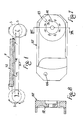
- the cutting apparatus utilizes a circular saw S which cuts a pack of panels or a single panel P in two steps, i.e. through a portion T1 of its thickness during the forward or rightward stroke A, and through the remaining portion T2 during the return or leftward stroke R, the axis of rotation of saw S remaining at all times below or above said material P.
- the direction of rotation of the saw S and the direction of its teeth are such that the surfaces of the lower face and upper face of the material P to be cut, and the surfaces of the two sides of said material, acted upon successively during the forward and backward strokes of said saw and, possibly, during supplementary strokes thereof, will be submitted to compressive forces inwards of said material P, so as to avoid the formation of splinters or other defects on the cut edges.
- the circular saw S is composed of two side-by-side co-axial saw discs or blades having the same characteristics and the mutual spacing of which may be adjusted, through servo-controls, with self-centering and symmetric displacements, whereby the assembly of said saw discs may effect a cut of variable width depending upon a remote control, which may be easily automated with limit-sensors.
- the latter effects a cut T1 having a longitudinal axis aligned therewith, whereby during the execution of the cut T2, the assembly of the saw discs will not interfere with the sides of the cut T1 and, therefore, will not cause the formation of any splinters as, contrarily, occurs in the previous art.
- the numerals 1, 101 indicate the two saw discs having usually the same characteristics and size, axially in line with each other, closely spaced from each other and so that the teeth of one saw disc are disposed intermediately of the interval existing between two consecutive teeth of the adjacent saw disc.
- a limit condition it may be provided that the bodies of the two saw discs 1, 101 be in contact with each other when said saw discs are in their most approached condition, but it is to be understood that this condition is not a limiting or strictly required condition.
- the inner or opposite sides of the teeth of said saw discs may be co-planar with the corresponding inner face of said saw discs, so that the teeth of the two saw discs need not be staggered from each other.
- the saw discs 1, 101 may have teeth of different characteristics though having the same diameter, or that they may have slightly different outer diameters.
- the teeth of the two saw discs 1, 101 protrude by the same extent from both sides of the body of said saw discs, whereby in both conditions of maximum and minimum spacing between said saw discs there will be no void space in the transverse direction, so that the cuts effected by the composite saw 1, 101 will be exempt from intermediate scraps.
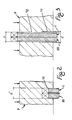
- said saw discs 1, 101 are secured by means of screws 2, 102 to the flanges 3, 103 which, through bearings 4, 104, are rotatably mounted on hubs 5, 105 which are fixed perpendicularly, by means of screws 6, 106, on parallel arms 7, 107 which connect said hubs in cantilever fashion to a supporting structure to be described below.
- the inner race of one 4 of the bearings acts as a guiding and centering means for the free end of the hub 105.
- each saw disc is also characterized in that it is provided with holes 11, 111 receiving, in staggered fashion, the screws 2, 102 to secure said saws to the flanges 3, 103, whereby said saw-discs will be arranged as close as possible to each other so that their bodies will engage, or substantially engage, with each other.
- said arms 7, 107 are constituted by ribbed plates arranged edgewise and provided, on their inner sides, at their ends opposite to those supporting the saw discs, with round and co-axial hubs 12, 112 sealingly receiving thereon round-section sleeves 14, 114, the latter being fixed thereto at one of their ends by means of screws 13, 113 and being slidably telescoped together.
- a cylindrical member 15 is axially slidably arranged within the sleeve 114.
- Said sleeves 14, 114 are formed longitudinally with equal slots 16, 116 the longitudinal central axis of which is located on an imaginary horizontal plane containing the axis of said sleeves, and the horizontal sides of which are located on other imaginary planes which are parallel and equally spaced from the first-mentioned imaginary plane.
- Arranged in said slots are members 17, 117 which are firmly secured to the member 15 by means of screws 18 and which are so shaped as to firmly clamp said member 15.
- said member 15 may be formed with flats for contacting flat ends of the members 17, 117, and it is also to be understood that said flats may be of any shape.
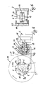
- a shield or guard 19 is fixed to the end of said member 17 that protrudes from the sleeve 14, to prevent dust and chips from entering the slots 16, 116.
- the member 117 is secured in a conventional and adjustable manner to the structure of the powered saw-carrying carriage C which, under command, drives the saw S along the forward and backward strokes discussed above with reference to figure 1.
- the constructional details of said saw-carrying carriage C may be found in the patent application mentioned in the introductory part of this specification.
- said slots 16, 116 are in contact with the members 17, 117 only at the ends thereof, so as to facilitate the sliding movement of said sleeves 14, 114 on said members 17, 117 for the displacement permitted by the length of said slots, which is suitably larger than the width of said members 17, 117.
- annular seals 20, 120 mounted at the ends of said member 15 are respective annular seals 20, 120 the outer faces of which sealingly co-operate with the facing end surfaces of the sleeve 114 which, in turn, is provided exteriorly, in front of the arm 7, with a further annular seal 21 the outer face of which sealingly co-operates with the inner face of the sleeve 14, so as to form at the base of each sleeve, around the respective hubs 12, 112, plenum chambers 22, 122 perfectly sealed from the outside which may be filled with pressurized fluid through conduits 23, 123 formed in the arms 7, 107 (see also figure 7).
- Axially screwed in the ends of said member 15 are respective screws 24, 124 which are passed with sufficient backlash through holes in the arms 7, 107 (see below) and which are threadedly provided with respective nuts 25, 125 co-operating with springs 26, 126 urging said arms against shoulders or rims 27, 127 integral with said screws.
- the cut T2 effected during the second step has a suitably smaller width L than the width L ⁇ of the cut T1 effected in the first step, and the two cuts are perfectly aligned with a central plane, so that the outer sides of said saw discs and the chips entrained thereby will never interfere with the edges of the first cut and will cause no splintering of said edges, as would occur if both cuts had been effected by a single tool.
- the apparatus of the invention can be utilized otherwise, such as for performing blind cuts, or for other operations. It is also to be understood that many changes and modifications, especially of constructional nature, may be made to the apparatus as described above.
- the arms 7, 107 may support the saws 1, 101 at an intermediate point thereof, so that said arms may be supported by the carriage C at both ends thereof.
- the means for adjusting the spacing between the saws 1, 101 may be different from those illustrated herein, and said means may perform their action either on the arms 7, 107 or directly on the flanges 3, 103 or on the hubs 5, 105 of said saw discs.
- pressurized fluid may be admitted into the gap between the two saw discs in order to assure that said gap will be always cleaned and/or in order to cool the material being cut.
Priority Applications (1)
| Application Number | Priority Date | Filing Date | Title |
|---|---|---|---|
| AT87117388T ATE55082T1 (de) | 1986-12-12 | 1987-11-25 | Vorrichtung zum schneiden von platten. |
Applications Claiming Priority (2)
| Application Number | Priority Date | Filing Date | Title |
|---|---|---|---|
| IT1260186 | 1986-12-12 | ||
| IT12601/86A IT1201689B (it) | 1986-12-12 | 1986-12-12 | Metodo ed apparato particolarmente per la sezionatura fine ed in due tempi di pannelli o pacchi di pannelli di legno e o d altro materiale |
Publications (2)
| Publication Number | Publication Date |
|---|---|
| EP0273200A1 true EP0273200A1 (de) | 1988-07-06 |
| EP0273200B1 EP0273200B1 (de) | 1990-08-01 |
Family
ID=11142076
Family Applications (1)
| Application Number | Title | Priority Date | Filing Date |
|---|---|---|---|
| EP87117388A Expired - Lifetime EP0273200B1 (de) | 1986-12-12 | 1987-11-25 | Vorrichtung zum Schneiden von Platten |
Country Status (6)
| Country | Link |
|---|---|
| EP (1) | EP0273200B1 (de) |
| AT (1) | ATE55082T1 (de) |
| BR (1) | BR8706728A (de) |
| DE (1) | DE3764074D1 (de) |
| ES (1) | ES2016326B3 (de) |
| IT (1) | IT1201689B (de) |
Cited By (4)
| Publication number | Priority date | Publication date | Assignee | Title |
|---|---|---|---|---|
| EP0437753A2 (de) * | 1990-01-18 | 1991-07-24 | Karl M. Reich, Maschinenfabrik GmbH | Verfahren und Vorrichtung zum Trennen von beschichteten Werkstücken aus Holz oder dgl. |
| WO1996026815A1 (de) * | 1995-02-25 | 1996-09-06 | Ledermann Gmbh | Ritzwerkzeug für eine kreissägemaschine und ritzsägeblatt hierfür |
| WO2001019574A1 (de) * | 1999-09-13 | 2001-03-22 | Ant. Panhans Gmbh Werkzeug- Und Maschinenfabrik | Ritz-kreissäge |
| CN109093768A (zh) * | 2018-09-07 | 2018-12-28 | 苏州市达而昌机械有限公司 | 一种分锯机构 |
Families Citing this family (3)
| Publication number | Priority date | Publication date | Assignee | Title |
|---|---|---|---|---|
| DE102006005253A1 (de) | 2006-02-02 | 2007-08-09 | Otto Martin Maschinenbau Gmbh & Co. Kg | Einstellverfahren für Vorritzsägeblätter |
| DE202011101445U1 (de) * | 2011-05-27 | 2012-08-28 | Wilhelm Altendorf Gmbh & Co. Kg | Beidseits verschwenkbares Vorritzsägeaggregat |
| CN113733248B (zh) * | 2021-08-31 | 2022-10-28 | 梦天家居集团股份有限公司 | 一种长板材切割方法及其木工锯床 |
Citations (8)
| Publication number | Priority date | Publication date | Assignee | Title |
|---|---|---|---|---|
| US2179250A (en) * | 1937-03-31 | 1939-11-07 | Aloe Co As | Bone saw |
| US2788812A (en) * | 1955-05-24 | 1957-04-16 | John W Jacobs | Adjustable multi-blade dado cutter |
| US3240243A (en) * | 1961-07-27 | 1966-03-15 | Alexander J Golick | Mist lubricated ripsawing method and mechanisms |
| DE2458330A1 (de) * | 1974-12-10 | 1976-06-16 | Meyer & Schwabedissen F | Verfahren zum aufteilen eines plattenpaketes |
| GB2059338A (en) * | 1979-09-19 | 1981-04-23 | Albery W | A saw |
| EP0077517A1 (de) * | 1981-10-20 | 1983-04-27 | GIBEN IMPIANTI S.p.A. | Vorrichtung zum Nuten des Randes einer Platte |
| GB2166082A (en) * | 1984-10-29 | 1986-04-30 | Vermont American Corp | Multiple saw blade adjustable dado cutter |
| IT1253285B (it) | 1991-10-16 | 1995-07-14 | Suprema Macchine | Testa girevole per il supporto di cestelli in macchine per il lavaggio e/o l'asciugatura di articoli metallici o non metallici |
-
1986
- 1986-12-12 IT IT12601/86A patent/IT1201689B/it active
-
1987
- 1987-11-25 DE DE8787117388T patent/DE3764074D1/de not_active Expired - Fee Related
- 1987-11-25 ES ES87117388T patent/ES2016326B3/es not_active Expired - Lifetime
- 1987-11-25 EP EP87117388A patent/EP0273200B1/de not_active Expired - Lifetime
- 1987-11-25 AT AT87117388T patent/ATE55082T1/de not_active IP Right Cessation
- 1987-12-11 BR BR8706728A patent/BR8706728A/pt unknown
Patent Citations (8)
| Publication number | Priority date | Publication date | Assignee | Title |
|---|---|---|---|---|
| US2179250A (en) * | 1937-03-31 | 1939-11-07 | Aloe Co As | Bone saw |
| US2788812A (en) * | 1955-05-24 | 1957-04-16 | John W Jacobs | Adjustable multi-blade dado cutter |
| US3240243A (en) * | 1961-07-27 | 1966-03-15 | Alexander J Golick | Mist lubricated ripsawing method and mechanisms |
| DE2458330A1 (de) * | 1974-12-10 | 1976-06-16 | Meyer & Schwabedissen F | Verfahren zum aufteilen eines plattenpaketes |
| GB2059338A (en) * | 1979-09-19 | 1981-04-23 | Albery W | A saw |
| EP0077517A1 (de) * | 1981-10-20 | 1983-04-27 | GIBEN IMPIANTI S.p.A. | Vorrichtung zum Nuten des Randes einer Platte |
| GB2166082A (en) * | 1984-10-29 | 1986-04-30 | Vermont American Corp | Multiple saw blade adjustable dado cutter |
| IT1253285B (it) | 1991-10-16 | 1995-07-14 | Suprema Macchine | Testa girevole per il supporto di cestelli in macchine per il lavaggio e/o l'asciugatura di articoli metallici o non metallici |
Cited By (6)
| Publication number | Priority date | Publication date | Assignee | Title |
|---|---|---|---|---|
| EP0437753A2 (de) * | 1990-01-18 | 1991-07-24 | Karl M. Reich, Maschinenfabrik GmbH | Verfahren und Vorrichtung zum Trennen von beschichteten Werkstücken aus Holz oder dgl. |
| EP0437753A3 (en) * | 1990-01-18 | 1991-10-09 | Karl M. Reich, Maschinenfabrik Gmbh | Method and apparatus for cutting coated workpieces of wood or the like |
| WO1996026815A1 (de) * | 1995-02-25 | 1996-09-06 | Ledermann Gmbh | Ritzwerkzeug für eine kreissägemaschine und ritzsägeblatt hierfür |
| US5996462A (en) * | 1995-02-25 | 1999-12-07 | Ledermann Gmbh | Slitting tool for a circular saw machine and slitting saw blade therefor |
| WO2001019574A1 (de) * | 1999-09-13 | 2001-03-22 | Ant. Panhans Gmbh Werkzeug- Und Maschinenfabrik | Ritz-kreissäge |
| CN109093768A (zh) * | 2018-09-07 | 2018-12-28 | 苏州市达而昌机械有限公司 | 一种分锯机构 |
Also Published As
| Publication number | Publication date |
|---|---|
| ATE55082T1 (de) | 1990-08-15 |
| EP0273200B1 (de) | 1990-08-01 |
| DE3764074D1 (de) | 1990-09-06 |
| IT8612601A0 (it) | 1986-12-12 |
| IT1201689B (it) | 1989-02-02 |
| ES2016326B3 (es) | 1990-11-01 |
| BR8706728A (pt) | 1988-07-19 |
Similar Documents
| Publication | Publication Date | Title |
|---|---|---|
| CN110052659B (zh) | 一种可定角度切割的圆锯机 | |
| EP0273200B1 (de) | Vorrichtung zum Schneiden von Platten | |
| US6216756B1 (en) | Log processing apparatus | |
| JPH0263801A (ja) | 丸鋸 | |
| CA2582489C (en) | Improved edge trimming and board ripping apparatus and method | |
| US2827085A (en) | Band saw guides and guards | |
| US4691749A (en) | Tree-trunk sawing and cutting installation | |
| US4977802A (en) | Self aligning guides for circular saws | |
| EP1005402B1 (de) | Werkzeugmaschine | |
| CN209886797U (zh) | 数控圆锯机转角结构 | |
| WO1986005727A1 (en) | Sawing method, and a device for utilization of the method | |
| US2501387A (en) | Veneer lathe | |
| EP0947273B1 (de) | Plattensäge | |
| US6067884A (en) | Part cutting machine | |
| US5123319A (en) | Circular saw | |
| JP2714956B2 (ja) | 製材機 | |
| CN214644363U (zh) | 一种多锯轮带锯机 | |
| US5388934A (en) | Machine tools | |
| CN218462449U (zh) | 铝合金型材包装用木板开槽台锯 | |
| CN218928079U (zh) | 一种木材切割加工用可调式导向装置 | |
| CN220943471U (en) | Workpiece fixing tool | |
| CA1036898A (en) | Hydraulically operated attachment for machine tools | |
| US20150352743A1 (en) | Combination canting and profiling apparatus | |
| RU2013200C1 (ru) | Комбинированный деревообрабатывающий станок | |
| RU2048287C1 (ru) | Универсальный деревообрабатывающий станок |
Legal Events
| Date | Code | Title | Description |
|---|---|---|---|
| PUAI | Public reference made under article 153(3) epc to a published international application that has entered the european phase |
Free format text: ORIGINAL CODE: 0009012 |
|
| AK | Designated contracting states |
Kind code of ref document: A1 Designated state(s): AT BE CH DE ES FR GB GR LI LU NL SE |
|
| 17P | Request for examination filed |
Effective date: 19881105 |
|
| 17Q | First examination report despatched |
Effective date: 19891031 |
|
| GRAA | (expected) grant |
Free format text: ORIGINAL CODE: 0009210 |
|
| AK | Designated contracting states |
Kind code of ref document: B1 Designated state(s): AT BE CH DE ES FR GB GR LI LU NL SE |
|
| PG25 | Lapsed in a contracting state [announced via postgrant information from national office to epo] |
Ref country code: SE Free format text: THE PATENT HAS BEEN ANNULLED BY A DECISION OF A NATIONAL AUTHORITY Effective date: 19900801 Ref country code: NL Effective date: 19900801 Ref country code: LI Effective date: 19900801 Ref country code: GR Free format text: LAPSE BECAUSE OF FAILURE TO SUBMIT A TRANSLATION OF THE DESCRIPTION OR TO PAY THE FEE WITHIN THE PRESCRIBED TIME-LIMIT Effective date: 19900801 Ref country code: CH Effective date: 19900801 Ref country code: BE Effective date: 19900801 |
|
| REF | Corresponds to: |
Ref document number: 55082 Country of ref document: AT Date of ref document: 19900815 Kind code of ref document: T |
|
| REF | Corresponds to: |
Ref document number: 3764074 Country of ref document: DE Date of ref document: 19900906 |
|
| ET | Fr: translation filed | ||
| REG | Reference to a national code |
Ref country code: CH Ref legal event code: PL |
|
| PG25 | Lapsed in a contracting state [announced via postgrant information from national office to epo] |
Ref country code: LU Free format text: LAPSE BECAUSE OF NON-PAYMENT OF DUE FEES Effective date: 19901130 |
|
| NLV1 | Nl: lapsed or annulled due to failure to fulfill the requirements of art. 29p and 29m of the patents act | ||
| PLBE | No opposition filed within time limit |
Free format text: ORIGINAL CODE: 0009261 |
|
| STAA | Information on the status of an ep patent application or granted ep patent |
Free format text: STATUS: NO OPPOSITION FILED WITHIN TIME LIMIT |
|
| 26N | No opposition filed | ||
| PGFP | Annual fee paid to national office [announced via postgrant information from national office to epo] |
Ref country code: ES Payment date: 19920924 Year of fee payment: 6 |
|
| PGFP | Annual fee paid to national office [announced via postgrant information from national office to epo] |
Ref country code: AT Payment date: 19921030 Year of fee payment: 6 |
|
| PGFP | Annual fee paid to national office [announced via postgrant information from national office to epo] |
Ref country code: DE Payment date: 19921031 Year of fee payment: 6 |
|
| PGFP | Annual fee paid to national office [announced via postgrant information from national office to epo] |
Ref country code: GB Payment date: 19921125 Year of fee payment: 6 |
|
| PGFP | Annual fee paid to national office [announced via postgrant information from national office to epo] |
Ref country code: FR Payment date: 19921130 Year of fee payment: 6 |
|
| PG25 | Lapsed in a contracting state [announced via postgrant information from national office to epo] |
Ref country code: GB Effective date: 19931125 Ref country code: AT Effective date: 19931125 |
|
| PG25 | Lapsed in a contracting state [announced via postgrant information from national office to epo] |
Ref country code: ES Free format text: LAPSE BECAUSE OF NON-PAYMENT OF DUE FEES Effective date: 19931126 |
|
| GBPC | Gb: european patent ceased through non-payment of renewal fee |
Effective date: 19931125 |
|
| PG25 | Lapsed in a contracting state [announced via postgrant information from national office to epo] |
Ref country code: FR Effective date: 19940729 |
|
| PG25 | Lapsed in a contracting state [announced via postgrant information from national office to epo] |
Ref country code: DE Effective date: 19940802 |
|
| REG | Reference to a national code |
Ref country code: FR Ref legal event code: ST |
|
| REG | Reference to a national code |
Ref country code: ES Ref legal event code: FD2A Effective date: 19941214 |