EP0272467A2 - Vorrichtung zur Überwachung des Tropfens einer Flüssigkeit - Google Patents
Vorrichtung zur Überwachung des Tropfens einer Flüssigkeit Download PDFInfo
- Publication number
- EP0272467A2 EP0272467A2 EP87117239A EP87117239A EP0272467A2 EP 0272467 A2 EP0272467 A2 EP 0272467A2 EP 87117239 A EP87117239 A EP 87117239A EP 87117239 A EP87117239 A EP 87117239A EP 0272467 A2 EP0272467 A2 EP 0272467A2
- Authority
- EP
- European Patent Office
- Prior art keywords
- dripping
- clamping jaw
- tube
- liquid
- movable clamping
- Prior art date
- Legal status (The legal status is an assumption and is not a legal conclusion. Google has not performed a legal analysis and makes no representation as to the accuracy of the status listed.)
- Granted
Links
Images


Classifications
-
- A—HUMAN NECESSITIES
- A61—MEDICAL OR VETERINARY SCIENCE; HYGIENE
- A61M—DEVICES FOR INTRODUCING MEDIA INTO, OR ONTO, THE BODY; DEVICES FOR TRANSDUCING BODY MEDIA OR FOR TAKING MEDIA FROM THE BODY; DEVICES FOR PRODUCING OR ENDING SLEEP OR STUPOR
- A61M5/00—Devices for bringing media into the body in a subcutaneous, intra-vascular or intramuscular way; Accessories therefor, e.g. filling or cleaning devices, arm-rests
- A61M5/14—Infusion devices, e.g. infusing by gravity; Blood infusion; Accessories therefor
- A61M5/168—Means for controlling media flow to the body or for metering media to the body, e.g. drip meters, counters ; Monitoring media flow to the body
- A61M5/16886—Means for controlling media flow to the body or for metering media to the body, e.g. drip meters, counters ; Monitoring media flow to the body for measuring fluid flow rate, i.e. flowmeters
- A61M5/1689—Drip counters
-
- Y—GENERAL TAGGING OF NEW TECHNOLOGICAL DEVELOPMENTS; GENERAL TAGGING OF CROSS-SECTIONAL TECHNOLOGIES SPANNING OVER SEVERAL SECTIONS OF THE IPC; TECHNICAL SUBJECTS COVERED BY FORMER USPC CROSS-REFERENCE ART COLLECTIONS [XRACs] AND DIGESTS
- Y10—TECHNICAL SUBJECTS COVERED BY FORMER USPC
- Y10T—TECHNICAL SUBJECTS COVERED BY FORMER US CLASSIFICATION
- Y10T137/00—Fluid handling
- Y10T137/7722—Line condition change responsive valves
- Y10T137/7758—Pilot or servo controlled
- Y10T137/7759—Responsive to change in rate of fluid flow
-
- Y—GENERAL TAGGING OF NEW TECHNOLOGICAL DEVELOPMENTS; GENERAL TAGGING OF CROSS-SECTIONAL TECHNOLOGIES SPANNING OVER SEVERAL SECTIONS OF THE IPC; TECHNICAL SUBJECTS COVERED BY FORMER USPC CROSS-REFERENCE ART COLLECTIONS [XRACs] AND DIGESTS
- Y10—TECHNICAL SUBJECTS COVERED BY FORMER USPC
- Y10T—TECHNICAL SUBJECTS COVERED BY FORMER US CLASSIFICATION
- Y10T137/00—Fluid handling
- Y10T137/7722—Line condition change responsive valves
- Y10T137/7758—Pilot or servo controlled
- Y10T137/7761—Electrically actuated valve
Definitions
- the present invention relates to a device for controlling the dripping rate of a liquid, comprising a flexible tube, a stationary clamping jaw and a movable clamping jaw between which said flexible tube is positioned for controlling the amount of throttling of said tube by the movable clamping jaw so as to adjust the liquid dripping rate.
- Fig. 8 is a schematic view of a known liquid sending or perfusion control device .
- the numeral 100 is a container holding the liquid
- 101 is a liquid carrying set for introducing the medical liquid into the interior of the patient's body.
- the liquid sending set 101 comprises a cannula or liquid needle 102 to be pierced into a mouth part of the container, a dripping tube 104, flexible tubes 103, 105 to be connected to the upper and lower parts of the dripping tube 104, and an injection needle (not shown) to be connected to the lower tube 105.
- a liquid carrying control device 115 is composed of a dripping sensor 106 to be attached to the dripping tube 104 and a control device 107.
- the control device 107 is, as shown in Fig. 9, formed with a tube holding groove 110 centrally in a vertical direction, and provided with a stationary clamping jaw 108 and a movable clamping jaw 109 in opposition each other at a lower part of the tube holding groove 110.
- the numeral 111 is a dripping number or rate set switch
- 112 is an electric power switch
- 113 is an alarm lamp
- 114 is a thumb for opening or closing the movable clamping jaw 109 when the tube 105 is attached into or detached from the groove 110.
- This known device detects the number of the drops of the medical liquid in the dripping tube 104 by means of the dripping sensor 106, calculates therefrom the dripping rate (number of drops per unit of time) by a calculation device installed in the control device 107, moves the clamping jaw 109 at constant speed so as to provide a predetermined dripping rate, and automatically controls the amount of throttling of the tube 105.
- the liquid carrying control device since the liquid carrying control device only moves the clamping jaw 109 at a constant speed for controlling the amount of throttling of the tube 105, it is difficult to bring the dripping rate to a predetermined value rapidly and stably when starting to send the liquid, besides resilience and recovery of the flexible tube 105. This will be explained with reference to Fig. 10.
- Fig. 10 is a diagram showing the relationship between the amount of throttling of the flexible tube 105 and the liquid dripping rate, where A ⁇ - B ⁇ - C ⁇ and A ⁇ - B ⁇ - C ⁇ are S-shaped. curves proper to certain two kinds of liquid sending sets, and A ⁇ and A ⁇ are the points where the 1st drops appear, and B ⁇ and B ⁇ are approximately around the predetermined values, and C ⁇ and C ⁇ are the points where the maximum driping rate is assumed.
- clamping jaw 109 If the clamping jaw 109 is moved with a predtermined low speed for cancelling unstability, it takes much time (starting time of sending the liquid) to move the clamping jaw 109 from a zero position (the position where the tube is completely closed) to the position at which the dripping starts.
- the flexible tube 105 is attached to the control device 107 and since the tube 105 is inserted successively in the length of the narrow groove 110, the attachment is troublesome. Besides, the tube 105 is pressed in the groove 110 under pressure, so that the tube is loaded over a full length, and a part of half way is twisted or caused with strain, and the medical liquid does not flow smoothly.
- the bendable tube is held between the stationary clamping jaw and the movable clamping jaw, and the throttling amount is controlled by the movable clamping jaw to adjust the liquid dripping rate.
- the device comprises a means for detecting dripping of a liquid staying in a dripping tube, to be connected to said tube; a means for moving at high speed the movable clamping jaw to a direction of opening said tube so as to rapidly start dripping of the liquid staying in the dripping tube; means for, after detecting start of the liquid dripping, moving the movable clamping jaw in a direction of throttling the tube and stopping it; and a means for, after detecting subsequent dripping, moving the movable clamping jaw at low speed so as to control said subsequent dripping at a determined speed.
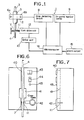
- the numeral 5 designates a dripping tube which constitutes one part of a liquid sending set or perfusion device.
- 3 is a flexible tube connected to an upper part of the dripping tube 5.
- 4 is also a flexible tube connected to the lower part thereof.
- the upper tube 3 is connected to a liquid needle or cannula to be pierced into a mouth part of a medical liquid container, and the lower tube 4 is connected with an injection needle to be pierced into a patient at a blood vessel.
- the dripping tube 5 and the tubes 3, 4 are made of transparent or half transparent vinyl chloride.
- the present invention is a device which controls the dripping rate of the medical liquid flowing in the liquid sending set, an entire body of which is shown with the numeral 1.
- the numeral 2 designates a liquid dripping sensor to be detachably attached to the dripping tube 5 where a light emitting diode 6a and a light receiving or photo diode 6b are installed.
- a liquid dripping sensor to be detachably attached to the dripping tube 5 where a light emitting diode 6a and a light receiving or photo diode 6b are installed.
- the dripping liquid interrupts the light path between the diodes 6a, 6b and a liquid drop detecting circuit 8 then detects a change of light amount, and a signal is input into a microcomputer 14.
- the numeral 7 is a stationary clamping jaw and 11 is an opposed movable clamping jaw and the lower flexible tube 4 is held by these clamping jaws (which may also be denoted "klemmen”). If the clamping jaw 11 is moved to change the amount of throttling of the tube 4, the dripping rate of the liquid in the dripping tube 5 is adjusted.
- a cam drive unit for moving the clamping jaw 11, which comprises a drive motor, cams and gears.
- a drive unit which responds to a signal from a microcomputer 14, and sends the signal to the drive motor of the clamping jaw 11, and controls the rotation speed and direction of the drive motor.
- Fig. 2 is a flow chart of the liquid dripping control system using the microcomputer 14.
- the motor of the cam drive unit 12 is reversed by the signal from the control start 16 of the device 1, and the clamping jaw 11 moves and presses the flexible tube 4 to the stationary clamping jaw 7, and the tube 4 is perfectly closed (in the following called "control starting point").
- the motor is rotated forward at high speed 17, and the clamping jaw 11 moves at the high speed 17 the flexible tube 4 in the opening direction, and a first drop in the dropping tube 5 is produced rapidly.
- the drop detecting circuit 8 detects the first drop as a dripping signal 18, and the motor is reduced 19 to the middle speed so that the movable clamping jaw 11 is reduced in movement.
- the motor When the dripping signal 22 of a n-th drop is detected, the motor is rotated at the low speed (shown by "21"), and while the clamping jaw 11 is moved at the low speed in the opening or throttling direction of the flexible tube 11, it is moved by a feedback control 23 to a predetermined value.
- Fig. 3 shows a block diagram of the feedback control 23.
- a dripping signal 25 of the drop 24 of the n drop is input into a differentiation circuit 26, and after a dripping time data 27 is calculated, the signal 25 is fed into a comparison calculating circuit 29.
- This circuit 29 has been supplied with data 28 for a drop set value and after a comparison is made with the dripping time data 27, an output signal therefrom is input into the motor drive circuit 32 via the differentiation circuit 30 and an amplifier circuit 31.
- the input signal in the motor drive circuit 32 is inverted into an output signal for driving the motor and the rotation of the motor constituting the cam drive unit 12 is controlled.
- the calmping jaw 11 is moved via the mechanisms such as cams and gears, and an object 33 (the amount of throttling the tube) to be controlled is adjusted, so that a dripping interval of n+1 drop is controlled.
- the drop of this n+1 drop is a new dropping signal 25, and subsequently the dripping speed is controlled.
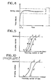
- Fig. 4 is a graph showing changes of the dripping as time passes when the dripping of the liquid is controlled by the present device. This graph will be obvious in comparison with the flow chart of Fig. 2.
- the throttling amount is the maximum at the control starting point, and the dripping number is zero.
- T is time until the drop starting point from rapid induction of the dripping of the 1st drop in correspondence to 17 to 21 of Fig. 2.
- the difference between the predetermined dripping rate and the actual dripping rate is controlled to be substantially zero, and the dripping rate is controlled not to be outside of a control range n ⁇ .
- n shows a control limiting scope by the present device.
- the movable clamping jaw 11 is returned to a cancelling point of the control start, that is, 0 point at the maximum throttling, and stops the dropping.
- Fig. 5 is a graph showing relationship between the amount of the throttling of the tube and the dripping number or rate, where A, A ⁇ , A ⁇ show the drop starting points, and B, B ⁇ , B ⁇ are approximately around the predetermined points, and C, C ⁇ , C ⁇ show the maximum dripping number points.
- the curve III (A - B - C) relates to the present invention
- the curve I (A ⁇ - B ⁇ - C ⁇ ) and the curve II (A ⁇ - B ⁇ - C ⁇ ) relate to the conventional examples where are used the tubes of different thicknesses and different materials. It is seen that the device of the present invention may control the dripping number within the determined control range, irrespectively of the type of the liquid sending sets.
- Fig. 6 is a front view of the present control device, and Fig. 7 is a side view of the same.
- the device is formed with a central groove 40 for attaching the lower flexible tube 4 of the liquid sending set, the groove 40 being formed with an intermediate groove portion 41 of large width.
- the groove portion 41 has the same depth as the tube attaching groove 40, and its width is as large as a finger would be adapted.
- the numeral 43 is a dripping number set switch
- 44 is a switch of an electric source
- 45 is an alarm lamp
- 42 is a thumb for opening and closing the movable clamping jaw, as in the prior art.
- the thumb 42 is opened to make a clearance between the stationary clamping jaw 7 and the movable clamping jaw 11, and the tube 4 is stretched by the both hands and fitted to the groove 40, and both ends of the tube 4 are forced to the bottom of the groove 40.
- the tube 4 in the intermediate groove portion 41 is pushed by the finger, and the upper part and the lower part of the tube outside of the groove portion 41 are separately fitted into the attaching groove 40 in the length.
- the lower tube is held between the stationary clamping jaw 7 and the movable clamping jaw 11.
- the intermediate groove portion 41 may be positioned in any part nearly around the both clamping jaw 7 and 11, for example, at the lower part of them.
- the present invention is not limited to the above mentioned embodiment.
- the invention may be utilized to not only the medical liquid control but also dripping controls of the liquid to be used in the physical and chemical experimental fields.
Landscapes
- Health & Medical Sciences (AREA)
- Biomedical Technology (AREA)
- Hematology (AREA)
- Vascular Medicine (AREA)
- Engineering & Computer Science (AREA)
- Anesthesiology (AREA)
- Physics & Mathematics (AREA)
- Heart & Thoracic Surgery (AREA)
- Fluid Mechanics (AREA)
- Life Sciences & Earth Sciences (AREA)
- Animal Behavior & Ethology (AREA)
- General Health & Medical Sciences (AREA)
- Public Health (AREA)
- Veterinary Medicine (AREA)
- Infusion, Injection, And Reservoir Apparatuses (AREA)
Applications Claiming Priority (4)
| Application Number | Priority Date | Filing Date | Title |
|---|---|---|---|
| JP61299944A JPS63153073A (ja) | 1986-12-18 | 1986-12-18 | 液体の滴下制御装置 |
| JP19375986U JPS6399073U (de) | 1986-12-18 | 1986-12-18 | |
| JP299944/86 | 1986-12-18 | ||
| JP193759/86U | 1986-12-18 |
Publications (3)
| Publication Number | Publication Date |
|---|---|
| EP0272467A2 true EP0272467A2 (de) | 1988-06-29 |
| EP0272467A3 EP0272467A3 (en) | 1989-05-31 |
| EP0272467B1 EP0272467B1 (de) | 1992-01-22 |
Family
ID=26508078
Family Applications (1)
| Application Number | Title | Priority Date | Filing Date |
|---|---|---|---|
| EP19870117239 Expired - Lifetime EP0272467B1 (de) | 1986-12-18 | 1987-11-23 | Vorrichtung zur Überwachung des Tropfens einer Flüssigkeit |
Country Status (4)
| Country | Link |
|---|---|
| US (1) | US4827970A (de) |
| EP (1) | EP0272467B1 (de) |
| DE (1) | DE3776306D1 (de) |
| ES (1) | ES2029471T3 (de) |
Cited By (1)
| Publication number | Priority date | Publication date | Assignee | Title |
|---|---|---|---|---|
| EP0321996A3 (de) * | 1987-12-17 | 1989-11-15 | MR. W.M.H. KERBOSCH B.V. trading under the name of MTD HOLDING | Vorrichtung zur Kontrolle des Stroms einer Infusionsflüssigkeit in einem Infusionssystem |
Families Citing this family (9)
| Publication number | Priority date | Publication date | Assignee | Title |
|---|---|---|---|---|
| US5088990A (en) * | 1989-08-30 | 1992-02-18 | Hivale Ronald S | I.V. alert system |
| WO1991009636A1 (en) * | 1989-12-28 | 1991-07-11 | Kent Archibald G | Spring powered flow rate iv controller |
| WO1991012834A1 (en) * | 1990-02-28 | 1991-09-05 | Kent Archibald G | Automatic iv clamp |
| US5409194A (en) * | 1990-04-12 | 1995-04-25 | Crouzet Electromenager | Variable flow electrically controlled valve |
| DE4129639C1 (de) * | 1991-09-06 | 1993-02-11 | Fresenius Ag, 6380 Bad Homburg, De | |
| US6290681B1 (en) * | 1994-12-20 | 2001-09-18 | Remote Medical Corporation | Flow monitoring device for medical application |
| CA2822175C (en) * | 2004-05-28 | 2016-10-18 | Enginivity Llc | Flow control and gas detection and gas removal in an intravenous fluid delivery system |
| CN102974001B (zh) * | 2012-11-13 | 2014-07-16 | 东莞市旺辉电子有限公司 | 吊针检测系统 |
| US9904296B2 (en) * | 2014-04-01 | 2018-02-27 | Honeywell International Inc. | Controlling flow in a fluid distribution system |
Family Cites Families (5)
| Publication number | Priority date | Publication date | Assignee | Title |
|---|---|---|---|---|
| US3450153A (en) * | 1967-06-26 | 1969-06-17 | Gen Electric | Electrical pulse generator and regulator for fluid flow and like control systems |
| US3601124A (en) * | 1968-08-29 | 1971-08-24 | Frank L Petree | Fluid flow regulator |
| FR2331088A1 (fr) * | 1975-11-05 | 1977-06-03 | Clin Midy | Regulateur de debit notamment pour perfusion |
| DE2917270A1 (de) * | 1979-04-27 | 1980-10-30 | Speidel & Keller Kg | Steuergeraet fuer infusionssysteme |
| JPS5836562A (ja) * | 1981-08-28 | 1983-03-03 | テルモ株式会社 | 点滴量制御装置 |
-
1987
- 1987-10-13 US US07/108,477 patent/US4827970A/en not_active Expired - Fee Related
- 1987-11-23 ES ES87117239T patent/ES2029471T3/es not_active Expired - Lifetime
- 1987-11-23 DE DE8787117239T patent/DE3776306D1/de not_active Expired - Lifetime
- 1987-11-23 EP EP19870117239 patent/EP0272467B1/de not_active Expired - Lifetime
Cited By (1)
| Publication number | Priority date | Publication date | Assignee | Title |
|---|---|---|---|---|
| EP0321996A3 (de) * | 1987-12-17 | 1989-11-15 | MR. W.M.H. KERBOSCH B.V. trading under the name of MTD HOLDING | Vorrichtung zur Kontrolle des Stroms einer Infusionsflüssigkeit in einem Infusionssystem |
Also Published As
| Publication number | Publication date |
|---|---|
| US4827970A (en) | 1989-05-09 |
| EP0272467A3 (en) | 1989-05-31 |
| DE3776306D1 (de) | 1992-03-05 |
| ES2029471T3 (es) | 1992-08-16 |
| EP0272467B1 (de) | 1992-01-22 |
Similar Documents
| Publication | Publication Date | Title |
|---|---|---|
| EP0272467A2 (de) | Vorrichtung zur Überwachung des Tropfens einer Flüssigkeit | |
| US3994294A (en) | Syringe pump valving and motor direction control system | |
| US4952205A (en) | Pressure infusion device | |
| US4018362A (en) | Automatic control for liquid flow | |
| KR100361727B1 (ko) | 모터가 있는 주입기용 제어기 및 그 제어 방법 | |
| CA1200870A (en) | Intermittent drop detecting method and apparatus | |
| JP6691551B2 (ja) | 注入装置圧力プライミングを有する治療システム | |
| US4111198A (en) | Automated intravenous fluid regulating and administering apparatus | |
| EP0164904A2 (de) | Verfahren zur Ermittlung eines Infusionsprofils und Infusionsvorrichtung | |
| KR100403695B1 (ko) | 자동제어식 포터블 점적장치 | |
| JPS63286165A (ja) | 医学注入装置 | |
| KR20160149927A (ko) | 수액 투여 속도의 자동조절장치 | |
| JPS6244949B2 (de) | ||
| US4338932A (en) | Method and apparatus for fluid flow control | |
| JPH0759851A (ja) | 輸液ポンプ | |
| WO1981000519A1 (en) | Fluid flow controller | |
| JP3198289B2 (ja) | 注入薬液制御装置 | |
| CN213911757U (zh) | 一种人工智能注射泵 | |
| CN208756697U (zh) | 自动更换吊瓶的输液装置 | |
| JPH07236692A (ja) | 輸液ポンプ | |
| CN219185265U (zh) | 一种固定位带提醒、截流、加热功能的共享输液宝 | |
| JP3378054B2 (ja) | 蠕動型輸液ポンプの駆動制御方法 | |
| JP3316002B2 (ja) | 輸液量監視装置 | |
| CN211068470U (zh) | Iabp术后抗凝药液输液管专用输药执行装置 | |
| JP7815724B2 (ja) | クランプ装置及び点滴監視装置 |
Legal Events
| Date | Code | Title | Description |
|---|---|---|---|
| PUAI | Public reference made under article 153(3) epc to a published international application that has entered the european phase |
Free format text: ORIGINAL CODE: 0009012 |
|
| AK | Designated contracting states |
Kind code of ref document: A2 Designated state(s): BE DE ES FR LU NL |
|
| PUAL | Search report despatched |
Free format text: ORIGINAL CODE: 0009013 |
|
| AK | Designated contracting states |
Kind code of ref document: A3 Designated state(s): BE DE ES FR LU NL |
|
| 17P | Request for examination filed |
Effective date: 19890606 |
|
| 17Q | First examination report despatched |
Effective date: 19901019 |
|
| GRAA | (expected) grant |
Free format text: ORIGINAL CODE: 0009210 |
|
| AK | Designated contracting states |
Kind code of ref document: B1 Designated state(s): BE DE ES FR LU NL |
|
| REF | Corresponds to: |
Ref document number: 3776306 Country of ref document: DE Date of ref document: 19920305 |
|
| ET | Fr: translation filed | ||
| REG | Reference to a national code |
Ref country code: ES Ref legal event code: FG2A Ref document number: 2029471 Country of ref document: ES Kind code of ref document: T3 |
|
| PG25 | Lapsed in a contracting state [announced via postgrant information from national office to epo] |
Ref country code: ES Free format text: LAPSE BECAUSE OF NON-PAYMENT OF DUE FEES Effective date: 19921124 |
|
| PLBE | No opposition filed within time limit |
Free format text: ORIGINAL CODE: 0009261 |
|
| STAA | Information on the status of an ep patent application or granted ep patent |
Free format text: STATUS: NO OPPOSITION FILED WITHIN TIME LIMIT |
|
| PG25 | Lapsed in a contracting state [announced via postgrant information from national office to epo] |
Ref country code: LU Free format text: LAPSE BECAUSE OF NON-PAYMENT OF DUE FEES Effective date: 19921130 Ref country code: BE Effective date: 19921130 |
|
| 26N | No opposition filed | ||
| BERE | Be: lapsed |
Owner name: KAWASUMI LABORATORIES INC. Effective date: 19921130 |
|
| PG25 | Lapsed in a contracting state [announced via postgrant information from national office to epo] |
Ref country code: NL Effective date: 19930601 |
|
| NLV4 | Nl: lapsed or anulled due to non-payment of the annual fee | ||
| PG25 | Lapsed in a contracting state [announced via postgrant information from national office to epo] |
Ref country code: FR Effective date: 19930730 |
|
| REG | Reference to a national code |
Ref country code: FR Ref legal event code: ST |
|
| PGFP | Annual fee paid to national office [announced via postgrant information from national office to epo] |
Ref country code: DE Payment date: 19981130 Year of fee payment: 12 |
|
| PG25 | Lapsed in a contracting state [announced via postgrant information from national office to epo] |
Ref country code: DE Free format text: LAPSE BECAUSE OF NON-PAYMENT OF DUE FEES Effective date: 20000901 |
|
| REG | Reference to a national code |
Ref country code: ES Ref legal event code: FD2A Effective date: 19931214 |