EP0272302B1 - Mehrzweckskleidungsstück - Google Patents
Mehrzweckskleidungsstück Download PDFInfo
- Publication number
- EP0272302B1 EP0272302B1 EP87904341A EP87904341A EP0272302B1 EP 0272302 B1 EP0272302 B1 EP 0272302B1 EP 87904341 A EP87904341 A EP 87904341A EP 87904341 A EP87904341 A EP 87904341A EP 0272302 B1 EP0272302 B1 EP 0272302B1
- Authority
- EP
- European Patent Office
- Prior art keywords
- garment
- central portion
- sleeve
- edges
- sections
- Prior art date
- Legal status (The legal status is an assumption and is not a legal conclusion. Google has not performed a legal analysis and makes no representation as to the accuracy of the status listed.)
- Expired - Lifetime
Links
- QNRATNLHPGXHMA-XZHTYLCXSA-N (r)-(6-ethoxyquinolin-4-yl)-[(2s,4s,5r)-5-ethyl-1-azabicyclo[2.2.2]octan-2-yl]methanol;hydrochloride Chemical compound Cl.C([C@H]([C@H](C1)CC)C2)CN1[C@@H]2[C@H](O)C1=CC=NC2=CC=C(OCC)C=C21 QNRATNLHPGXHMA-XZHTYLCXSA-N 0.000 claims abstract description 12
- 238000009423 ventilation Methods 0.000 claims abstract description 4
- 230000001815 facial effect Effects 0.000 claims 1
- 239000000463 material Substances 0.000 description 14
- 239000004677 Nylon Substances 0.000 description 6
- 238000000034 method Methods 0.000 description 6
- 229920001778 nylon Polymers 0.000 description 6
- 230000013011 mating Effects 0.000 description 4
- JEIPFZHSYJVQDO-UHFFFAOYSA-N iron(III) oxide Inorganic materials O=[Fe]O[Fe]=O JEIPFZHSYJVQDO-UHFFFAOYSA-N 0.000 description 2
- 230000004048 modification Effects 0.000 description 2
- 238000012986 modification Methods 0.000 description 2
- 238000007789 sealing Methods 0.000 description 2
- 238000009958 sewing Methods 0.000 description 2
- 239000012815 thermoplastic material Substances 0.000 description 2
- XLYOFNOQVPJJNP-UHFFFAOYSA-N water Substances O XLYOFNOQVPJJNP-UHFFFAOYSA-N 0.000 description 2
- 241000239226 Scorpiones Species 0.000 description 1
- 241000270295 Serpentes Species 0.000 description 1
- 230000004308 accommodation Effects 0.000 description 1
- 230000000694 effects Effects 0.000 description 1
- 239000004744 fabric Substances 0.000 description 1
- 239000011152 fibreglass Substances 0.000 description 1
- 239000004033 plastic Substances 0.000 description 1
- 230000001681 protective effect Effects 0.000 description 1
- 238000004826 seaming Methods 0.000 description 1
- 239000000725 suspension Substances 0.000 description 1
- 229920002994 synthetic fiber Polymers 0.000 description 1
- 239000004758 synthetic textile Substances 0.000 description 1
Images



Classifications
-
- A—HUMAN NECESSITIES
- A41—WEARING APPAREL
- A41D—OUTERWEAR; PROTECTIVE GARMENTS; ACCESSORIES
- A41D15/00—Convertible garments
- A41D15/04—Garments convertible into other articles
-
- E—FIXED CONSTRUCTIONS
- E04—BUILDING
- E04H—BUILDINGS OR LIKE STRUCTURES FOR PARTICULAR PURPOSES; SWIMMING OR SPLASH BATHS OR POOLS; MASTS; FENCING; TENTS OR CANOPIES, IN GENERAL
- E04H15/00—Tents or canopies, in general
- E04H15/32—Parts, components, construction details, accessories, interior equipment, specially adapted for tents, e.g. guy-line equipment, skirts, thresholds
- E04H15/34—Supporting means, e.g. frames
- E04H15/36—Supporting means, e.g. frames arch-shaped type
- E04H15/40—Supporting means, e.g. frames arch-shaped type flexible
Definitions
- the present invention is in the field of a garment which can be used by outdoors persons as well as military personnel. More particularly it is a garment which provides protection against weather as a short coat, long coat or tent.
- the sleeping accommodation modes required the presence of suitable vertical structure such as trees for the suspension of the end portions of the article.
- the multipurpose article of USP 4.484.362 was basically a rectangular sheet. Extensive experimental field trials disclosed that there was excessive material in both end portions which served no true purpose in the sleeping shelter and hammock uses. Furthermore, the ratio of width to length was restriction in the sleeping shelter mode as to provide a cocoon like environment which was uncomfortable to user. Also the width of the multipurpose garment of USP 4.484.362 was found to be somewhat restrictive in walking as well as in rainy weather directing the flow of water onto the legs and feet of the wearer.
- the top and bottom portions of the garment have been taper reduced, the garment has been enlarged in width and length, sleeves have been provided to give the garment in the sleeping shelter mode an independently suspended form which has a water-tight integrity of approximately 23cm (3 inches) above the surface upon which the sleeping mode has been erected.
- the present invention uses a material from the many available which has the characteristics ranging from water-impermeable/air-permeable to water and air impermeable. Within this range, there are many fabrics.
- An additional characteristic of a desirable material is that the material does not become rigid or stiff at sub-zero temperatures. This is particularly important in military application since a stiff material is creates unwanted noise as the wearer moves through underbrush and the like.
- the material will be moisture impermeable and soft. Polyeurathane coated synthetic fabrics are preferable.
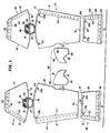
- FIG 1 shows the major components of the present invention before assembly. This exploded view was selected to display the shapes of the components of the invention which results in a multipurpose garment which has less unneeded and unused material and more correctly provides the variety of applications to the need of the user than the previously cited patent and application of the assignee.
- the present invention comprises a left body portion 60, a right body portion 70, lower left back body portion 10, a lower right back body portion 40, a lower left front body portion 90, a lower right front body portion 100 and a hood portion 80.
- the body portions 60 and 70 are generalized rhombic in shape, having lower front edges 64 and 74 from which extend outwardly extending edges 61, 62, 71 and 72.
- the terminus of edges 61, 62, 71, and 72 which are opposite edges 64 and 74 are edges 63 and 73 which are arcurate in contrast to straight edges 64 and 74.
- the arcurate edges 63 and 73 drape the present invention more closely over a backpack when the invention is used as a coat and provide a more compatible curvature of the garment when used as a tent.
- Tent pole sleeves 66 and 76 are provided to receive the tent poles provided with the present invention.
- Body portion 60 and 70 are provided with matching cut out edges 65 and 75 which when edges 62 and 72 are sewn together provide an opening into which the hood portion 80 is inserted after edges 81, 82, 83, 84 are sewn together and edges 85 and 86 are sewn to edges 65 and 75 to provide a head opening circumscribed by edges 87 and 88 which carry a sleeve 89.
- Lower back portions 10 and 40 are rhombic in shape, edges 13 and 43 have an arcurate form having the same but opposing radius of curvature as edges 63 and 73 of body portions 60 and 70 to which they are joined by sewing and sealing.
- Portions 10 and 40 are provided with rhombic openings 18 and 48 adjacent edges 13 and 43 which provide ventilation when the present invention is in the tent mode. Openings 18 and 48 are covered by fiberglass mesh material 19 and 49. The mesh material 19 and 49 is held in place by rhombic frames 20 and 50 of the basic material which are sewn in place and sealed. Nylon loop strips 21 and 51 are sewn and sealed to encompass openings 18 and 48.
- Flaps 22 and 52 to close openings 18 and 48 respectively have circumferentually mounted nylon locking material 23 and 53 and are joined to portions 10 and 40 when edges 13 and 43, 63 and 73 and pole sleeves 66 and 76 are sewn together and sealed.
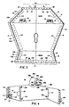
- End portions of edges 11 and 41 carry sleeves 15 and 45 as seen in FIG 3 each of which contains an elastomeric 121 cord in FIG 14, each end of each cord having an end tip 122 having a V-shaped slot 123 to catch and hold the a portion of the cord when the cord is used in the application of the invention.
- the sleeves 15 and 45 are formed by sealingly sewing a separate sleeve portion to the underside of respective back portions 10 and 40 along edges 11 and 41 and seaming them along interior spaced seams 16 and 46 and sealing these seams as seen in FIGS. 1 and 3.
- Lower front portions 90 and 100 are rhombic in shape with parallel edges 93 and 94 and 103 and 104.
- Sleeves 95/105 seen in FIG 3 are formed in the same manner as sleeves 15/45 with sealed interior seams 96 and 106, the joined sleeve containing an elastomeric cord 121 with end tip 122 as in FIG 14.
- Portions 90 and 100 carry tent pole sleeves 97 and 107 which are held within the seam joining edges 93 and 103 which in turn are sealed. It is to be noted that edges 91, 92, 101 and 102 taper outwardly to edges 94 and 104.
- This outward taper results in edges 94 and 104 extending forwardly and outwardly of the body of the wearer when the present garment is worn in the great coat configuration in FIG 11, particularly during rain thus directing the rain away from the lower legs and shoes of the wearer.
- the outward taper also provides increased stability when the present invention is used as a tent.
- edges 13, 63, 43 and 73 when sewn together and sealed do not permit clear planular view of the assembled portions of the present invention in as much as the arcurate edges when sewn together create a bunching up of the garment along those seams which cannot be clearly and understandably illustrated by drawings. Therefore it was decided to present the assembled portions of the garment as shown in these figures for simplicity and clarity in viewing the assembled garment.
- end portions 11/41 and 94/104 carry a plurality of snaps 110 and 111 respectively.
- Edge portions 12, 61, 91, 102, 71 and 44 similarly carry a line of snaps 113 and 114 respectively.
- snaps 113 and 114 are spaced interiorly from their respective edges.
- a continuous line of double acting zippers 112 is sealingly sewn along edges 12, 61, and 91 and spacedly and sealingly sewn adjacent to edges 44, 71 and 104 on the interior side of the present garment.
- the positioning of zipper 112 spaced from edges 44, 71 and 104 provides an over hanging flap 112a to protect the joined zippers in a tent mode from rain.
- the tent poles seen disassembled in FIG 15 are inserted into the pole sleeves 66, 76, 77 and 107 as will be subsequently described.
- the ends of the assembled tent poles are inserted in a plurality of respective tent pole pockets 115 which are attached to portions 60, 70, 90 and 100 adjacent the respective ends of the respective tent pole sleeves 66, 76, 97 and 107.
- the tent pole pockets 115 comprises at least one layer of a web strap 116 secured at one end to its respective garment body portion by sealed stitching 117 as shown in FIG 13. The other end of the strap 116 is folded over as shown and stitched at 118 to form a pocket 119 to receive the end of an assembled tent pole as will be described.
- hood 80 is provided with a tab 88a attached to the rear upper surface of the hood and having a nylon loop patch 88b which can be engaged with a nylon hook patch 88c on the visor 88d of the hood to hold the hood in an open position.
- hood sleeve 89 is provided with a tab 88e having a nylon loop patch 88f which can engage a nylon loop patch 88g to close hood about the face of the wearer to cover the nose and mouth of the wearer.
- hood means 80 is sewn and sealed along edges 81, 82, 83 and 84 and edges 85 and 86 are sewn and sealed into edges 65 and 75.
- Edges 88 and 87 are folded over to form a sleeve 89 (FIGS 2 and 4) through which runs a hood cord 89a to selectively draw the hood around the head of the wearer or to close the hood opening completely in the tent configurations of FIGS 5, 6 and 16.
- a slide 89b is provided to engage each end portion of cord 89a to restrain the hood opening in the desired position.
- sleeves 15/45 and sleeves 95/105 terminate in an angled edged matching edges 12, 44, 91 and 102.
- Sleeves 15/45 and 95/105 are open at each end which provides access to the elastomeric cord 121 which extends through each sleeve and terminates in a flat plastic cord holder 122, each holder having a notch 123 therein which receives and holds portions of the respective cord when it is elongated.
- the device disclosed in USP 3.953.911 is preferred.
- each sleeve is also provided with a grommet 24 and 109 adjacent seam 14/42 and seam 92/101 respectively.
- FIGS 7 and 9 show the bug-proof netting 130 which is used in the fair weather shelter seen in those figures.
- the-netting is rhombic in shape and carries a doubleacting zipper 131 around its periphery. Zipper 131 mates with zipper 112 shown in FIG 3.
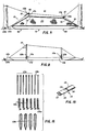
- FIG 15 shows the accessories used to form the inclement weather shelters seen in FIGS 5, 6, and 16. They comprises to pole sections having threaded male portions on one end with mating female portions on the opposite end and 2 pole sections having only mating female portions on one end; 6 tent greylines of flexible woven, weather resistant thermoplastic material; and 4 tents stakes as shown, preferably of rust resistant material and capable of being pounded into the ground.
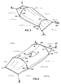
- the single occupant shelter seen in FIG 5 is formed as follows. Lay out the garment with the inner side (FIG 3) up. Fold edges 41, 71 and 104 over to edges 12, 61 and 91 and close the respective zippers. Snap edges 11/41 to edges 94/104 together. Pull ends of hood cords 89 to completely close hood about opening 65/75 and securely tie the hood. Makeup two tent poles each of 4 sections 125a and one section 125b. Beginning on the zippered side insert one pole through sleeve 97 and insert the extending pole end into adjacent pole pocket 115. Then arching the pole insert the opposite pole end into the adjacent pole pocket 115. Then arching the pole insert the opposite pole end into the adjacent pole pocket 115. Repeat these steps with the other pole.
- FIGS 7 and 9 show the bug-proof netting 130 which is used in the fair weather shelter seen in those figures.
- the netting is rhombic in shape and carries a double acting zipper 131 around its periphery.
- FIG 15 shows the accessories used to form the inclement weather shelters seen in FIGS 5, 6 and 16. They comprise 6 pole sections having threaded male portions on one end with mating female portions on the opposite end and 2 pole sections having only mating female portions on one end; 6 tent guy lines of flexible, woven, weather resistant thermoplastic material; and 4 tent stakes as shown, preferably of rust resistant material and capable of being pounded into the ground.
- the single occupancy shelter seen in FIG 5 is formed as follows. Lay out the garment with the inner side (FIG 3) up. Fold edges 41, 71 and 164 over to edges 12, 61 and 91 and close the respective zippers. Snap edges 11/41 to edges 94/104 together. Pull end of hood cord 89 to completely close hood about opening 65/95 and securely tie the hood. Make up two tent poles each of 4 sections 125a and 125b. Beginning on the zippered side insert one pole through sleeve 97 and insert the extending pole end into adjacent pole pocket 115. Then arching the pole insert the opposite pole end into the adjacent pole pocket 115. Repeat these steps with the other pole. Insert the end of one line 125 in grommet 24 and secure the end of the line.
- the two man shelter of FIG 6 is formed by firstly closing off both hood openings as described for FIG 5.
- One garment is placed on the ground with the outer or hood side down.
- the other garment is placed over the first with the hood side up.
- the zippers of both garments and the end snaps are joined together.
- Two tent poles are assembled from the ferrule sections 125a and one unferruled section 125b.
- One pole is inserted into sleeve 97/107. After passing through the sleeves one end of the pole is inserted into adjacent pole pocket 115 and the other end is then inserted into pole pocket 115 thus arching the pole.
- the same procedure is followed with the other tent pole and the garment is extended to its fullest length.
- One guy line 125c with its attached cabiclic 125e is inserted into grommet 22, another into grommet 53 and yet another into grommet 24. At the other end, a guy line 125c with associated cabiclic is inserted into grommet 97, another into grommet 108 and a third into grommet 109.
- the guy line attached to grommets 22, 53, 97 and 108 are then drawn out at angles of about 30 degrees from the respective ends of the so assembled garments and secured to stakes 125a.
- Guy lines attached to grommets 24 and 109 are drawn out perpendicular to the ends of the assembled garments and secured to takes 125d.
- the fair weather shelter of FIG 7 is formed by again closing off the hood as described with reference to FIG 5.
- Netting 130 is provided around its periphery with a double acting zipper 131 which is compatible with zipper 112. End portions 10 and 40 are snapped together with snaps 110 and 111.
- Two poles are formed with 3 ferruled sections 125a and one unferruled section 125b. One pole is inserted into the end of pole sleeve 107 nearest the zippered netting and garment juncture. The end of the pole exiting sleeve 107 is inserted into pole pocket 115. The other end of the pole is inserted into pole pocket 115. The same procedure is followed with reference to sleeve 76.
- One guy line 125c with its cabiclic 125e is inserted into grommet 22 and drawn out to be secured to a stake 125d.
- Another guy line 125c with its associated cabiclic 125e is inserted into grommet 97 and is attached to a vertical support as available.
- Additional guylines 125c are similarly secured to grommets 22 and 108 and secured as described with reference to grommets 53 and 108.
- Additional guy lines 125c with associated cabiclics 125e are inserted into grommets 24 and 109 and attached to a stake 125 and to a vertical support.
- the sitting shelter shown in FIG 10 is formed by zipping sides 41, 71, 104, 12, 61 and 91 together approximately half way. Holding the thus zippered edges in front, step into the garment, lift up the unzippered portions up to insert the head into the hood opening. Throw the remaining portion of the garment over the head to the back, snap edges 11, 41, 94 and 104 together, turn the garment so the zippered portions are in the back and raise the hood over the head, leaving the unzippered together portions free.
- Cord 121 is drawn from one end of sleeve 15/41 and passed around the back of the wearer to approximately waist level. The other end of cord 121 is held and the cord 121 is elongated to encompass the waist and one end is inserted in groove 123 thus forming a belt.
- the garment is smoothed over the front by pressing the excess material around each side of the wearer to the rear to provide the excess needed to cover any pack worn on the back of the wearer.
- the front edges 94 and 104 of the long coat are raised to approximately waist level.
- Cord 121 is then pulled from both ends of sleeve 95/105 and brought around the waist and inserted into one of the grooves 123 as was done in forming the long coat.
- the one man shelter seen in FIG 16 is formed as described with reference to FIG 5 and FIG 8 with the exception that ends 11/41 and ends 94/104 are not guyed out to stakes 125d. Instead ends 11/41 and 94/104 are each gathered together as shown and cord 121 in the respective sleeves is used to secure the gathered ends as shown.
- the guy lines are attached to respective pole pockets 115 in lieu of the aforedescribed grommets. The guy lines are secured to stakes 125d as shown.
- the purpose of this modification of FIG 5 is for use in desert areas to prevent entry of snakes, scorpions and the like through otherwise snapped together edges 11/41 and 94/104 because of the cool or cold night temperatures.
- An additional guy line 125c is secured to each gathered end and secured to a stake 125d to elongate the end portions as much as possible.
- a bag is provided to carry the tent accessories.
- a pocket shown in phantom 160 in FIG 2 may be provided.
Landscapes
- Engineering & Computer Science (AREA)
- Textile Engineering (AREA)
- Architecture (AREA)
- Civil Engineering (AREA)
- Structural Engineering (AREA)
- Outer Garments And Coats (AREA)
- Tents Or Canopies (AREA)
Claims (10)
Priority Applications (1)
| Application Number | Priority Date | Filing Date | Title |
|---|---|---|---|
| AT87904341T ATE62792T1 (de) | 1986-06-23 | 1987-06-22 | Mehrzweckskleidungsstueck. |
Applications Claiming Priority (2)
| Application Number | Priority Date | Filing Date | Title |
|---|---|---|---|
| US06/877,345 US4703521A (en) | 1986-06-23 | 1986-06-23 | Multi-purpose garment |
| US877345 | 1986-06-23 |
Publications (3)
| Publication Number | Publication Date |
|---|---|
| EP0272302A1 EP0272302A1 (de) | 1988-06-29 |
| EP0272302A4 EP0272302A4 (de) | 1988-10-20 |
| EP0272302B1 true EP0272302B1 (de) | 1991-04-24 |
Family
ID=25369794
Family Applications (1)
| Application Number | Title | Priority Date | Filing Date |
|---|---|---|---|
| EP87904341A Expired - Lifetime EP0272302B1 (de) | 1986-06-23 | 1987-06-22 | Mehrzweckskleidungsstück |
Country Status (6)
| Country | Link |
|---|---|
| US (1) | US4703521A (de) |
| EP (1) | EP0272302B1 (de) |
| JP (1) | JPH01500764A (de) |
| KR (1) | KR910000930B1 (de) |
| AU (1) | AU592210B2 (de) |
| WO (1) | WO1987007820A1 (de) |
Families Citing this family (37)
| Publication number | Priority date | Publication date | Assignee | Title |
|---|---|---|---|---|
| US4998296A (en) * | 1989-11-28 | 1991-03-12 | Stames Rebecca M | Hypothermia protection suit collapsible into compact package for storage |
| US4989282A (en) * | 1990-05-17 | 1991-02-05 | Mark Goldstein | Extendable sleeping bag |
| US5226193A (en) * | 1990-06-05 | 1993-07-13 | Chen Yen Chu | Child's sleeping garment |
| IT226678Z2 (it) * | 1992-06-09 | 1997-07-01 | Aragosta | Telo facilmente trasformabile in veste per esempio in accappatoio |
| US5664257A (en) * | 1996-09-17 | 1997-09-09 | Hall; Richard | Convertible bag/hat/halter top |
| WO1998030127A1 (en) * | 1997-01-10 | 1998-07-16 | Mark Bahlig | Tent transformable into a jacket |
| AU721092B2 (en) * | 1997-05-09 | 2000-06-22 | Hilliam, David Norman | An improved sleeping bag |
| US5924132A (en) * | 1997-11-10 | 1999-07-20 | Wigutow; Jerald N. | Portable shelter/garment |
| US6185743B1 (en) | 1999-06-10 | 2001-02-13 | John D. Mick | Beach toga with partial belt |
| US6351851B1 (en) | 2001-01-31 | 2002-03-05 | Stephen J. Yardan | Personal shelter device |
| US6341379B1 (en) | 2001-03-20 | 2002-01-29 | Martin Kokus | Combination tent-rain cape |
| JP2002309410A (ja) * | 2001-04-17 | 2002-10-23 | Takehiko Sanada | 多機能コート |
| GB0308684D0 (en) * | 2003-04-15 | 2003-05-21 | Teal Safety Ltd | A multi-purpose apparatus |
| ATE378686T1 (de) * | 2003-06-30 | 2007-11-15 | Koninkl Philips Electronics Nv | Eine proportionale eingabenschnittstelle |
| US7849534B2 (en) * | 2003-08-13 | 2010-12-14 | American Recreation Products, Inc. | Sleeping bag with vented footbox |
| US20060174391A1 (en) * | 2005-02-10 | 2006-08-10 | Shannon L K | Cold weather outerwear |
| US20070050882A1 (en) * | 2005-04-28 | 2007-03-08 | David Eisenhuth | Convertible outerwear garment with thermal insulation |
| US20070061940A1 (en) * | 2005-08-25 | 2007-03-22 | Cazares Darryl L | Hooded changing garment |
| US20070145089A1 (en) * | 2005-12-27 | 2007-06-28 | Blacks Creek Guide Gear Inc. | Backpack device configured for carrying oversized cargo comfortably |
| FR2911049A1 (fr) * | 2007-01-09 | 2008-07-11 | Alice Cayrel | Vetement exterieur transformable en tente |
| US20090031473A1 (en) * | 2007-08-02 | 2009-02-05 | Harlan Hartfield | Noiseless over garment with apertures |
| US7908676B2 (en) * | 2007-08-27 | 2011-03-22 | Linda Gutshe | Shacket™ |
| US8161991B2 (en) * | 2007-09-07 | 2012-04-24 | Wes Ryland Johnson | Multipurpose camping hammock |
| US20090249527A1 (en) * | 2008-04-02 | 2009-10-08 | Hunte Adrian C | Changing garment convertible to carrying bag |
| US20100122395A1 (en) * | 2008-11-14 | 2010-05-20 | Wanda Wall | Convertible multifunction covering |
| US7832032B2 (en) * | 2009-04-03 | 2010-11-16 | Haislip Richard E | Multipurpose sleeping bag |
| US9615610B2 (en) * | 2013-06-14 | 2017-04-11 | Hope Biller | Outdoor convertible garment |
| US9903135B1 (en) | 2014-10-09 | 2018-02-27 | Mihail Angelov Todorov | Rainwear-shelter with attachable perimeters |
| US9631395B1 (en) * | 2014-10-09 | 2017-04-25 | Mihail Angelov Todorov | Multifunctional outdoor shelter system with variably attachable hooded garment floor and canopy |
| US10856587B2 (en) * | 2015-04-21 | 2020-12-08 | Mark T. Standard | Survival, evacuation, rescue, and recovery vest device |
| US10897982B2 (en) * | 2015-10-02 | 2021-01-26 | Dutch Clips LLC | Hammock |
| AT15276U3 (de) * | 2015-10-15 | 2018-03-15 | Campfire Outdoors Gmbh | Zelt |
| AT518358B1 (de) * | 2016-03-07 | 2018-11-15 | Campfire Outdoors Gmbh | Zelt |
| US10687571B2 (en) | 2017-02-27 | 2020-06-23 | Adiff, LLC | Convertible jacket |
| CN111374381B (zh) * | 2020-04-13 | 2021-11-30 | 浙江理工大学 | 一种可穿戴式帐篷 |
| US20220312869A1 (en) * | 2021-04-01 | 2022-10-06 | Guy Barbeau | Body protective cover (hugbag) |
| US11930868B2 (en) * | 2021-09-30 | 2024-03-19 | Tara A. Zlotkin | Wearable blanket usable as a blanket, towel, wrap, and worn fashionably as a skirt |
Family Cites Families (11)
| Publication number | Priority date | Publication date | Assignee | Title |
|---|---|---|---|---|
| US703245A (en) * | 1901-07-16 | 1902-06-24 | William S Faulkner | Shelter-tent half and poncho. |
| US1895911A (en) * | 1931-10-07 | 1933-01-31 | Jr George C Bosson | Combined tent and hood-garment |
| US3584315A (en) * | 1969-05-21 | 1971-06-15 | Roger J Hardy | Dual tarp apparatus |
| US4103377A (en) * | 1977-01-27 | 1978-08-01 | Mel A. Pfreizer | Knapsack-parka sleeping bag |
| US4180867A (en) * | 1978-02-27 | 1980-01-01 | Ridgeway Marcus L Jr | Space enclosing member |
| EP0031860A1 (de) * | 1979-12-20 | 1981-07-15 | Francital Société dite: | Faltbares Zelt, das als Pelerine verwendbar und auf einen Rucksack anlegbar ist |
| US4484362A (en) * | 1980-05-21 | 1984-11-27 | Asher Ron E | Multi-purpose outerwear |
| NO833318L (no) * | 1983-09-15 | 1985-03-18 | More Tekstilfab | Overlevelsesteppe |
| US4605029A (en) * | 1984-03-06 | 1986-08-12 | Russell Chesley G | Self supporting outdoor sleeping system |
| GB2163942B (en) * | 1984-09-04 | 1988-08-17 | David Eric Flowers | Multi-purpose coat |
| US4594735A (en) * | 1986-01-03 | 1986-06-17 | Gerald Rolf | Combination poncho and tent |
-
1986
- 1986-06-23 US US06/877,345 patent/US4703521A/en not_active Expired - Lifetime
-
1987
- 1987-06-22 KR KR1019880700152A patent/KR910000930B1/ko not_active Expired
- 1987-06-22 EP EP87904341A patent/EP0272302B1/de not_active Expired - Lifetime
- 1987-06-22 JP JP62503959A patent/JPH01500764A/ja active Pending
- 1987-06-22 AU AU75860/87A patent/AU592210B2/en not_active Ceased
- 1987-06-22 WO PCT/US1987/001420 patent/WO1987007820A1/en not_active Ceased
Also Published As
| Publication number | Publication date |
|---|---|
| AU7586087A (en) | 1988-01-12 |
| EP0272302A4 (de) | 1988-10-20 |
| KR910000930B1 (ko) | 1991-02-19 |
| KR880701078A (ko) | 1988-07-25 |
| EP0272302A1 (de) | 1988-06-29 |
| AU592210B2 (en) | 1990-01-04 |
| JPH01500764A (ja) | 1989-03-16 |
| US4703521A (en) | 1987-11-03 |
| WO1987007820A1 (en) | 1987-12-30 |
Similar Documents
| Publication | Publication Date | Title |
|---|---|---|
| US4703521A (en) | Multi-purpose garment | |
| US5924132A (en) | Portable shelter/garment | |
| US20180213952A1 (en) | Multi-Purpose Blanket | |
| CA2205296C (en) | Convertible panel and shelter system | |
| US4686720A (en) | Covered hammock | |
| US4484362A (en) | Multi-purpose outerwear | |
| US5452476A (en) | Anorak attached to belt pouch for easy deployment and use with a backpack | |
| US20090205096A1 (en) | Integrated And Convertible Garment And Portable Storage System | |
| US4138742A (en) | Convertible cushion | |
| US5123117A (en) | Combination backpack and reversible jacket | |
| US9072367B2 (en) | Fully enclosed four season camp hammock | |
| US7908676B2 (en) | Shacket™ | |
| US20090241235A1 (en) | Convertible Garment | |
| US20100031413A1 (en) | Convertible jacket systems | |
| US20110179548A1 (en) | Integrated shelter and multi-functional garment | |
| EP3383208B1 (de) | Doppelummantelungsanordnung | |
| US5899571A (en) | Beach towel, tote bag and beach umbrella system | |
| US7434591B2 (en) | Rain protection umbrella | |
| US11812879B2 (en) | Modular portable bedding system | |
| US6851126B1 (en) | Ghillie suit | |
| US9903135B1 (en) | Rainwear-shelter with attachable perimeters | |
| EP0026151A1 (de) | Mehrzweck-Aussenbekleidung | |
| US9631395B1 (en) | Multifunctional outdoor shelter system with variably attachable hooded garment floor and canopy | |
| US12029309B1 (en) | Multifunctional sun protection articles and methods | |
| US20060137731A1 (en) | An ultralight backpacking combination cloak and tent |
Legal Events
| Date | Code | Title | Description |
|---|---|---|---|
| PUAI | Public reference made under article 153(3) epc to a published international application that has entered the european phase |
Free format text: ORIGINAL CODE: 0009012 |
|
| AK | Designated contracting states |
Kind code of ref document: A1 Designated state(s): AT BE CH DE FR GB IT LI LU NL SE |
|
| 17P | Request for examination filed |
Effective date: 19880531 |
|
| A4 | Supplementary search report drawn up and despatched |
Effective date: 19881020 |
|
| 17Q | First examination report despatched |
Effective date: 19891009 |
|
| GRAA | (expected) grant |
Free format text: ORIGINAL CODE: 0009210 |
|
| AK | Designated contracting states |
Kind code of ref document: B1 Designated state(s): AT BE CH DE FR GB IT LI LU NL SE |
|
| PG25 | Lapsed in a contracting state [announced via postgrant information from national office to epo] |
Ref country code: IT Free format text: LAPSE BECAUSE OF FAILURE TO SUBMIT A TRANSLATION OF THE DESCRIPTION OR TO PAY THE FEE WITHIN THE PRESCRIBED TIME-LIMIT;WARNING: LAPSES OF ITALIAN PATENTS WITH EFFECTIVE DATE BEFORE 2007 MAY HAVE OCCURRED AT ANY TIME BEFORE 2007. THE CORRECT EFFECTIVE DATE MAY BE DIFFERENT FROM THE ONE RECORDED. Effective date: 19910424 Ref country code: LI Effective date: 19910424 Ref country code: CH Effective date: 19910424 Ref country code: SE Effective date: 19910424 Ref country code: NL Effective date: 19910424 Ref country code: BE Effective date: 19910424 Ref country code: AT Effective date: 19910424 |
|
| REF | Corresponds to: |
Ref document number: 62792 Country of ref document: AT Date of ref document: 19910515 Kind code of ref document: T |
|
| REF | Corresponds to: |
Ref document number: 3769614 Country of ref document: DE Date of ref document: 19910529 |
|
| PG25 | Lapsed in a contracting state [announced via postgrant information from national office to epo] |
Ref country code: LU Free format text: LAPSE BECAUSE OF NON-PAYMENT OF DUE FEES Effective date: 19910630 |
|
| PG25 | Lapsed in a contracting state [announced via postgrant information from national office to epo] |
Ref country code: GB Effective date: 19910724 |
|
| REG | Reference to a national code |
Ref country code: CH Ref legal event code: PL |
|
| NLV1 | Nl: lapsed or annulled due to failure to fulfill the requirements of art. 29p and 29m of the patents act | ||
| EN | Fr: translation not filed | ||
| PG25 | Lapsed in a contracting state [announced via postgrant information from national office to epo] |
Ref country code: FR Effective date: 19910920 |
|
| PLBE | No opposition filed within time limit |
Free format text: ORIGINAL CODE: 0009261 |
|
| STAA | Information on the status of an ep patent application or granted ep patent |
Free format text: STATUS: NO OPPOSITION FILED WITHIN TIME LIMIT |
|
| GBPC | Gb: european patent ceased through non-payment of renewal fee | ||
| 26N | No opposition filed | ||
| REG | Reference to a national code |
Ref country code: FR Ref legal event code: ST |
|
| PGFP | Annual fee paid to national office [announced via postgrant information from national office to epo] |
Ref country code: DE Payment date: 19990706 Year of fee payment: 13 |
|
| PG25 | Lapsed in a contracting state [announced via postgrant information from national office to epo] |
Ref country code: DE Free format text: LAPSE BECAUSE OF NON-PAYMENT OF DUE FEES Effective date: 20010403 |