EP0272227A2 - Membran-Bremszylinder für Kraftfahrzeuge - Google Patents
Membran-Bremszylinder für Kraftfahrzeuge Download PDFInfo
- Publication number
- EP0272227A2 EP0272227A2 EP87830441A EP87830441A EP0272227A2 EP 0272227 A2 EP0272227 A2 EP 0272227A2 EP 87830441 A EP87830441 A EP 87830441A EP 87830441 A EP87830441 A EP 87830441A EP 0272227 A2 EP0272227 A2 EP 0272227A2
- Authority
- EP
- European Patent Office
- Prior art keywords
- tubular body
- annular
- brake cylinder
- outlet chamber
- stem
- Prior art date
- Legal status (The legal status is an assumption and is not a legal conclusion. Google has not performed a legal analysis and makes no representation as to the accuracy of the status listed.)
- Granted
Links
Images
Classifications
-
- F—MECHANICAL ENGINEERING; LIGHTING; HEATING; WEAPONS; BLASTING
- F16—ENGINEERING ELEMENTS AND UNITS; GENERAL MEASURES FOR PRODUCING AND MAINTAINING EFFECTIVE FUNCTIONING OF MACHINES OR INSTALLATIONS; THERMAL INSULATION IN GENERAL
- F16D—COUPLINGS FOR TRANSMITTING ROTATION; CLUTCHES; BRAKES
- F16D65/00—Parts or details
- F16D65/14—Actuating mechanisms for brakes; Means for initiating operation at a predetermined position
- F16D65/16—Actuating mechanisms for brakes; Means for initiating operation at a predetermined position arranged in or on the brake
- F16D65/22—Actuating mechanisms for brakes; Means for initiating operation at a predetermined position arranged in or on the brake adapted for pressing members apart, e.g. for drum brakes
-
- B—PERFORMING OPERATIONS; TRANSPORTING
- B60—VEHICLES IN GENERAL
- B60T—VEHICLE BRAKE CONTROL SYSTEMS OR PARTS THEREOF; BRAKE CONTROL SYSTEMS OR PARTS THEREOF, IN GENERAL; ARRANGEMENT OF BRAKING ELEMENTS ON VEHICLES IN GENERAL; PORTABLE DEVICES FOR PREVENTING UNWANTED MOVEMENT OF VEHICLES; VEHICLE MODIFICATIONS TO FACILITATE COOLING OF BRAKES
- B60T17/00—Component parts, details, or accessories of power brake systems not covered by groups B60T8/00, B60T13/00 or B60T15/00, or presenting other characteristic features
- B60T17/08—Brake cylinders other than ultimate actuators
- B60T17/081—Single service brake actuators
Definitions
- the present invention relates to a diaphragm brake cylinder for motor vehicles, of the type generally used on engines provided with wedge brakes.
- the invention relates to a diaphragm brake cylinder comprising: - a rigid casing provided with at least one inlet opening and at least one outlet opening for an operating fluid, generally air, and including a diaphragm supported by the walls of the casing and defining an inlet chamber and an outlet chamber communicating with the inlet opening and the outlet opening respectively, - a tubular body connected to the rigid casing and communicating with the outlet chamber, - a stem-like transmission and control member cooperating with the diaphragm and slidably mounted in the tubular body, and - guide means interposed between the stem of the transmission member and the tubular body, for allowing relative movement between the transmission member and the tubular body.
- the brake cylinder which is the subject of the present invention is characterised in that the guide means consist of a channel-like annular member mounted in the tubular body with its concavity facing the outlet chamber and having in its dorsal region at least one opening for allowing the operating fluid to flow between the outlet chamber and the cavity of the tubular body, and in that it includes an annular filter element housed in the concavity of the annular guide member and intended to filter the operating fluid flowing between the outlet chamber and the tubular body during operation.
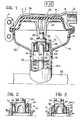
- a brake cylinder comprises a rigid casing 2 of sheet steel formed by two half-shells 2a and 2b clamped together by a stirrup 4.
- a diaphragm 6 is interposed between the two half-shells and defines within the casing an inlet chamber 8 provided with at least one opening 12 for the supply of pressurised air and an outlet chamber 10 with at least one opening 14 for discharge of the air.
- a tubular drum 16 defining a cavity 18 is connected to the casing 2.
- the drum 16 has an externally-threaded end portion 16a for connection to a cylindrical body, schematically indicated 20 in the drawings, in which wedges, not illustrated, are housed.
- a transmission and control member 22 formed by a plate 24 which cooperates with the diaphragm 6 and by a stem 26 which defines a seat 28 intended to receive a push rod 30.
- the plate 24 is kept in contact with the diaphragm 6 by means of a helical spring 32 reacting between the rod 30 and the body 20.
- the stem 26 of the transmission member 22 is mounted inside the drum 16 with the interposition of an annular channel-like guide member 34 of elastomeric material.
- the annular guide member 34 has a radially internal wall 36 and a radially external wall 38 connected by an annular base 40 so as to define an annular channel 42.
- a plurality of angularly-spaced radial partitions 44 which subdivide the channel 42 into a plurality of compartments 46 extend between the walls 36 and 38.
- the base wall 40 has at least one opening 50 which puts the outlet chamber 10 into flow communication with the cavity 18.
- the internal wall 36 of the guide member 34 has an inwardly-projecting annular rib 52 which is resiliently engageable with a groove 54 formed in the stem 26.
- the guide member 34 is mounted fast with the stem 26 with the concavity of the channel facing towards the chamber 10 and with the external surface of the wall 38 sealingly slidably engaged with the internal surface of the drum 16.
- the annular filter element 48 is housed in the channel 42 so as to intercept dust and impurities in the airstream which flows between the outlet chamber 10 and the cavity 18 through the openings 50 during operation of the brake cylinder.
- the use of a filter element thus allows the infiltration of impurities, whose progressive accumulation could even lead to jamming of the movable parts of the braking element, to be prevented so that the reliability of the device is improved.
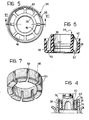
- the filter element 48 has an annular portion 58 from which extends a plurality of angularly spaced protruberances 60, each engageable with a respective compartment 46.
- the filter element 48 may consist of porous synthetic or metallic material, for example, sintered powder.
- the filter element 48 is preferably kept in its seat by the use of an annular metal stop member 62.
- the stop member 62 is cup-shaped with a cylindrical wall 64 and an annular base 66 and is mounted fast with the stem 26, locked in position between a radial shoulder 68 of the stem and the internal wall 34 of the guide member.
- the cylindrical wall 64 extends in contact with the wall 38 of the guide member.
- the stop member has at least one opening 70 intended to allow air to flow through the filter element and the opening or plurality of openings 50.
- the stop member 62 has a frusto-conical wall 64a extending towards the wall 38 in such a way that an annular gap 72 is left for the passage of air through the filter 48.
- Figures 2 and 4 illustrate constructional variants which achieve equal utility.
- the guide member 34 is fixed to the drum 16 by a radial ridge 74 which engages a complementary groove in the internal wall 36 of the drum.
- the surface of the stem 26 is in sealing sliding contact with the internal wall 36 of the guide member.
- the stop member 62 is shaped like a bush with a flange 76 clamped between an internal radial shoulder 78 of the drum and the external wall 38 of the guide member.
- the cylindrical wall of the bush extends axially into engagement with the wall 36 of the guide member.
- the stop member has at least one opening 70 for the flow of fluid through the filter element and the openings 50.
Landscapes
- Engineering & Computer Science (AREA)
- Mechanical Engineering (AREA)
- General Engineering & Computer Science (AREA)
- Transportation (AREA)
- Braking Arrangements (AREA)
- Valves And Accessory Devices For Braking Systems (AREA)
- Braking Systems And Boosters (AREA)
- Transmission Of Braking Force In Braking Systems (AREA)
- Actuator (AREA)
Priority Applications (1)
| Application Number | Priority Date | Filing Date | Title |
|---|---|---|---|
| AT87830441T ATE80705T1 (de) | 1986-12-17 | 1987-12-15 | Membran-bremszylinder fuer kraftfahrzeuge. |
Applications Claiming Priority (2)
| Application Number | Priority Date | Filing Date | Title |
|---|---|---|---|
| IT8654210U IT208632Z2 (it) | 1986-12-17 | 1986-12-17 | Elemento frenante a membrana per autoveicoli |
| IT5421086U | 1986-12-17 |
Publications (3)
| Publication Number | Publication Date |
|---|---|
| EP0272227A2 true EP0272227A2 (de) | 1988-06-22 |
| EP0272227A3 EP0272227A3 (en) | 1988-09-21 |
| EP0272227B1 EP0272227B1 (de) | 1992-09-16 |
Family
ID=11286962
Family Applications (1)
| Application Number | Title | Priority Date | Filing Date |
|---|---|---|---|
| EP87830441A Expired - Lifetime EP0272227B1 (de) | 1986-12-17 | 1987-12-15 | Membran-Bremszylinder für Kraftfahrzeuge |
Country Status (4)
| Country | Link |
|---|---|
| EP (1) | EP0272227B1 (de) |
| AT (1) | ATE80705T1 (de) |
| DE (1) | DE3781779T2 (de) |
| IT (1) | IT208632Z2 (de) |
Cited By (3)
| Publication number | Priority date | Publication date | Assignee | Title |
|---|---|---|---|---|
| FR2657664A1 (fr) * | 1990-01-31 | 1991-08-02 | Bendix Europ Services Tech | Mecanisme a coin pour frein. |
| DE4032211A1 (de) * | 1990-10-11 | 1992-04-16 | Wabco Westinghouse Fahrzeug | Bremszylinder fuer die betaetigung einer fahrzeugbremse |
| DE9113874U1 (de) * | 1991-11-07 | 1993-03-11 | Robert Bosch Gmbh, 7000 Stuttgart | Membranzylinder |
Family Cites Families (3)
| Publication number | Priority date | Publication date | Assignee | Title |
|---|---|---|---|---|
| DE3236922A1 (de) * | 1982-10-06 | 1984-04-12 | Robert Bosch Gmbh, 7000 Stuttgart | Bremszylinder fuer keilspreizbremsen |
| DE3313214A1 (de) * | 1983-04-13 | 1984-10-18 | Robert Bosch Gmbh, 7000 Stuttgart | Betriebsbremszylinder |
| DE3313817A1 (de) * | 1983-04-16 | 1984-10-18 | Robert Bosch Gmbh, 7000 Stuttgart | Bremszylinder, insbesondere spreizkeil-bremszylinder |
-
1986
- 1986-12-17 IT IT8654210U patent/IT208632Z2/it active
-
1987
- 1987-12-15 EP EP87830441A patent/EP0272227B1/de not_active Expired - Lifetime
- 1987-12-15 AT AT87830441T patent/ATE80705T1/de not_active IP Right Cessation
- 1987-12-15 DE DE8787830441T patent/DE3781779T2/de not_active Expired - Fee Related
Cited By (4)
| Publication number | Priority date | Publication date | Assignee | Title |
|---|---|---|---|---|
| FR2657664A1 (fr) * | 1990-01-31 | 1991-08-02 | Bendix Europ Services Tech | Mecanisme a coin pour frein. |
| DE4032211A1 (de) * | 1990-10-11 | 1992-04-16 | Wabco Westinghouse Fahrzeug | Bremszylinder fuer die betaetigung einer fahrzeugbremse |
| US5273139A (en) * | 1990-10-11 | 1993-12-28 | Wabco Westinghouse Fahrzeugbremsen Gmbh | Brake cylinder for the actuation of a vehicle brake |
| DE9113874U1 (de) * | 1991-11-07 | 1993-03-11 | Robert Bosch Gmbh, 7000 Stuttgart | Membranzylinder |
Also Published As
| Publication number | Publication date |
|---|---|
| EP0272227B1 (de) | 1992-09-16 |
| IT8654210V0 (it) | 1986-12-17 |
| DE3781779D1 (en) | 1992-10-22 |
| DE3781779T2 (de) | 1993-04-08 |
| EP0272227A3 (en) | 1988-09-21 |
| ATE80705T1 (de) | 1992-10-15 |
| IT208632Z2 (it) | 1988-05-28 |
Similar Documents
| Publication | Publication Date | Title |
|---|---|---|
| JP4795606B2 (ja) | ピストンポンプ | |
| US5823639A (en) | Piston pump for delivering hydraulic fluid in a block-protected vehicle braking system | |
| US6336329B1 (en) | Hydraulic cylinder | |
| CN101500869A (zh) | 载重汽车的压缩空气供应装置和空气干燥筒 | |
| US5320024A (en) | Vacuum brake force booster for automotive vehicles | |
| US5443143A (en) | Clutch release apparatus | |
| US4406213A (en) | Mechanically controlled brake power booster | |
| EP0272227A2 (de) | Membran-Bremszylinder für Kraftfahrzeuge | |
| US20200009483A1 (en) | End plate, filter element, filter system and method for filtering liquid | |
| US4126553A (en) | Hydraulic filter and valve arrangement | |
| JPH07503514A (ja) | 耐漏洩型逆止弁付きabs/tcsポンプ組立体 | |
| JPS5924021B2 (ja) | バキユ−ムブレ−キブ−スタ | |
| US4409885A (en) | Brake booster | |
| EP0067775A1 (de) | Hydraulikeinheit insbesondere für Hilfskraftbremsanlagen | |
| US4336824A (en) | Cartridge valve | |
| JP2006514215A (ja) | ピストンポンプ | |
| US4419923A (en) | Toggle assembly for vehicles or cars | |
| US5277484A (en) | Relay valve arrangement | |
| EP0234042B2 (de) | Zweikreisbremsventil | |
| US4393750A (en) | Brake booster | |
| US5438833A (en) | Master cylinder | |
| GB2095351A (en) | Mechanically controllable power booster | |
| USRE28191E (en) | Superatmqspheric fluid pressure servomotor | |
| GB2186717A (en) | Pressure regulator | |
| US4614381A (en) | Brake-pressure corrector sensitive to deceleration |
Legal Events
| Date | Code | Title | Description |
|---|---|---|---|
| PUAI | Public reference made under article 153(3) epc to a published international application that has entered the european phase |
Free format text: ORIGINAL CODE: 0009012 |
|
| AK | Designated contracting states |
Kind code of ref document: A2 Designated state(s): AT BE CH DE ES FR GB IT LI NL SE |
|
| PUAL | Search report despatched |
Free format text: ORIGINAL CODE: 0009013 |
|
| AK | Designated contracting states |
Kind code of ref document: A3 Designated state(s): AT BE CH DE ES FR GB IT LI NL SE |
|
| 17P | Request for examination filed |
Effective date: 19890225 |
|
| 17Q | First examination report despatched |
Effective date: 19900213 |
|
| RAP1 | Party data changed (applicant data changed or rights of an application transferred) |
Owner name: BENDIX HEAVY VEHICLE SYSTEMS ITALIA S.P.A. |
|
| GRAA | (expected) grant |
Free format text: ORIGINAL CODE: 0009210 |
|
| AK | Designated contracting states |
Kind code of ref document: B1 Designated state(s): AT BE CH DE ES FR GB IT LI NL SE |
|
| PG25 | Lapsed in a contracting state [announced via postgrant information from national office to epo] |
Ref country code: SE Effective date: 19920916 Ref country code: NL Effective date: 19920916 Ref country code: LI Effective date: 19920916 Ref country code: CH Effective date: 19920916 Ref country code: BE Effective date: 19920916 Ref country code: AT Effective date: 19920916 |
|
| REF | Corresponds to: |
Ref document number: 80705 Country of ref document: AT Date of ref document: 19921015 Kind code of ref document: T |
|
| REF | Corresponds to: |
Ref document number: 3781779 Country of ref document: DE Date of ref document: 19921022 |
|
| ITF | It: translation for a ep patent filed | ||
| ET | Fr: translation filed | ||
| PG25 | Lapsed in a contracting state [announced via postgrant information from national office to epo] |
Ref country code: ES Free format text: LAPSE BECAUSE OF FAILURE TO SUBMIT A TRANSLATION OF THE DESCRIPTION OR TO PAY THE FEE WITHIN THE PRESCRIBED TIME-LIMIT Effective date: 19921227 |
|
| REG | Reference to a national code |
Ref country code: CH Ref legal event code: PL |
|
| NLV1 | Nl: lapsed or annulled due to failure to fulfill the requirements of art. 29p and 29m of the patents act | ||
| PLBE | No opposition filed within time limit |
Free format text: ORIGINAL CODE: 0009261 |
|
| STAA | Information on the status of an ep patent application or granted ep patent |
Free format text: STATUS: NO OPPOSITION FILED WITHIN TIME LIMIT |
|
| 26N | No opposition filed | ||
| PGFP | Annual fee paid to national office [announced via postgrant information from national office to epo] |
Ref country code: GB Payment date: 19931116 Year of fee payment: 7 |
|
| PGFP | Annual fee paid to national office [announced via postgrant information from national office to epo] |
Ref country code: DE Payment date: 19931122 Year of fee payment: 7 |
|
| PGFP | Annual fee paid to national office [announced via postgrant information from national office to epo] |
Ref country code: FR Payment date: 19931230 Year of fee payment: 7 |
|
| PG25 | Lapsed in a contracting state [announced via postgrant information from national office to epo] |
Ref country code: GB Effective date: 19941215 |
|
| GBPC | Gb: european patent ceased through non-payment of renewal fee |
Effective date: 19941215 |
|
| PG25 | Lapsed in a contracting state [announced via postgrant information from national office to epo] |
Ref country code: FR Effective date: 19950831 |
|
| PG25 | Lapsed in a contracting state [announced via postgrant information from national office to epo] |
Ref country code: DE Effective date: 19950901 |
|
| REG | Reference to a national code |
Ref country code: FR Ref legal event code: ST |
|
| PG25 | Lapsed in a contracting state [announced via postgrant information from national office to epo] |
Ref country code: IT Free format text: LAPSE BECAUSE OF NON-PAYMENT OF DUE FEES;WARNING: LAPSES OF ITALIAN PATENTS WITH EFFECTIVE DATE BEFORE 2007 MAY HAVE OCCURRED AT ANY TIME BEFORE 2007. THE CORRECT EFFECTIVE DATE MAY BE DIFFERENT FROM THE ONE RECORDED. Effective date: 20051215 |