EP0272076A2 - Magnetic disc drive system - Google Patents
Magnetic disc drive system Download PDFInfo
- Publication number
- EP0272076A2 EP0272076A2 EP87311001A EP87311001A EP0272076A2 EP 0272076 A2 EP0272076 A2 EP 0272076A2 EP 87311001 A EP87311001 A EP 87311001A EP 87311001 A EP87311001 A EP 87311001A EP 0272076 A2 EP0272076 A2 EP 0272076A2
- Authority
- EP
- European Patent Office
- Prior art keywords
- control
- seek
- magnetic head
- speed
- offset
- Prior art date
- Legal status (The legal status is an assumption and is not a legal conclusion. Google has not performed a legal analysis and makes no representation as to the accuracy of the status listed.)
- Granted
Links
Images


Classifications
-
- G—PHYSICS
- G11—INFORMATION STORAGE
- G11B—INFORMATION STORAGE BASED ON RELATIVE MOVEMENT BETWEEN RECORD CARRIER AND TRANSDUCER
- G11B21/00—Head arrangements not specific to the method of recording or reproducing
- G11B21/02—Driving or moving of heads
-
- G—PHYSICS
- G11—INFORMATION STORAGE
- G11B—INFORMATION STORAGE BASED ON RELATIVE MOVEMENT BETWEEN RECORD CARRIER AND TRANSDUCER
- G11B5/00—Recording by magnetisation or demagnetisation of a record carrier; Reproducing by magnetic means; Record carriers therefor
- G11B5/48—Disposition or mounting of heads or head supports relative to record carriers ; arrangements of heads, e.g. for scanning the record carrier to increase the relative speed
- G11B5/54—Disposition or mounting of heads or head supports relative to record carriers ; arrangements of heads, e.g. for scanning the record carrier to increase the relative speed with provision for moving the head into or out of its operative position or across tracks
- G11B5/55—Track change, selection or acquisition by displacement of the head
- G11B5/5521—Track change, selection or acquisition by displacement of the head across disk tracks
- G11B5/5552—Track change, selection or acquisition by displacement of the head across disk tracks using fine positioning means for track acquisition separate from the coarse (e.g. track changing) positioning means
-
- G—PHYSICS
- G11—INFORMATION STORAGE
- G11B—INFORMATION STORAGE BASED ON RELATIVE MOVEMENT BETWEEN RECORD CARRIER AND TRANSDUCER
- G11B21/00—Head arrangements not specific to the method of recording or reproducing
- G11B21/02—Driving or moving of heads
- G11B21/08—Track changing or selecting during transducing operation
Definitions
- the present invention relates to a magnetic disc system. More particularly, it relates to a magnetic disc drive system in the magnetic disc system
- a magnetic disc mechanism has an offset based on the characteristics of a spring provided for restoring magnetic heads to a rest position during a stop mode, and the characteristics of a voice coil motor (VCM) as an actuator for driving the magnetic heads.
- VCM voice coil motor
- the offset depends on the individual magnetic disc mechanism, and thus, before shipping a magnetic disc system, a measurement of the offset and a determination of an offset correction value must be carried out for each magnetic disc system.
- a speed control gain also depends on the individual magnetic disc system, and accordingly, before shipping the magnetic disc system, a determination of an optimum speed control gain for each magnetic disc system must be carried out.
- the offset measurement and the offset correction value determination are manually effected, thus having the disadvantages of a troublesome manual operation and a long adjustment time.
- the determination of the optimum speed control gain is manually effected, and thus also has the same disadvantages.
- An embodiment of the present invention may provide a magnetic disc drive system having a means for automatically adjusting an offset and a speed control gain.
- An embodiment of the present invention may also provide a magnetic disc drive system which carries out an optimum offset correction, in addition to the above automatic adjustment.
- a magnetic disc drive system including: a magnetic head; an actuator for moving the magnetic head; a control current detection circuit for detecting a control current flowing through the actuator; a position signal generation circuit for generating a position signal of the magnetic head; a speed control unit for effecting a seek control; a position control unit for effecting a fine position control after completion of the seek control; and means, operatively connected to the speed control unit, the position control unit, the control current detection circuit and the position signal generation circuit, and operating immediately upon receipt of a power supply and before receipt of a seek command, for measuring one or more position offset values along one or more cylinders on a magnetic disc by detecting the control current from the control current detection circuit when the position of the magnetic head is controlled under the fine position control, and calculating one or more offset corrections values and outputting the calculated offset correction values to the speed control unit and the position control unit.
- a seek control for a normal seek command can be carried out by using the calculated offset correction values. Also, a fine position control after completion of the normal seek control can be carried out by using the calculated offset correction values.
- the magnetic disc drive system may further include means, operatively connected to the speed control unit and the position signal generation circuit, for determining, after completion of the offset correction value calculation by the offset adjustment means, a speed control gain used in the speed control unit by seeking the magnetic head at a predetermined cylinder under application of the calculated offset values and by measuring a time for the seek which meets a requirement of a reference seek time. After completion of the speed control gain adjustment, a seek control for a normal seek command can be carried out by using the adjusted speed control gain.
- the speed control gain adjustment means may include a plurality of resistors connected in parallel by a _ plurality of switches each serially connected to a corresponding resistor.
- the resistors may have a predetermined relationship of respective resistance values, and a combination of the resistances of the parallel-connected resistors defines the speed control gain.
- the offset adjustment can be carried out along a plurality of cylinder zones.
- Figure 1 shows a prior art magnetic drive system.
- reference 51 denotes a magnetic head
- 52 a voice coil motor (VCM)
- 53 a power amplifier
- 54 a multiplexer
- 55 a control current detection circuit
- 56 a position signal generation circuit
- 57 a speed deviation calculation circuit
- 58 a position deviation calculation circuit
- 59 a speed signal generation circuit
- 60 a position offset adjustment circuit
- 61 a speed control gain adjustment circuit
- 62 a differential circuit.
- the multiplexer 54 selects an output from the speed deviation calculation circuit 57 when a MODE signal is "1", indicating a coarse control, i.e., a seek control, or an output from the position deviation calculation circuit 58 when the MODE signal is "0", indicating a fine control, i.e., a position control after completion of the seek control.
- the control current detection circuit 55 detects a current flowing through the VCM 52 and generates a control current ICNT.
- the position signal generation circuit 56 detects a position of the head 51 and generates a position signal POS, a cylinder cross signal and a guard band signal.
- the differential circuit 62 differentiates the position signal POS from the position signal generation circuit 56 and provides a raw speed signal Vr.
- the speed signal generation circuit 59 receives the control current ICNT, a position offset correction value OCV from the position offset adjustment circuit 60, and a speed signal Vr' which is gain-adjusted at the speed gain adjustment circuit 61 to the raw speed signal Vr, and generates a corrected actual speed signal ACT-SPD.
- the speed deviation calculation circuit 57 receives a reference (or target) speed REF-SPD and the corrected actual speed signal ACT-SPD, calculates a speed deviation ⁇ V: (REF-SPD) - (ACT-SPD), and outputs same to the multiplexer 54.
- the position deviation calculation circuit 58 receives the control current signal ICNT, the position offset correction value OCV, and the position signal POS, calculates a position deviation AP, and outputs same to the multiplexer 54.
- the position offset adjustment circuit 60 is formed by a variable resistor connected between a + 5 V power supply and a -12 V power supply.
- the speed control gain adjustment circuit 61 is also formed by a variable resistor.
- the control current ICNT under the fine control mode indicates a position offset. This because, under the fine control mode, a position error is very small and the current flowing through the VCM 52 should be zero, but if a current flows into the VCM 52 it is used for keeping the magnetic head at the target cylinder position and resisting a force of a spring (not shown) mechanically connected to the magnetic head 51. Therefore the offset is obtained by measuring the control current.
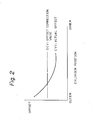
- the offset is shown in curve CV1 in Fig. 2. The offset depends on a cylinder position, and the offset is at a maximum value at an outer cylinder.
- an inspector measures the offset by observation with a synchroscope and other measuring devices, and determines a tap of the variable resistor 60 to define the offset correction value OCV shown in Fig. 2. This operation is long and troublesome.
- the offset correction value OCV is a single value, and thus does not provide an optimum offset correction for the whole cylinder position.
- variable resistor 61 is adjusted to give a seek time within a predetermined time. This requires many seek operations and measurement of seek time by changing the variable resistor 61. This operation is also long and troublesome.
- the magnetic disc drive system includes the magnetic head 51, the voice coil motor (VCM) 52, the power amplifier 53, the multiplexer 54, the current control detection circuit 55, the speed deviation calculation circuit 57, the position deviation calculation circuit 58, the speed signal generation circuit 59 and the differential circuit 62. These are substantially the same as those elements described above with reference to Fig. 1, and thus a description thereof is omitted.
- the position signal generation circuit 56 includes a servo head (not shown), an amplifier 56a, a position detection circuit 56b and a position information detection circuit 56c.
- the position detection circuit 56b detects a position of the magnetic head 51 driven by the VCM 52 on the basis of an output of the servo head, and outputs a position signal POS.
- the position information detection circuit 56c receives the position signal POS and generates a cylinder cross signal CYLINDER-CROSS and a guard band signal GUARD-BAND.
- the cylinder cross signal CYLINDER-CROSS indicates that the magnetic head 51 has moved across a cylinder.
- the guard band signal GUARD-BAND indicates that the magnetic head 51 has reached an inner guard band at which the magnetic head 51 is in a rest position.
- the magnetic disc drive system further includes an interface (I/F) control circuit 10, a microprocessor unit (MPU) 11, a random-access-memory (RAM) 12, a read-only-memory (ROM) 13, an analog-to-digital converter (ADC) 14, a speed control gain correction circuit 16, a reference speed generation circuit 17, a position offset correction circuit 18, an input register circuit 19, a timer 21 and a bus 20 interconnecting the " above elements.
- the control current ICNT is supplied to the ADC 14 through a low pass filter 15.
- the control current ICNT having an analog value is converted to a digital value at the ADC 14 and stored in the RAM 12 as a position offset.
- the I/F control circuit 10 is connected to a disc control unit 1.
- the input register circuit 19 receives the cylinder cross signal CYLINDER-CROSS and the guard band signal GUARD-BAND.
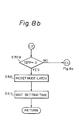
- the I/F control circuit 10 includes a seek command latch 10a receiving and holding a SEEK COMMAND from the disc control unit 1, a ready signal latch 10b holding and outputting a READY signal to the disc control unit 1, and a seek completion signal latch 10c holding and outputting a SEEK COMPLETION signal to the disc control unit 1.
- the RAM 12 includes an offset register portion 12a, a current position register portion 12b, and a difference register portion 12c.
- the offset register portion 12a has 1 to n offset registers, a first offset register saving an offset value of a first cylinder block (zone): an inner cylinder block and the n-th offset register saving an offset value of n-th cylinder block: and, an outer cylinder block.
- the current position register portion 12b stores a current position of the magnetic head 51.
- the REFERENCE POSITION is previously saved in the ROM 13.
- the CURRENT POSITION is saved in the current position register portion 12b.
- the timer 21 is used for measuring a seek time.
- the ROM 13 stores programs for performing the speed gain adjustment, the position offset adjustment, and the like. These programs are loaded to the MPU 11 and are executed therein.
- the ROM 13 also stores reference speed data 13a, cylinder position data 13b for measuring offsets, difference data 13c for testing a speed gain normal time data 13d for evaluating seek time, and reference position data 13e.
- the input register circuit 19 includes a cylinder cross signal latch 19a holding the CYLINDER CROSS signal from the position information detection circuit 56c, and a guard band signal latch 19b holding the GUARD-BAND signal.
- the speed gain correction circuit 16 includes an output register circuit 16-1 and a speed gain selector 16-2.
- the output register circuit 16-1 has a gain selection latch circuit 16a consisting of m gain selection latches, and a mode latch 16b.
- the speed gain selector 16-2 has a resistor R0, and a series-connected circuit of a switch SW1 and a resistor R1 to a series-connected circuit of a switch SWm and a resistor Rm. These are connected in parallel.
- the values of these resistors are defined by the following relationships:
- the mode latch 16b saves a MODE signal which is "1" during the seek operation or "0" during the fine control, and outputs same to the multiplexer 54.
- the reference speed generation circuit 17 consists of a digital-to-analog converter (DAC) 17a and a drive amplifier 17, and supplies the reference speed REF-SPD to the speed deviation calculation circuit 57.
- the position offset correction circuit 18 consists of a DAC 18a and a drive amplifier 18b, and outputs the position offset correction value OCV on the basis of data stored in the offset register portion 12a.
- the above adjustment will be automatically effected in response to a power ON in the magnetic disc drive system.
- the automatic position offset adjustment can be effected, and then the automatic speed gain adjustment can be effected by using the obtained offset correction values.
- the seek operation from the disc control unit 1 is inhibited.
- Fig. 6a upon power ON, the MPU 11 starts and first carries out an initialization, as shown by steps 101 to 106 (S101 to S106).
- the MPU 11 resets the ready signal latch 10b and the seek completion signal latch 10c in the I/F control circuit 10. This reset operation denotes that the magnetic disc drive system is not ready to receive a seek command, and thus, output of a seek command issued by the disk control unit 1 is inhibited.
- the MPU 11 reads a provisional offset correction value for a cylinder "0": a first cylinder, stored in the ROM 13, and stores that value in a first offset register (OFFSET REG1) of the offset register portion 12a in the RAM 12.
- the provisional offset correction value is previously obtained by experiment and is commonly used for each magnetic disc drive system.
- the MPU 11 starts a spindle motor (not shown) for rotating a magnetic disc, and waits until a speed of the spindle motor reaches a rated speed.
- the MPU 11 outputs the above transferred provisional offset correction value to the position offset correction circuit 18.
- the DAC 18a converts the received offset correction digital value into an analog signal.
- the analog signal is amplified at the driver amplifier 18b and supplied to the speed signal generation circuit 59 as a provisional offset correction value OCV.
- the MPU 11 reads a provisional speed gain selection data stored in the ROM 13 and stores that data in the RAM 12.
- the provisional speed gain selection data is previously commonly determined for magnetic disc drive systems and stored in the ROM 13.
- the MPU 11 outputs the transferred speed gain selection data to the gain selection signal latch 16a in the output register circuit 16-1.
- the switches SW1 to SWm in the speed gain selection 16-2 are energized in accordance with outputs of the gain selection signal latch 16a to define a resistance of a combination of the parallel-connected resistors RO to Rm. The resistance indicates a speed gain.
- the MPU 11 calls for a return-to-zero (RTZ) control routine and transfers a program control thereto, for moving the magnetic head 51 to a home position where a position of a cylinder is zero.
- RTZ return-to-zero
- the data stored in the first offset register OFFSET REG1 of the offset register portion 12a is output to the position offset correction circuit 18.
- a first reference speed is output to the reference speed generation circuit 17.
- the first reference speed is in a direction for moving the magnetic head 51 for an outer cylinder and a value thereof is very small compared with a normal speed value for a normal seek operation.
- the first reference speed is previously commonly determined for the magnetic disc drive systems and also previously stored in the ROM 13.
- the reference speed generation circuit 17 outputs a reference speed signal REF-SPD having a voltage corresponding to the first reference speed, through the DAC 17a and the drive amplifier 17b.
- the guard band latch 19b in the input register circuit 19 is reset.
- the mode latch 16b is set to "1" directing a start of the coarse operation: the seek operation.
- the MODE signal of "1 " is output to the multiplexer 54 to start the seek operation under the above condition.
- the position information detection circuit 56c When the magnetic head 51 reaches the guard band, the position information detection circuit 56c outputs a GUARD-BAND signal "1 ", setting the guard band latch 19b. The MPU 11 waits until the guard band latch 19b is set.
- a second reference speed is output to the reference speed generation circuit 17.
- the second reference speed is in a direction for moving the magnetic head 51 for an inner cylinder.
- the direction of the second reference speed is the reverse of that of the first reference speed.
- An amplitude of the second reference speed is equal to that of the first reference speed.
- the second reference speed is also previously determined and stored in the ROM 13. As the MODE signal is "1". the coarse control is restarted under the above conditions, and as a result, the magnetic head 51 may be moved to the inner cylinder from the guard band.
- the position information detection circuit 56c When the magnetic head 51 leaves the guard band, the position information detection circuit 56c outputs a GUARD-BAND signal "0", resetting the guard band latch 19b.
- the MPU 11 detects the leaving of the magnetic head 51 from the guard band by checking the reset of the guard band latch 19.
- a third reference speed is output to the reference speed generation circuit 17.
- the third reference speed has an amplitude smaller than that of the second reference speed, to move the magnetic head 51 more slowly.
- a direction thereof is the same as that of the second reference speed.
- the third reference speed is previously determined and stored in the ROM 13.
- the cylinder cross latch 19a in the input register circuit 19 is reset.
- the difference of the cylinder "0" is stored in the difference register portion 12c.
- the difference is two in this embodiment because the cylinder "0" is provided inside two cylinders from the guard band.
- the magnetic head 51 is moved for the inner cylinder under the third reference speed.
- the position information detection circuit 56c outputs a CYLINDER-CROSS signal "1" when the magnetic head 51 moves across a cylinder.
- the cylinder cross latch 19a is set by the CYLINDER-CROSS signal.
- the MPU 11 detects that the magnetic head 51 has moved across a cylinder by checking the setting of the cylinder cross latch 19a.
- the MPU 11 When the MPU 11 detects a move across the cylinder by the magnetic head 51, the MPU 11 resets the cylinder cross latch 19a (S212) and subtracts the difference in the difference register portion 12c by one (S213).
- the MPU 11 After completion of the placing the magnetic head 51 at the home position, the MPU 11 resets the mode latch 16b to change the mode from the coarse mode to the fine mode (S215). The MPU 11 waits for a settling time (S216), and then restores the program control to the main routine.
- the MPU 11 After completion of the RTZ control, the MPU 11 carries out the position offset adjustment shown in steps S110 to S119.
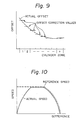
- the position offset adjustment is performed about n blocks of the cylinder zones as shown in Fig. 9.
- a dotted line shows an actual offset
- short solid lines show offset correction values for each cylinder zone.
- the MPU 11 clears the current position register portion 12b, because the magnetic head 51 is at the home position (S110).
- the MPU 11 reads a difference which indicates a distance between a measuring cylinder position of a cylinder zone 1 and the position of the cylinder "0" and is previously stored in the ROM 13, and stores it in the difference register portion 12c (S111).
- the MPU 11 sets a zone counter (not shown) in the RAM 12 to one (S112).
- the MPU 11 calls for a seek control routine for moving the magnetic head 51 to the above target cylinder, and transfers program control to the seek control routine.
- the difference stored in the difference register portion 12 is added to the current position stored in the current position register portion 12b, thus obtaining and actual target cylinder address.
- the offset correction value stored in the corresponding offset register portion 12a is output to the position offset correction circuit 18.
- the zone counter is one
- the offset correction value stored in OFFSET REG1 of the offset register portion 12a is output.
- the seek control routine is used not only for the offset adjustment and the speed gain adjustment but also for the normal seek control.
- the seek control routine is called for at step S113
- the provisional offset correction value is stored at step S102. Accordingly, the provisional offset correction value is output at this stage.
- the cylinder cross latch 19a is reset.
- the mode latch 16b is set to designate the coarse mode: the seek operation.
- the MPU 11 reads a reference speed corresponding to the difference stored in the difference register portion 12c.
- the reference speed depends on the difference as shown by dotted lines in Fig. 10.
- the reference speed curve shown in Fig. 10 is stored in the reference speed data storage portion 13a in the ROM 13 as a table.
- the MPU 11 reads a corresponding reference speed and outputs it to the reference speed generation circuit 17.
- the magnetic head 51 is moved to the target cylinder under the reference speed.
- the position information generation circuit 56c outputs the CYLINDER-CROSS signal when the magnetic head 51 means across a cylinder, and sets the cylinder cross latch 19a, the MPU 11 detects the setting of the cylinder cross latch 19a.
- the MPU 11 resets the cylinder cross latch 19a (S307), and subtracts the difference stored in the difference register 12c by one (S308).
- steps S305 to S308 are continued until the difference becomes zero (S309), at which time the magnetic head 51 is positioned at the target cylinder.
- the MPU 11 resets the mode latch 16b, thus calling for a fine mode operation (S310), and restores the program control to the main routine after waiting for a settled (setting or settling)time (S311).
- the MPU 11 reads the control current ICNT from the control current detection circuit 55 via the ADC 14 (S114). As described before, the control current ICNT indicates a position offset when the position of the magnetic head 51 is finely controlled at the target cylinder. Next, the MPU 11 calculates an actual offset correction value (S115). The calculation is effected by the following formula:
- the calculated offset correction value OCV is'stored in the corresponding OFFSET REG in the offset register portion 12a, defined by the zeon counter (S116).
- the calculated offset correction value OCV is provisionally stored in a next OFFSET REG for provisionally use in the next offset adjustment. .
- steps S113 to S116 is repeated until the zone counter reaches n (S117). If the zone counter has not reached n, the MPU 11 adds the zone counter (S118). The MPU 11 also transfers a next difference from the ROM 13 to the difference register 12c in the RAM 12 (S119), and thereafter, the MPU 11 carries out above steps S113 to S116.
- the MPU 11 carries out the speed gain adjustment as shown by steps S120 to S129.
- the MPU 11 reads a test difference from the ROM 13 and stores it in the difference register portion 12c.
- the test difference is a difference at a cylinder for adjusting the speed gain. This test difference is previously determined and stored in the ROM 13.
- the MPU 11 resets and starts the timer 21 (S121).
- the MPU 11 then calls for the seek control routine as described above with reference to Figs. 8a and 8b (S122), and as a result, the magnetic head 51 is moved to the test cylinder.
- the program control is sent to step S123.
- the MPU 11 then stops the timer 21 (S123), which indicates a seek time.
- step S125 If the measured seek time is not within a normal seek time stored in the ROM 13, the program control is transferred to step S125. When the measured seek time is longer than the normal seek time, the program control is transferred to step S126, or to step S128.
- the MPU 11 decreases the speed gain by one unit (S126). This can be effected by outputting gain selection data reduced by one to the gain selection latch 16a. Next the MPU 11 reversely changes a direction of the difference for moving the magnetic head 51 (S127), and the MPU 11 returns to step S121 to repeat the seek time measurement.
- the MPU 11 increases the speed gain by one unit (S128), and reversely changes the direction of the difference (S129). The MPU 11 then returns to step S121 to measure the seek time.
- the MPU 11 calculates a difference to move the magnetic head 51 to the cylinder "0": the home position, and stores it in the difference register portion (S131). The MPU 11 then calls for the seek control routine (S132), and as a result, the magnetic head 51 is moved at the cylinder "0".
- the MPU 11 then sets the ready latch 10b and the seek completion latch 10c (S133), and thus the adjustment is completed.
- the disk control unit 1 Upon receipt of the READY signal from the ready latch 10b and the SEEK COMPLETION signal from the seek completion latch 10c, the disk control unit 1 outputs a normal seek command.
- the normal seek command control is carried out by using the offset correction value and the adjusted speed control gain.
- Figure 11 shows the seek command control procedure. Note, the seek command control, per se, is known, and thus a description thereof is omitted.
- steps S113 to S116 shown in Fig. 6b can be repeated for each cylinder zone, and each offset correction value can be averaged for a several calculated offset correction value for each cylinder zone.
- the operation of the seek time measurement and the determination of the speed control gain can be repeated, and a final speed gain can be averaged for several adjusted speed control gains.
- the above repetition should be limited to a reasonable time, because of the need for a shortening of the adjustment time.
- the present invention naturally provides the offset correction adjustment and/or the speed control gain adjustment. Also, in the above offset correction adjustment, the adjustment was effected for a plurality of cylinder zones, as shown in Fig. 9, to achieve an optimum offset correction. However, to reduce the adjustment time, the adjustment for a single cylinder, as shown in Fig. 2, can be carried out.
Abstract
Description
- The present invention relates to a magnetic disc system. More particularly, it relates to a magnetic disc drive system in the magnetic disc system
- A magnetic disc mechanism has an offset based on the characteristics of a spring provided for restoring magnetic heads to a rest position during a stop mode, and the characteristics of a voice coil motor (VCM) as an actuator for driving the magnetic heads. To realize a precise seek (speed) control and a s precise position control, an offset correction must be made. The offset depends on the individual magnetic disc mechanism, and thus, before shipping a magnetic disc system, a measurement of the offset and a determination of an offset correction value must be carried out for each magnetic disc system.
- A speed control gain also depends on the individual magnetic disc system, and accordingly, before shipping the magnetic disc system, a determination of an optimum speed control gain for each magnetic disc system must be carried out.
- In a prior art, the offset measurement and the offset correction value determination are manually effected, thus having the disadvantages of a troublesome manual operation and a long adjustment time. Similarly, the determination of the optimum speed control gain is manually effected, and thus also has the same disadvantages.
- In addition, if a problem, which may require a replacement of parts and thus requires a repeat of the above adjustment occurs at site, the adjustment process must be carried out at site.
- The offset of every magnetic disc mechanism depends on a position of cylinders. However, in the prior art, only a single offset correction value is determined. As a result, an optimum offset correction for all cylinders cannot be achieved.
- An embodiment of the present invention may provide a magnetic disc drive system having a means for automatically adjusting an offset and a speed control gain.
- An embodiment of the present invention may also provide a magnetic disc drive system which carries out an optimum offset correction, in addition to the above automatic adjustment.
- According to the present invention, there is provided a magnetic disc drive system including: a magnetic head; an actuator for moving the magnetic head; a control current detection circuit for detecting a control current flowing through the actuator; a position signal generation circuit for generating a position signal of the magnetic head; a speed control unit for effecting a seek control; a position control unit for effecting a fine position control after completion of the seek control; and means, operatively connected to the speed control unit, the position control unit, the control current detection circuit and the position signal generation circuit, and operating immediately upon receipt of a power supply and before receipt of a seek command, for measuring one or more position offset values along one or more cylinders on a magnetic disc by detecting the control current from the control current detection circuit when the position of the magnetic head is controlled under the fine position control, and calculating one or more offset corrections values and outputting the calculated offset correction values to the speed control unit and the position control unit.
- Following the offset correction calculation, a seek control for a normal seek command can be carried out by using the calculated offset correction values. Also, a fine position control after completion of the normal seek control can be carried out by using the calculated offset correction values.
- The magnetic disc drive system may further include means, operatively connected to the speed control unit and the position signal generation circuit, for determining, after completion of the offset correction value calculation by the offset adjustment means, a speed control gain used in the speed control unit by seeking the magnetic head at a predetermined cylinder under application of the calculated offset values and by measuring a time for the seek which meets a requirement of a reference seek time. After completion of the speed control gain adjustment, a seek control for a normal seek command can be carried out by using the adjusted speed control gain.
- The speed control gain adjustment means may include a plurality of resistors connected in parallel by a _ plurality of switches each serially connected to a corresponding resistor. The resistors may have a predetermined relationship of respective resistance values, and a combination of the resistances of the parallel-connected resistors defines the speed control gain.
- The offset adjustment can be carried out along a plurality of cylinder zones.
- Embodiments of the present invention will be described below in detail with reference to the accompanying drawings, in which:
- Fig. 1 is a view of a prior art magnetic disc drive system;
- Fig. 2 is a graph representing an offset correction value of the prior art;
- Fig. 3 is a diagram of an embodiment of a magnetic disc drive system in accordance with the present invention;
- Figs. 4 and 5 are detailed diagrams representing a part of the magnetic disc drive system shown in Fig. 3;
- Figs. 6a to 6e are flow charts explaining an offset correction adjustment and a speed control gain adjustment which are carried out by the magnetic disc drive system shown in Figs. 3 to 5;
- Figs. 7a and 7b are flow charts explaining a return to zero control applied in the magnetic disc drive system;
- Figs. 8a and 8b are flow charts explaining a seek control applied in the magnetic disc drive system;
- Fig. 9 is a graph representing offset correction values obtained by the magnetic disc drive system;
- Fig. 10 is a graph representing a speed control curve applied in the magnetic disc drive system; and
- Fig. 11 is a flow chart explaining a seek command control applied in the magnetic disc drive system.
- Before describing the preferred embodiments of the present invention, an example of a prior art magnetic disc drive system is described with reference to the drawings, for comparison.
- Figure 1 shows a prior art magnetic drive system. In Fig. 1,
reference 51 denotes a magnetic head, 52 a voice coil motor (VCM), 53 a power amplifier, 54 a multiplexer, 55 a control current detection circuit, 56 a position signal generation circuit, 57 a speed deviation calculation circuit, 58 a position deviation calculation circuit, 59 a speed signal generation circuit, 60 a position offset adjustment circuit, 61 a speed control gain adjustment circuit, and 62 a differential circuit. - The
multiplexer 54 selects an output from the speeddeviation calculation circuit 57 when a MODE signal is "1", indicating a coarse control, i.e., a seek control, or an output from the positiondeviation calculation circuit 58 when the MODE signal is "0", indicating a fine control, i.e., a position control after completion of the seek control. The controlcurrent detection circuit 55 detects a current flowing through theVCM 52 and generates a control current ICNT. The positionsignal generation circuit 56 detects a position of thehead 51 and generates a position signal POS, a cylinder cross signal and a guard band signal. Thedifferential circuit 62 differentiates the position signal POS from the positionsignal generation circuit 56 and provides a raw speed signal Vr. The speedsignal generation circuit 59 receives the control current ICNT, a position offset correction value OCV from the positionoffset adjustment circuit 60, and a speed signal Vr' which is gain-adjusted at the speedgain adjustment circuit 61 to the raw speed signal Vr, and generates a corrected actual speed signal ACT-SPD. The speeddeviation calculation circuit 57 receives a reference (or target) speed REF-SPD and the corrected actual speed signal ACT-SPD, calculates a speed deviation ΔV: (REF-SPD) - (ACT-SPD), and outputs same to themultiplexer 54. The positiondeviation calculation circuit 58 receives the control current signal ICNT, the position offset correction value OCV, and the position signal POS, calculates a position deviation AP, and outputs same to themultiplexer 54. - The position
offset adjustment circuit 60 is formed by a variable resistor connected between a + 5 V power supply and a -12 V power supply. The speed controlgain adjustment circuit 61 is also formed by a variable resistor. - The control current ICNT under the fine control mode indicates a position offset. This because, under the fine control mode, a position error is very small and the current flowing through the
VCM 52 should be zero, but if a current flows into theVCM 52 it is used for keeping the magnetic head at the target cylinder position and resisting a force of a spring (not shown) mechanically connected to themagnetic head 51. Therefore the offset is obtained by measuring the control current. The offset is shown in curve CV1 in Fig. 2. The offset depends on a cylinder position, and the offset is at a maximum value at an outer cylinder. - In a prior art, an inspector measures the offset by observation with a synchroscope and other measuring devices, and determines a tap of the
variable resistor 60 to define the offset correction value OCV shown in Fig. 2. This operation is long and troublesome. In addition, the offset correction value OCV is a single value, and thus does not provide an optimum offset correction for the whole cylinder position. - The
variable resistor 61 is adjusted to give a seek time within a predetermined time. This requires many seek operations and measurement of seek time by changing thevariable resistor 61. This operation is also long and troublesome. - Now, a preferred embodiment of a magnetic disc drive system in accordance with the present invention will be described.
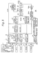
- Referring to Fig. 3, the magnetic disc drive system includes the
magnetic head 51, the voice coil motor (VCM) 52, thepower amplifier 53, themultiplexer 54, the currentcontrol detection circuit 55, the speeddeviation calculation circuit 57, the positiondeviation calculation circuit 58, the speedsignal generation circuit 59 and thedifferential circuit 62. These are substantially the same as those elements described above with reference to Fig. 1, and thus a description thereof is omitted. - The position
signal generation circuit 56 includes a servo head (not shown), anamplifier 56a, aposition detection circuit 56b and a positioninformation detection circuit 56c. Theposition detection circuit 56b detects a position of themagnetic head 51 driven by theVCM 52 on the basis of an output of the servo head, and outputs a position signal POS. The positioninformation detection circuit 56c receives the position signal POS and generates a cylinder cross signal CYLINDER-CROSS and a guard band signal GUARD-BAND. The cylinder cross signal CYLINDER-CROSS indicates that themagnetic head 51 has moved across a cylinder. The guard band signal GUARD-BAND indicates that themagnetic head 51 has reached an inner guard band at which themagnetic head 51 is in a rest position. - The magnetic disc drive system further includes an interface (I/F)
control circuit 10, a microprocessor unit (MPU) 11, a random-access-memory (RAM) 12, a read-only-memory (ROM) 13, an analog-to-digital converter (ADC) 14, a speed controlgain correction circuit 16, a referencespeed generation circuit 17, a position offsetcorrection circuit 18, aninput register circuit 19, atimer 21 and abus 20 interconnecting the " above elements. The control current ICNT is supplied to theADC 14 through alow pass filter 15. The control current ICNT having an analog value is converted to a digital value at theADC 14 and stored in theRAM 12 as a position offset. The I/F control circuit 10 is connected to adisc control unit 1. Theinput register circuit 19 receives the cylinder cross signal CYLINDER-CROSS and the guard band signal GUARD-BAND. - Referring to Figs. 4 and 5, a more specific circuit construction will be described.
- In Fig. 4, the I/
F control circuit 10 includes a seek command latch 10a receiving and holding a SEEK COMMAND from thedisc control unit 1, aready signal latch 10b holding and outputting a READY signal to thedisc control unit 1, and a seekcompletion signal latch 10c holding and outputting a SEEK COMPLETION signal to thedisc control unit 1. TheRAM 12 includes an offset register portion 12a, a currentposition register portion 12b, and adifference register portion 12c. The offset register portion 12a has 1 to n offset registers, a first offset register saving an offset value of a first cylinder block (zone): an inner cylinder block and the n-th offset register saving an offset value of n-th cylinder block: and, an outer cylinder block. These offset values are input through theADC 14. The currentposition register portion 12b stores a current position of themagnetic head 51. Thedifference register portion 12c saves a position difference AD of themagnetic head 1 to a position of a target cylinder: AD = (REFERENCE POSITION) - (CURRENT POSITION). The REFERENCE POSITION is previously saved in theROM 13. The CURRENT POSITION is saved in the currentposition register portion 12b. Thetimer 21 is used for measuring a seek time. TheROM 13 stores programs for performing the speed gain adjustment, the position offset adjustment, and the like. These programs are loaded to theMPU 11 and are executed therein. TheROM 13 also storesreference speed data 13a,cylinder position data 13b for measuring offsets,difference data 13c for testing a speed gainnormal time data 13d for evaluating seek time, and reference position data 13e. Theinput register circuit 19 includes a cylinder cross signal latch 19a holding the CYLINDER CROSS signal from the positioninformation detection circuit 56c, and a guardband signal latch 19b holding the GUARD-BAND signal. - In Fig. 5, the speed
gain correction circuit 16 includes an output register circuit 16-1 and a speed gain selector 16-2. The output register circuit 16-1 has a gainselection latch circuit 16a consisting of m gain selection latches, and amode latch 16b. The speed gain selector 16-2 has a resistor R0, and a series-connected circuit of a switch SW1 and a resistor R1 to a series-connected circuit of a switch SWm and a resistor Rm. These are connected in parallel. The values of these resistors are defined by the following relationships: - R1 = 2.RO
- R2 = 2.R1
- •
- •
- Rm = 2*Rm-1
- The switches SW1 to SWm are independently energized by outputs from the gain selection latches. If m = 4, the speed gain can be varied between 1 and 32. The
mode latch 16b saves a MODE signal which is "1" during the seek operation or "0" during the fine control, and outputs same to themultiplexer 54. The referencespeed generation circuit 17 consists of a digital-to-analog converter (DAC) 17a and adrive amplifier 17, and supplies the reference speed REF-SPD to the speeddeviation calculation circuit 57. The position offsetcorrection circuit 18 consists of a DAC 18a and adrive amplifier 18b, and outputs the position offset correction value OCV on the basis of data stored in the offset register portion 12a. - The automatic position offset adjustment and the automatic speed gain adjustment of the magnetic disc drive system shown in Figs. 3 to 5 will be described.
- The above adjustment will be automatically effected in response to a power ON in the magnetic disc drive system. First, the automatic position offset adjustment can be effected, and then the automatic speed gain adjustment can be effected by using the obtained offset correction values. During the adjustment, the seek operation from the
disc control unit 1 is inhibited. - A more concrete description of the operation will be given with reference to Figs. 6a to 10.
- In Fig. 6a, upon power ON, the
MPU 11 starts and first carries out an initialization, as shown by steps 101 to 106 (S101 to S106). - The
MPU 11 resets theready signal latch 10b and the seekcompletion signal latch 10c in the I/F control circuit 10. This reset operation denotes that the magnetic disc drive system is not ready to receive a seek command, and thus, output of a seek command issued by thedisk control unit 1 is inhibited. - The
MPU 11 reads a provisional offset correction value for a cylinder "0": a first cylinder, stored in theROM 13, and stores that value in a first offset register (OFFSET REG1) of the offset register portion 12a in theRAM 12. The provisional offset correction value is previously obtained by experiment and is commonly used for each magnetic disc drive system. - The
MPU 11 starts a spindle motor (not shown) for rotating a magnetic disc, and waits until a speed of the spindle motor reaches a rated speed. - The
MPU 11 outputs the above transferred provisional offset correction value to the position offsetcorrection circuit 18. In the position offsetcorrection circuit 18, the DAC 18a converts the received offset correction digital value into an analog signal. The analog signal is amplified at thedriver amplifier 18b and supplied to the speedsignal generation circuit 59 as a provisional offset correction value OCV. - The
MPU 11 reads a provisional speed gain selection data stored in theROM 13 and stores that data in theRAM 12. The provisional speed gain selection data is previously commonly determined for magnetic disc drive systems and stored in theROM 13. - The
MPU 11 outputs the transferred speed gain selection data to the gainselection signal latch 16a in the output register circuit 16-1. The switches SW1 to SWm in the speed gain selection 16-2 are energized in accordance with outputs of the gainselection signal latch 16a to define a resistance of a combination of the parallel-connected resistors RO to Rm. The resistance indicates a speed gain. - The
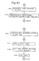
MPU 11 calls for a return-to-zero (RTZ) control routine and transfers a program control thereto, for moving themagnetic head 51 to a home position where a position of a cylinder is zero. - The RTZ control will be described with reference to Figs. 7a and 7b.
- The data stored in the first offset register OFFSET REG1 of the offset register portion 12a is output to the position offset
correction circuit 18. - A first reference speed is output to the reference
speed generation circuit 17. The first reference speed is in a direction for moving themagnetic head 51 for an outer cylinder and a value thereof is very small compared with a normal speed value for a normal seek operation. The first reference speed is previously commonly determined for the magnetic disc drive systems and also previously stored in theROM 13. The referencespeed generation circuit 17 outputs a reference speed signal REF-SPD having a voltage corresponding to the first reference speed, through theDAC 17a and the drive amplifier 17b. - The
guard band latch 19b in theinput register circuit 19 is reset. - The
mode latch 16b is set to "1" directing a start of the coarse operation: the seek operation. The MODE signal of "1 " is output to themultiplexer 54 to start the seek operation under the above condition. - When the
magnetic head 51 reaches the guard band, the positioninformation detection circuit 56c outputs a GUARD-BAND signal "1 ", setting theguard band latch 19b. TheMPU 11 waits until theguard band latch 19b is set. - A second reference speed is output to the reference
speed generation circuit 17. The second reference speed is in a direction for moving themagnetic head 51 for an inner cylinder. In other words, the direction of the second reference speed is the reverse of that of the first reference speed. An amplitude of the second reference speed is equal to that of the first reference speed. The second reference speed is also previously determined and stored in theROM 13. As the MODE signal is "1". the coarse control is restarted under the above conditions, and as a result, themagnetic head 51 may be moved to the inner cylinder from the guard band. - When the
magnetic head 51 leaves the guard band, the positioninformation detection circuit 56c outputs a GUARD-BAND signal "0", resetting theguard band latch 19b. TheMPU 11 detects the leaving of themagnetic head 51 from the guard band by checking the reset of theguard band latch 19. - A third reference speed is output to the reference
speed generation circuit 17. The third reference speed has an amplitude smaller than that of the second reference speed, to move themagnetic head 51 more slowly. A direction thereof is the same as that of the second reference speed. The third reference speed is previously determined and stored in theROM 13. - The cylinder cross latch 19a in the
input register circuit 19 is reset. - The difference of the cylinder "0" is stored in the
difference register portion 12c. The difference is two in this embodiment because the cylinder "0" is provided inside two cylinders from the guard band. - The
magnetic head 51 is moved for the inner cylinder under the third reference speed. The positioninformation detection circuit 56c outputs a CYLINDER-CROSS signal "1" when themagnetic head 51 moves across a cylinder. The cylinder cross latch 19a is set by the CYLINDER-CROSS signal. TheMPU 11 detects that themagnetic head 51 has moved across a cylinder by checking the setting of the cylinder cross latch 19a. - When the
MPU 11 detects a move across the cylinder by themagnetic head 51, theMPU 11 resets the cylinder cross latch 19a (S212) and subtracts the difference in thedifference register portion 12c by one (S213). - The steps S211 to S213 are continued until the difference becomes zero, i.e., until the
magnetic head 51 reaches the cylinder "0": the home position. - After completion of the placing the
magnetic head 51 at the home position, theMPU 11 resets themode latch 16b to change the mode from the coarse mode to the fine mode (S215). TheMPU 11 waits for a settling time (S216), and then restores the program control to the main routine. - After completion of the RTZ control, the
MPU 11 carries out the position offset adjustment shown in steps S110 to S119. The position offset adjustment is performed about n blocks of the cylinder zones as shown in Fig. 9. In Fig. 9, a dotted line shows an actual offset, and short solid lines show offset correction values for each cylinder zone. - The
MPU 11 clears the currentposition register portion 12b, because themagnetic head 51 is at the home position (S110). TheMPU 11 reads a difference which indicates a distance between a measuring cylinder position of acylinder zone 1 and the position of the cylinder "0" and is previously stored in theROM 13, and stores it in thedifference register portion 12c (S111). TheMPU 11 sets a zone counter (not shown) in theRAM 12 to one (S112). - The
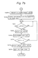
MPU 11 calls for a seek control routine for moving themagnetic head 51 to the above target cylinder, and transfers program control to the seek control routine. - The seek control will be briefly described with reference to Figs. 8a and 8b.
- The difference stored in the
difference register portion 12 is added to the current position stored in the currentposition register portion 12b, thus obtaining and actual target cylinder address. - The offset correction value stored in the corresponding offset register portion 12a is output to the position offset
correction circuit 18. When the zone counter is one, the offset correction value stored in OFFSET REG1 of the offset register portion 12a is output. The seek control routine is used not only for the offset adjustment and the speed gain adjustment but also for the normal seek control. When the seek control routine is called for at step S113, the provisional offset correction value is stored at step S102. Accordingly, the provisional offset correction value is output at this stage. - The cylinder cross latch 19a is reset.
- The
mode latch 16b is set to designate the coarse mode: the seek operation. - The
MPU 11 reads a reference speed corresponding to the difference stored in thedifference register portion 12c. The reference speed depends on the difference as shown by dotted lines in Fig. 10. The reference speed curve shown in Fig. 10 is stored in the reference speeddata storage portion 13a in theROM 13 as a table. TheMPU 11 reads a corresponding reference speed and outputs it to the referencespeed generation circuit 17. - The
magnetic head 51 is moved to the target cylinder under the reference speed. - The position
information generation circuit 56c outputs the CYLINDER-CROSS signal when themagnetic head 51 means across a cylinder, and sets the cylinder cross latch 19a, theMPU 11 detects the setting of the cylinder cross latch 19a. - The
MPU 11 resets the cylinder cross latch 19a (S307), and subtracts the difference stored in thedifference register 12c by one (S308). - The above operations of steps S305 to S308 are continued until the difference becomes zero (S309), at which time the
magnetic head 51 is positioned at the target cylinder. - The
MPU 11 resets themode latch 16b, thus calling for a fine mode operation (S310), and restores the program control to the main routine after waiting for a settled (setting or settling)time (S311). - The
MPU 11 reads the control current ICNT from the controlcurrent detection circuit 55 via the ADC 14 (S114). As described before, the control current ICNT indicates a position offset when the position of themagnetic head 51 is finely controlled at the target cylinder. Next, theMPU 11 calculates an actual offset correction value (S115). The calculation is effected by the following formula: - where,
- OCV: a calculated offset correction value,
- ICNTR: a read of the control current, and
- a: a circuit gain.
- The calculated offset correction value OCV is'stored in the corresponding OFFSET REG in the offset register portion 12a, defined by the zeon counter (S116). The calculated offset correction value OCV is provisionally stored in a next OFFSET REG for provisionally use in the next offset adjustment. .
- The operation of steps S113 to S116 is repeated until the zone counter reaches n (S117). If the zone counter has not reached n, the
MPU 11 adds the zone counter (S118). TheMPU 11 also transfers a next difference from theROM 13 to thedifference register 12c in the RAM 12 (S119), and thereafter, theMPU 11 carries out above steps S113 to S116. - If the zone counter reaches n, the offset adjustment is completed, and then the
MPU 11 carries out the speed gain adjustment as shown by steps S120 to S129. - The
MPU 11 reads a test difference from theROM 13 and stores it in thedifference register portion 12c. The test difference is a difference at a cylinder for adjusting the speed gain. This test difference is previously determined and stored in theROM 13. - The
MPU 11 resets and starts the timer 21 (S121). TheMPU 11 then calls for the seek control routine as described above with reference to Figs. 8a and 8b (S122), and as a result, themagnetic head 51 is moved to the test cylinder. After completion of the seek control, the program control is sent to step S123. TheMPU 11 then stops the timer 21 (S123), which indicates a seek time. - If the measured seek time is not within a normal seek time stored in the
ROM 13, the program control is transferred to step S125. When the measured seek time is longer than the normal seek time, the program control is transferred to step S126, or to step S128. - The
MPU 11 decreases the speed gain by one unit (S126). This can be effected by outputting gain selection data reduced by one to thegain selection latch 16a. Next theMPU 11 reversely changes a direction of the difference for moving the magnetic head 51 (S127), and theMPU 11 returns to step S121 to repeat the seek time measurement. - The
MPU 11 increases the speed gain by one unit (S128), and reversely changes the direction of the difference (S129). TheMPU 11 then returns to step S121 to measure the seek time. - The above steps S126 and S127 or the steps S128 and S129 are repeated until the seek time is within the normal seek time (S124).
- When the measured seek time is within the normal seek time, the speed gain is automatically adjusted to meet the requirements of the seek control under the adjusted offset correction values. Then, the
MPU 11 calculates a difference to move themagnetic head 51 to the cylinder "0": the home position, and stores it in the difference register portion (S131). TheMPU 11 then calls for the seek control routine (S132), and as a result, themagnetic head 51 is moved at the cylinder "0". - The
MPU 11 then sets theready latch 10b and the seekcompletion latch 10c (S133), and thus the adjustment is completed. - Upon receipt of the READY signal from the
ready latch 10b and the SEEK COMPLETION signal from the seekcompletion latch 10c, thedisk control unit 1 outputs a normal seek command. - The normal seek command control is carried out by using the offset correction value and the adjusted speed control gain. Figure 11 shows the seek command control procedure. Note, the seek command control, per se, is known, and thus a description thereof is omitted.
- To improve the accuracy of the offset correction values, the operation of steps S113 to S116 shown in Fig. 6b can be repeated for each cylinder zone, and each offset correction value can be averaged for a several calculated offset correction value for each cylinder zone. Similarly, the operation of the seek time measurement and the determination of the speed control gain can be repeated, and a final speed gain can be averaged for several adjusted speed control gains. However, the above repetition should be limited to a reasonable time, because of the need for a shortening of the adjustment time.
- In the above embodiment, a combination of the offset correction adjustment and the speed control gain adjustment is described. The present invention naturally provides the offset correction adjustment and/or the speed control gain adjustment. Also, in the above offset correction adjustment, the adjustment was effected for a plurality of cylinder zones, as shown in Fig. 9, to achieve an optimum offset correction. However, to reduce the adjustment time, the adjustment for a single cylinder, as shown in Fig. 2, can be carried out.
- Many widely different embodiments of the present invention may be constructed without departing from the spirit and scope of the present invention. It should be understood that the present invention is not limited to the specific embodiments described in this specification, except as defined in the appended claims.
Claims (5)
and after completion of said speed control gain adjustment, a seek control for a normal seek command being carried out by using said adjusted speed control gain.
Applications Claiming Priority (2)
| Application Number | Priority Date | Filing Date | Title |
|---|---|---|---|
| JP61299594A JP2612262B2 (en) | 1986-12-16 | 1986-12-16 | Magnetic disk device |
| JP299594/86 | 1986-12-16 |
Publications (3)
| Publication Number | Publication Date |
|---|---|
| EP0272076A2 true EP0272076A2 (en) | 1988-06-22 |
| EP0272076A3 EP0272076A3 (en) | 1990-03-14 |
| EP0272076B1 EP0272076B1 (en) | 1992-05-13 |
Family
ID=17874656
Family Applications (1)
| Application Number | Title | Priority Date | Filing Date |
|---|---|---|---|
| EP87311001A Expired - Lifetime EP0272076B1 (en) | 1986-12-16 | 1987-12-15 | Magnetic disc drive system |
Country Status (5)
| Country | Link |
|---|---|
| US (1) | US4907109A (en) |
| EP (1) | EP0272076B1 (en) |
| JP (1) | JP2612262B2 (en) |
| KR (1) | KR910003198B1 (en) |
| DE (1) | DE3779071D1 (en) |
Cited By (9)
| Publication number | Priority date | Publication date | Assignee | Title |
|---|---|---|---|---|
| EP0357044A1 (en) * | 1988-09-02 | 1990-03-07 | Sharp Kabushiki Kaisha | Device for controlling an access operation of an information recording and reproducing device |
| GB2225455A (en) * | 1988-10-12 | 1990-05-30 | Pioneer Electronic Corp | Loop-gain control system in a spindle servo loop |
| EP0378328A2 (en) * | 1989-01-10 | 1990-07-18 | Fujitsu Limited | Servo positioning circuit |
| EP0378331A2 (en) * | 1989-01-10 | 1990-07-18 | Fujitsu Limited | Servo circuit |
| EP0378327A2 (en) * | 1989-01-10 | 1990-07-18 | Fujitsu Limited | Automatic adjustment system for servo circuit of a magnetic disk apparatus |
| EP0378329A2 (en) * | 1989-01-10 | 1990-07-18 | Fujitsu Limited | Servo circuit for magnetic disk apparatus |
| EP0381314A2 (en) * | 1989-01-30 | 1990-08-08 | Fujitsu Limited | Servo circuit |
| EP0456371A2 (en) * | 1990-04-30 | 1991-11-13 | Seagate Technology International | Method of controlling seek movements by a magnetic head in a hard disk drive |
| EP0478312A2 (en) * | 1990-09-27 | 1992-04-01 | International Business Machines Corporation | Optical disk drive initialisation method |
Families Citing this family (54)
| Publication number | Priority date | Publication date | Assignee | Title |
|---|---|---|---|---|
| JPH0814950B2 (en) * | 1987-09-14 | 1996-02-14 | 株式会社日立製作所 | Head positioning method for magnetic disk drive |
| JPH0814945B2 (en) * | 1988-04-06 | 1996-02-14 | 株式会社東芝 | Magnetic head movement control device for magnetic disk device |
| JPH0210580A (en) * | 1988-06-28 | 1990-01-16 | Nec Corp | Disk control device |
| JPH02118979A (en) * | 1988-10-26 | 1990-05-07 | Sony Corp | Head positioning controller for disk drive |
| JPH0736128B2 (en) * | 1989-01-10 | 1995-04-19 | 富士通株式会社 | Servo circuit speed detection gain automatic adjustment method |
| JPH0736133B2 (en) * | 1989-01-10 | 1995-04-19 | 富士通株式会社 | Servo circuit access time automatic adjustment method |
| JPH0736129B2 (en) * | 1989-01-10 | 1995-04-19 | 富士通株式会社 | Position control offset adjustment method for servo circuit |
| JPH0736127B2 (en) * | 1989-01-10 | 1995-04-19 | 富士通株式会社 | Servo circuit position control switching control method |
| US5359581A (en) * | 1989-07-04 | 1994-10-25 | Canon Kabushiki Kaisha | Detector for moving velocity of light beam spot |
| US5301174A (en) * | 1989-07-14 | 1994-04-05 | Sharp Kabushiki Kaisha | Optical disk recording and reproducing apparatus |
| US5033039A (en) * | 1989-07-31 | 1991-07-16 | Literal Corporation | Positioning system for flexure mounted read/write head |
| JPH0782023B2 (en) * | 1990-03-19 | 1995-09-06 | ティアツク株式会社 | Motor speed detector |
| US5265077A (en) * | 1990-07-16 | 1993-11-23 | Mitsubishi Electric Corporation | Optical disk storage having reduced power consumption during seeking operations |
| DE69130762T2 (en) * | 1990-09-18 | 1999-09-09 | Rodime Plc | DIGITAL SERVO CONTROL FOR A DISK DRIVE |
| US5157666A (en) * | 1990-09-24 | 1992-10-20 | Xerox Corporation | Disk timing diagnostic |
| JP2642518B2 (en) * | 1990-12-21 | 1997-08-20 | 富士通株式会社 | Offset correction method for magnetic head position signal |
| JP2634489B2 (en) * | 1990-12-21 | 1997-07-23 | 富士通株式会社 | Magnetic disk drive |
| JP3173804B2 (en) * | 1990-12-25 | 2001-06-04 | 富士通株式会社 | Magnetic disk drive |
| US5657179A (en) * | 1991-03-28 | 1997-08-12 | Seagate Technology, Inc. | Method for reducing noise during track seeking in a disc drive |
| US5475545A (en) * | 1991-03-28 | 1995-12-12 | Seagate Technology, Inc. | Method for reducing noise during seeks in a hard disk drive |
| AU2304392A (en) * | 1991-06-26 | 1993-01-25 | Maxtor Corporation | Method and apparatus for detecting data track misregistration |
| US5305160A (en) * | 1991-07-31 | 1994-04-19 | Seagate Technology, Inc. | Compensating for variations in torque capability of voice coil motors |
| JP2647291B2 (en) * | 1991-10-16 | 1997-08-27 | インターナショナル・ビジネス・マシーンズ・コーポレイション | Method for positioning head of recording apparatus at high speed |
| US5381282A (en) * | 1991-10-18 | 1995-01-10 | International Business Machines Corporation | Inter-sample switching of servo control in direct access storage devices |
| JP3248220B2 (en) * | 1992-03-18 | 2002-01-21 | 株式会社日立製作所 | Disk device and control method thereof |
| JP2608223B2 (en) * | 1992-03-19 | 1997-05-07 | 富士通株式会社 | Actuator torque correction method |
| JP2635262B2 (en) * | 1992-03-31 | 1997-07-30 | 富士通株式会社 | Positioning control device used for magnetic disk drive |
| JPH05314691A (en) * | 1992-05-06 | 1993-11-26 | Toshiba Corp | Magnetic disk device |
| US5805374A (en) * | 1992-10-16 | 1998-09-08 | International Business Machines Corporation | Method and apparatus for fast positioning a head of a recording device |
| US5729397A (en) * | 1992-12-31 | 1998-03-17 | International Business Machines Corporation | System and method for recording direct access storage device operating statistics |
| US5408367A (en) * | 1993-09-20 | 1995-04-18 | Integral Peripherals, Inc. | Method of optimizing operation of disk drive |
| JP2680260B2 (en) * | 1994-02-14 | 1997-11-19 | インターナショナル・ビジネス・マシーンズ・コーポレイション | Disk storage device and head control device |
| US5696647A (en) * | 1994-03-28 | 1997-12-09 | Seagate Technology, Inc. | Method for carrying out seeks in a hard disc drive to limit the generation of acoustic noise including using a slew rate limit |
| KR100277073B1 (en) * | 1995-07-24 | 2001-01-15 | 윤종용 | The velocity and position estimator of a magnetic head in a magnetic disk drive |
| KR100251920B1 (en) * | 1995-11-07 | 2000-04-15 | 윤종용 | Initialization method of hdd with self tunning method |
| US6031684A (en) * | 1997-06-03 | 2000-02-29 | Seagate Technology, Inc. | Servo gain optimization using model reference seeks in a disc drive |
| US6266203B1 (en) | 1997-06-13 | 2001-07-24 | Seagate Technology Llc | Integrated temperature sense circuit in a disc drive |
| JP2002513499A (en) * | 1997-06-13 | 2002-05-08 | シーゲイト テクノロジー エルエルシー | Temperature dependent disk drive parametric configuration |
| US6490120B1 (en) | 1997-08-29 | 2002-12-03 | Seagate Technology Llc | Servo gain optimization using a variable convergence factor |
| US6252731B1 (en) | 1997-10-16 | 2001-06-26 | Seagate Technology Llc | Parametric optimization using disc drive read channel quality measurements |
| JPH11178383A (en) * | 1997-12-04 | 1999-07-02 | Toshiba Corp | Motor controller |
| US6570733B1 (en) | 1998-01-13 | 2003-05-27 | Seagate Technology Llc | Adaptive servo gain adjustment to improve disc drive seek performance |
| KR100518514B1 (en) * | 1998-02-20 | 2005-11-24 | 삼성전자주식회사 | Actuator on-track control device and method in hard disk drive |
| US6169382B1 (en) | 1998-07-02 | 2001-01-02 | Seagate Technology Llc | Adapting seek velocity profile to destination track location |
| US6449117B1 (en) | 1998-07-13 | 2002-09-10 | Seagate Technology Llc | Reducing acoustic noise using a current profile during initial stages of a disc drive seek |
| DE19983364T1 (en) | 1998-07-13 | 2001-06-13 | Seagate Technology | Power profile shaping to reduce disk drive seek time variation and acoustic noise generation |
| US6268974B1 (en) | 1998-07-13 | 2001-07-31 | Seagate Technology Llc | Gain optimization in a disc drive |
| US6538840B1 (en) * | 1999-01-30 | 2003-03-25 | Seagate Technology Llc | Automatic method for optimizing throughput in a disc drive |
| US6744702B2 (en) * | 2000-09-29 | 2004-06-01 | Kabushiki Kaisha Toshiba | Apparatus for accessing recording disk by controlling the coarse and precise actuators |
| US6731453B2 (en) | 2001-02-15 | 2004-05-04 | Seagate Technology Llc | Optimizing thermal performance of an integrated circuit in a disc drive |
| US6747838B2 (en) | 2001-02-15 | 2004-06-08 | Seagate Technology Llc | Thermal performance of an integrated amplifier in a disc drive |
| US6574070B2 (en) | 2001-08-09 | 2003-06-03 | Seagate Technology Llc | Model reference generator for a disc drive |
| US20050034539A1 (en) * | 2003-08-14 | 2005-02-17 | Tan Leeling | Motor torque variation compensation |
| US7012780B1 (en) * | 2004-09-02 | 2006-03-14 | Maxtor Corporation | Disk drive and methods that calibrate micro actuator positioning before seek operations |
Citations (2)
| Publication number | Priority date | Publication date | Assignee | Title |
|---|---|---|---|---|
| US4419701A (en) * | 1981-09-21 | 1983-12-06 | Quantum Corporation | Data transducer position control system for rotating disk data storage equipment |
| EP0111665A1 (en) * | 1982-12-20 | 1984-06-27 | International Business Machines Corporation | Automatic reference adjustment for position error signal on disk file servo system |
Family Cites Families (7)
| Publication number | Priority date | Publication date | Assignee | Title |
|---|---|---|---|---|
| JPS4968708A (en) * | 1972-11-01 | 1974-07-03 | ||
| JPS50125705A (en) * | 1974-03-19 | 1975-10-03 | ||
| US4135217A (en) * | 1976-11-02 | 1979-01-16 | Xerox Corporation | Utilization of stored run-out information in a track following servo system |
| JPS5564661A (en) * | 1978-11-08 | 1980-05-15 | Toshiba Corp | Self-compensator for magnetic disk memory unit |
| US4480217A (en) * | 1982-12-14 | 1984-10-30 | Storage Technology Corporation | Automatic velocity calibrator for a velocity servo loop in a magnetic disk drive |
| DE3374731D1 (en) * | 1983-06-30 | 1988-01-07 | Ibm | Track following servo system for a disk file |
| JPS6066340A (en) * | 1983-09-21 | 1985-04-16 | Ricoh Co Ltd | Recording and reproducing device of optical information |
-
1986
- 1986-12-16 JP JP61299594A patent/JP2612262B2/en not_active Expired - Fee Related
-
1987
- 1987-12-15 DE DE8787311001T patent/DE3779071D1/en not_active Expired - Fee Related
- 1987-12-15 EP EP87311001A patent/EP0272076B1/en not_active Expired - Lifetime
- 1987-12-16 US US07/133,648 patent/US4907109A/en not_active Expired - Lifetime
- 1987-12-17 KR KR8714386A patent/KR910003198B1/en not_active IP Right Cessation
Patent Citations (2)
| Publication number | Priority date | Publication date | Assignee | Title |
|---|---|---|---|---|
| US4419701A (en) * | 1981-09-21 | 1983-12-06 | Quantum Corporation | Data transducer position control system for rotating disk data storage equipment |
| EP0111665A1 (en) * | 1982-12-20 | 1984-06-27 | International Business Machines Corporation | Automatic reference adjustment for position error signal on disk file servo system |
Non-Patent Citations (1)
| Title |
|---|
| IBM technical disclosure bulletin vol. 26, no. 10A, March 1984, Armonk, USA & al.: "Automatic calibration of disk file servo gain" * |
Cited By (26)
| Publication number | Priority date | Publication date | Assignee | Title |
|---|---|---|---|---|
| US5016126A (en) * | 1988-09-02 | 1991-05-14 | Sharp Kabushiki Kaisha | Device for controlling an access operation of an information recording and reproducing device |
| EP0357044A1 (en) * | 1988-09-02 | 1990-03-07 | Sharp Kabushiki Kaisha | Device for controlling an access operation of an information recording and reproducing device |
| GB2225455A (en) * | 1988-10-12 | 1990-05-30 | Pioneer Electronic Corp | Loop-gain control system in a spindle servo loop |
| GB2225455B (en) * | 1988-10-12 | 1992-10-28 | Pioneer Electronic Corp | Loop-gain control system in a spindle servo loop |
| US5063550A (en) * | 1988-10-12 | 1991-11-05 | Pioneer Electronic Corporation | Loop-gain control system in a spindle servo loop |
| US5173647A (en) * | 1989-01-10 | 1992-12-22 | Fujitsu Limited | Servo positioning circuit |
| EP0622783A2 (en) * | 1989-01-10 | 1994-11-02 | Fujitsu Limited | Servo circuit for magnetic disk apparatus |
| EP0378329A2 (en) * | 1989-01-10 | 1990-07-18 | Fujitsu Limited | Servo circuit for magnetic disk apparatus |
| EP0614174A3 (en) * | 1989-01-10 | 1996-02-14 | Fujitsu Ltd | Servo circuit for magnetic disk apparatus. |
| EP0378328A3 (en) * | 1989-01-10 | 1991-08-14 | Fujitsu Limited | Servo positioning circuit |
| EP0378331A3 (en) * | 1989-01-10 | 1991-08-14 | Fujitsu Limited | Servo circuit |
| EP0378327A3 (en) * | 1989-01-10 | 1991-08-21 | Fujitsu Limited | Automatic adjustment system for servo circuit of a magnetic disk apparatus |
| EP0378327A2 (en) * | 1989-01-10 | 1990-07-18 | Fujitsu Limited | Automatic adjustment system for servo circuit of a magnetic disk apparatus |
| EP0622783A3 (en) * | 1989-01-10 | 1996-02-14 | Fujitsu Ltd | Servo circuit for magnetic disk apparatus. |
| EP0378329B1 (en) * | 1989-01-10 | 1996-01-10 | Fujitsu Limited | Servo circuit for magnetic disk apparatus |
| EP0378331A2 (en) * | 1989-01-10 | 1990-07-18 | Fujitsu Limited | Servo circuit |
| EP0614174A2 (en) * | 1989-01-10 | 1994-09-07 | Fujitsu Limited | Servo circuit for magnetic disk apparatus |
| US5194788A (en) * | 1989-01-10 | 1993-03-16 | Fujitsu Limited | Servo circuit |
| EP0378328A2 (en) * | 1989-01-10 | 1990-07-18 | Fujitsu Limited | Servo positioning circuit |
| EP0381314A2 (en) * | 1989-01-30 | 1990-08-08 | Fujitsu Limited | Servo circuit |
| EP0381314A3 (en) * | 1989-01-30 | 1991-08-14 | Fujitsu Limited | Servo circuit |
| EP0456371A3 (en) * | 1990-04-30 | 1992-11-25 | Seagate Technology International | Method of controlling seek movements by a magnetic head in a hard disk drive |
| EP0684596A1 (en) | 1990-04-30 | 1995-11-29 | Seagate Technology International | Method of controlling seek movements by a magnetic head in a hard disk drive |
| EP0456371A2 (en) * | 1990-04-30 | 1991-11-13 | Seagate Technology International | Method of controlling seek movements by a magnetic head in a hard disk drive |
| EP0478312A3 (en) * | 1990-09-27 | 1992-12-09 | International Business Machines Corporation | Optical disk drive initialisation method |
| EP0478312A2 (en) * | 1990-09-27 | 1992-04-01 | International Business Machines Corporation | Optical disk drive initialisation method |
Also Published As
| Publication number | Publication date |
|---|---|
| DE3779071D1 (en) | 1992-06-17 |
| EP0272076B1 (en) | 1992-05-13 |
| JP2612262B2 (en) | 1997-05-21 |
| EP0272076A3 (en) | 1990-03-14 |
| KR880008303A (en) | 1988-08-30 |
| US4907109A (en) | 1990-03-06 |
| KR910003198B1 (en) | 1991-05-22 |
| JPS63152067A (en) | 1988-06-24 |
Similar Documents
| Publication | Publication Date | Title |
|---|---|---|
| EP0272076B1 (en) | Magnetic disc drive system | |
| EP0403499B1 (en) | Head loading velocity control | |
| US5202686A (en) | Infrared fourier transformation spectometer with plural analog-to-digital converters and interleaved amplification factors | |
| EP0378327B1 (en) | Automatic adjustment system for servo circuit of a magnetic disk apparatus | |
| KR970000557B1 (en) | Method for the compensation of the offset voltage of a regulating amplifier | |
| JPH0345581B2 (en) | ||
| CN115753022A (en) | System and method for testing performance of optical device | |
| US4677581A (en) | Multichannel, self-calibrating, analog input/output apparatus for generating and measuring DC stimuli | |
| JPS6225894A (en) | Driving apparatus for stepping motor | |
| EP0005999A1 (en) | Signal transmission systems | |
| US4117386A (en) | Digital continuous potentiometer servo feedback element | |
| JPH065280B2 (en) | Scintillation camera | |
| EP0537990A1 (en) | Actuator device with means for positioning a movable actuator relative to a fixed member | |
| JP3884257B2 (en) | Signal detection method, apparatus, computer, computer program, recording medium | |
| EP0414401A2 (en) | Analogue-to-digital converter | |
| EP0785553B1 (en) | Method and apparatus for minimizing seek time in a disk drive | |
| KR100511706B1 (en) | Analog input module of programmable logic controller | |
| KR0121392Y1 (en) | Side beam ballance automatic controller for optical disk system | |
| JPH10160810A (en) | Magnetism measuring apparatus | |
| JPS5958912A (en) | Analog input device | |
| US6894453B2 (en) | Method and apparatus to measure disk drive head load/unload velocity | |
| US6278067B1 (en) | Weight simulation calibration rig and method | |
| KR20000061186A (en) | Method for adjusting servo system offset of optical system and servo system using the same | |
| JPS60169227A (en) | Automatic range switching analog-digital converter | |
| RU2157586C1 (en) | Automatic zero-level corrector for analog device |
Legal Events
| Date | Code | Title | Description |
|---|---|---|---|
| PUAI | Public reference made under article 153(3) epc to a published international application that has entered the european phase |
Free format text: ORIGINAL CODE: 0009012 |
|
| AK | Designated contracting states |
Kind code of ref document: A2 Designated state(s): DE FR GB IT |
|
| PUAL | Search report despatched |
Free format text: ORIGINAL CODE: 0009013 |
|
| AK | Designated contracting states |
Kind code of ref document: A3 Designated state(s): DE FR GB IT |
|
| RHK1 | Main classification (correction) |
Ipc: G11B 5/56 |
|
| 17P | Request for examination filed |
Effective date: 19900412 |
|
| 17Q | First examination report despatched |
Effective date: 19910823 |
|
| ITF | It: translation for a ep patent filed |
Owner name: INTERPATENT ST.TECN. BREV. |
|
| GRAA | (expected) grant |
Free format text: ORIGINAL CODE: 0009210 |
|
| AK | Designated contracting states |
Kind code of ref document: B1 Designated state(s): DE FR GB IT |
|
| REF | Corresponds to: |
Ref document number: 3779071 Country of ref document: DE Date of ref document: 19920617 |
|
| ET | Fr: translation filed | ||
| PLBE | No opposition filed within time limit |
Free format text: ORIGINAL CODE: 0009261 |
|
| STAA | Information on the status of an ep patent application or granted ep patent |
Free format text: STATUS: NO OPPOSITION FILED WITHIN TIME LIMIT |
|
| 26N | No opposition filed | ||
| REG | Reference to a national code |
Ref country code: GB Ref legal event code: IF02 |
|
| PGFP | Annual fee paid to national office [announced via postgrant information from national office to epo] |
Ref country code: GB Payment date: 20031210 Year of fee payment: 17 Ref country code: FR Payment date: 20031210 Year of fee payment: 17 |
|
| PGFP | Annual fee paid to national office [announced via postgrant information from national office to epo] |
Ref country code: DE Payment date: 20031229 Year of fee payment: 17 |
|
| PG25 | Lapsed in a contracting state [announced via postgrant information from national office to epo] |
Ref country code: GB Free format text: LAPSE BECAUSE OF NON-PAYMENT OF DUE FEES Effective date: 20041215 |
|
| PG25 | Lapsed in a contracting state [announced via postgrant information from national office to epo] |
Ref country code: DE Free format text: LAPSE BECAUSE OF NON-PAYMENT OF DUE FEES Effective date: 20050701 |
|
| GBPC | Gb: european patent ceased through non-payment of renewal fee |
Effective date: 20041215 |
|
| PG25 | Lapsed in a contracting state [announced via postgrant information from national office to epo] |
Ref country code: FR Free format text: LAPSE BECAUSE OF NON-PAYMENT OF DUE FEES Effective date: 20050831 |
|
| REG | Reference to a national code |
Ref country code: FR Ref legal event code: ST |
|
| PG25 | Lapsed in a contracting state [announced via postgrant information from national office to epo] |
Ref country code: IT Free format text: LAPSE BECAUSE OF NON-PAYMENT OF DUE FEES;WARNING: LAPSES OF ITALIAN PATENTS WITH EFFECTIVE DATE BEFORE 2007 MAY HAVE OCCURRED AT ANY TIME BEFORE 2007. THE CORRECT EFFECTIVE DATE MAY BE DIFFERENT FROM THE ONE RECORDED. Effective date: 20051215 |