EP0270425A2 - Lock with a rotor connected to the bolt by a set of pinions - Google Patents
Lock with a rotor connected to the bolt by a set of pinions Download PDFInfo
- Publication number
- EP0270425A2 EP0270425A2 EP87402536A EP87402536A EP0270425A2 EP 0270425 A2 EP0270425 A2 EP 0270425A2 EP 87402536 A EP87402536 A EP 87402536A EP 87402536 A EP87402536 A EP 87402536A EP 0270425 A2 EP0270425 A2 EP 0270425A2
- Authority
- EP
- European Patent Office
- Prior art keywords
- pinion
- teeth
- slot
- receiving
- bit
- Prior art date
- Legal status (The legal status is an assumption and is not a legal conclusion. Google has not performed a legal analysis and makes no representation as to the accuracy of the status listed.)
- Granted
Links
Images

Classifications
-
- E—FIXED CONSTRUCTIONS
- E05—LOCKS; KEYS; WINDOW OR DOOR FITTINGS; SAFES
- E05B—LOCKS; ACCESSORIES THEREFOR; HANDCUFFS
- E05B17/00—Accessories in connection with locks
- E05B17/04—Devices for coupling the turning cylinder of a single or a double cylinder lock with the bolt operating member
- E05B17/042—Devices for coupling the turning cylinder of a single or a double cylinder lock with the bolt operating member using toothed wheels or geared sectors
Definitions
- the present invention relates to a cylinder lock comprising, for controlling the movement of a follower ensuring the operation of at least one sliding rod actuating transversely locking elements carried by the leaf or the frame of a door or the like , at least one set of pinions, one of which is adapted to be rotated by the bit of a barrel controlled by a key engaged therein.
- cylinder locks are already known using the rotation movement of the bit controlled by a key to drive a set of pinions returning this movement to a sliding rod.
- the first pinion in the preceding assembly has a radial slot for engagement therein of the cylinder of the barrel carrying the movable bit which, due to its displacement around the axis of the cylinder under the effect of the key, thus turns the pinion on itself.
- the movement of the latter is transmitted to a second pinion by means of two small toothed wheels, meshing in parallel on the first and second pinions so that the slot in the first does not produce a solution of continuity in the transmission of the movement, the space which separates the axes of these two small wheels being, for mounting reasons, necessarily greater than that of the slot itself.
- the second of these connects the first and second pinions by transmitting the movement from one to the other.
- the rotation of the first pinion continuing, the slot is opposite the second wheel, the first then ensuring the desired transmission.
- the mounting of the two pinions and the shape of the teeth which they comprise, in particular on either side of the slot where these teeth have a greater width and an appropriate profile capable of meshing with the bit is arranged in such a way that, in the event of the pins of the barrel breaking, the assembly allows relative rotation of the first pinion relative to the second, only over a limited stroke, before blocking the transmission.
- the second pinion so that the two pinions thus each have a thickness twice that of an ordinary pinion, the total thickness of the space necessary for their accommodation in the locker's trunk being further increased.
- the present invention relates to an improvement made to barrel locks of the kind mentioned above, using at least two pinions meshing with each other and the first of which, comprising a slot for introducing the barrel, is driven by the bit of the latter actuated by a key, this improvement making it possible to reduce the total thickness of the assembly while retaining the advantages of the solution in which the bit replaces with clearance, at the level of the slot, the missing teeth of the first pinion in order to allow a blocking of the mechanism in the event of an effort exerted on the sliding rod after rupture of the pins of the barrel.
- the barrel lock considered comprising a first pinion provided with a radial slot for the axial engagement of a barrel body carrying a movable bit suitable for driving said first pinion around its axis while being inserted with play in the slot between two actuation teeth of greater width than the other teeth of said first pinion and arranged on either side of said slot, these actuation teeth having a thickness greater than that of said pinion by projecting onto one of its faces, and a second pinion, cooperating with the first, comprising two receiving teeth of greater width than the other teeth of said second pinion, these receiving teeth being separated by a free space whose width is substantially equal to that of the slot of said first pinion, is characterized in that said second pinion comprises in its plane, on either side of the receiving teeth, opposite said free space, two complementary extensions suitable for cooperating without play with two notches formed in said first pinion in the plane thereof.
- the complementary extensions of the second pinion have a rounded profile, the blanks of which have a substantially convex continuous curvature.
- the two actuating teeth of the first pinion have on each side of the slot receiving the bit, housings closed towards said slot and open towards the opposite side, capable of receiving the receiving teeth of greater width from the second pinion. pinion.
- the reference 1 designates the trunk, shown open, of a cylinder lock according to the invention. This comprises, very schematically illustrated in the drawing, a sliding rod 2 whose displacement allows transverse actuation projecting or recessed in the trunk 1 of locking elements (not shown), the lock being itself mounted in the thickness of the frame or leaf of a door or the like.
- the sliding rod 2 is itself actuated by a rack nut 3, the movement of which is obtained by meshing it with a pinion 4, fixed on an axis 5 perpendicular to the plane of Figure 1.
- Rotation in one direction or in the other of the drive pinion 4 is produced by means of a set of two other control pinions, respectively a first pinion 6 and a second pinion 7, meshing with each other.
- the first pinion 6 is mounted in a circular recess of a support 8, extended at its lower part by an elongated housing 9.
- This pinion 6 furthermore has a hollowed-out central part 10, allowing the axial engagement in this pinion of a barrel body 11, the lower part 12 of which enters the housing 9, thus being guided by the latter.
- the support 8 of the pinion 6 is immobilized in the trunk 1 of the lock and has for this purpose a transverse passage 13 for mounting a locking screw 14 which also passes through the lower part 12 of the barrel.
- the disassembly of the screw 14 thus allows, on request, to change the barrel body 11 to replace it with another in the event of a defect or more generally to replace the initial barrel with another of the same profile but suitable for a different key, especially when the user has lost the first one.
- the body of the barrel 11 comprises a bit 15, mounted movably around the axis of the body under the effect of a key 16 engaged in the latter.
- the profile of the key, as well as the arrangement of the interior parts of the barrel, in particular the pins thereof, authorizing rotation of the bit 15 only for a determined and precise profile of this key once introduced into the body 11, are not described here, these arrangements being in themselves conventional and well known in the art.
- the first pinion 6 has two actuating teeth, respectively 17 and 18, forming extra thicknesses on top of the pinion and separated from each other by a slot 19 into which the bit 15 of the barrel is inserted with play when that -This is mounted in the recessed central part 10 of the pinion.
- the teeth 17 and 18 are thus arranged on either side of the bit 15 which, in a way, plays the role, in the pinion 6, of a large complementary tooth, in fact missing in the space 19.
- teeth 17 and 18 have, opposite the slot 19, housings 17a and 18a respectively, closed on the side of this slot but open towards the outside.
- the pinion 6 also comprises, beyond the housings 17a and 18a, two notches 20 and 21 respectively, the profile of which is determined in a manner which will be specified below. Beyond these notches, the pinion finally comprises a series of teeth 22 for driving homologous teeth 23 of the second pinion 7.
- the teeth 22 and 23 having an appropriate profile but a maximum width very much less than that of the teeth d actuation 17 and 18 on the one hand and notches 20 and 21 on the other.
- the second pinion 7 is mounted on the axis 5 carrying the pinion 4 so that, from the movement which it receives from the first pinion 6, it in turn transmits a corresponding rotation to the pinion 4 and by the latter, to the follower 3.
- the actuation teeth 17 and 18 of the first pinion 6 are in a symmetrical position relative to the housing 9 in which the lower part 12 of the barrel body 11 engages. , the bit 15 also being inside this housing.
- the second pinion 7 is arranged so that it has respectively, opposite the elements constituting the first pinion, housings, homologous parts, but nevertheless not identical, arranged to cooperate with the first during the mutual rotation in opposite directions of the two pinions.
- the pinion 7 thus comprises, firstly two receiving teeth 24 and 25, suitable for successively and respectively engaging in the housings 17a and 18a of the first pinion.
- receiving teeth 24 and 25 are separated from each other, on the periphery of the pinion 7, by a free space 26 whose profile and in particular the width are substantially identical to those of the slot 19 of the first pinion 6.
- the pinion 7 comprises, beyond the hollow parts 27 and 28, two complementary extensions 29 and 30, these having a rounded profile with convex and continuous curvature, corresponding to the hollows of the notches 20 and 21 of the first pinion 6.
- the receiving teeth 24 and 25 on the one hand, the complementary extensions 29 and 30 on the other hand of the second pinion 7, are produced in the plane of the latter, as illustrated in the perspective view of Figure 2, the pinion 4 can therefore be mounted on top of this pinion 7, so that the thickness of the assembly is actually only the addition of the relative thicknesses of these pinions 4 and 7 and does not exceed not that of the pinion 6, in particular at the level of the actuating teeth 17 and 18 thereof.
- the first pinion 6 has a right to the latter an approximately double thickness and in total practically equal to that of the pinions 4 and 7 thus superimposed.
- the key 16 In the initial position shown in Figure 1, the key 16 is inserted into the barrel 11 and then drives the bit 15 thereof in the direction, for example, counterclockwise.
- the bit 15 thus comes into contact with the lateral blank of the actuating tooth 17 and rotates the first pinion 6 on itself.
- the latter by its teeth 22, meshes with the teeth 23 of the second pinion 7 and thus transmits the movement of the key at the pinion 4 and, from the latter, at the follower 3.
- the difference in width between the slot 19 separating the actuating teeth 17 and 18 of the first pinion and the bit 15, immediately authorizes a slight offset of the second pinion 7 relative to the first 6, such that, in case of force exerted on this second pinion to make it then rotate clockwise, the first pinion 6 is instantly blocked in its rotation by the receiving tooth 25 which can no longer engage in the housing 17a tooth 17 but laterally abuts against the blank thereof.
- the mechanism according to the invention therefore makes it possible, by agreeing to all the advantages of the conventional solution, in particular with regard to the safety of its operation in the event of a force exerted on the sliding rod introducing the unlocking of the lock, to carry out the latter with a significantly reduced thickness, allowing it to be mounted in narrow supports, shielded or not.
Abstract
Description
La présente invention est relative à une serrure à barillet comportant, pour la commande du déplacement d'un fouillot assurant la manoeuvre d'au moins une tringle coulissante actionnant transversalement des éléments de verrouillage portés par le battant ou le dormant d'une porte ou analogue, au moins un jeu de pignons dont l'un est propre à être entraîné en rotation par le panneton d'un barillet commandé par une clé engagée dans celui-ci.The present invention relates to a cylinder lock comprising, for controlling the movement of a follower ensuring the operation of at least one sliding rod actuating transversely locking elements carried by the leaf or the frame of a door or the like , at least one set of pinions, one of which is adapted to be rotated by the bit of a barrel controlled by a key engaged therein.
On connaît déjà de nombreuses réalisations de serrures à barillet utilisant le mouvement de rotation du panneton commandé par une clé pour entraîner un ensemble de pignons de renvoi de ce mouvement vers une tringle coulissante. Notamment, le premier pignon dans l'ensemble précédent, comporte une fente radiale pour l'engagement dans celle-ci du cylindre du barillet portant le panneton mobile qui, du fait de son déplacement autour de l'axe du cylindre sous l'effet de la clé, fait ainsi tourner le pignon sur lui-même. Le mouvement de celui-ci est transmis à un second pignon par l'intermédiaire de deux petites roues dentées, engrenant en parallèle sur les premier et second pignons de telle sorte que la fente ménagée dans le premier ne produise pas une solution de continuité dans la transmission du mouvement, l'espace qui sépare les axes de ces deux petites roues étant, pour des raisons de montage, nécessairement supérieur à celui de la fente elle-même. Dans ces conditions, lorsque la fente passe au droit d'une des petites roues, la seconde de celles-ci relie les premier et second pignons en transmettant le mouvement de l'un vers l'autre. Il en va de même lorsque, la rotation du premier pignon se poursuivant, la fente se trouve en regard de la seconde roue, la première assurant alors la transmission souhaitée.Numerous embodiments of cylinder locks are already known using the rotation movement of the bit controlled by a key to drive a set of pinions returning this movement to a sliding rod. In particular, the first pinion in the preceding assembly has a radial slot for engagement therein of the cylinder of the barrel carrying the movable bit which, due to its displacement around the axis of the cylinder under the effect of the key, thus turns the pinion on itself. The movement of the latter is transmitted to a second pinion by means of two small toothed wheels, meshing in parallel on the first and second pinions so that the slot in the first does not produce a solution of continuity in the transmission of the movement, the space which separates the axes of these two small wheels being, for mounting reasons, necessarily greater than that of the slot itself. Under these conditions, when the slot passes to the right of one of the small wheels, the second of these connects the first and second pinions by transmitting the movement from one to the other. The same applies when, the rotation of the first pinion continuing, the slot is opposite the second wheel, the first then ensuring the desired transmission.
Or, la solution précédente présente un grave inconvénient en raison de la transmission bi-univoque ainsi créée entre le panneton et les pignons. En effet, si les goupilles du barillet viennent à se rompre, notamment lorsque la serrure est forcée par un malfaiteur, il suffit ensuite d'exercer sur la tringle coulissante un effort axial pour que ce mouvement se transmette au jeu des pignons de commande alors libres de tourner sur leurs axes respectifs en s'entraînant mutuellement, ce qui provoque le retrait des éléments de verrouillage et autorise l'ouverture de la porte.However, the above solution has a serious drawback due to the one-to-one transmission thus created between the bit and the pinions. Indeed, if the pins of the barrel break, especially when the lock is forced by a malefactor, it then suffices to exert on the sliding rod an axial force so that this movement is transmitted to the play of the control gears then free to rotate on their respective axes by training each other, which causes the withdrawal of the locking elements and authorizes the opening of the door.
Pour pallier cet inconvénient, on a déjà prévu de réaliser le jeu de pignons d'entraînement et, en particulier, les premier et second pignons mentionnés ci-dessus, de telle sorte que, malgré la présence de la fente recevant le cylindre du barillet et dans laquelle s'engage le panneton de celui-ci, ces pignons coopèrent en permanence directement l'un avec l'autre, le panneton jouant le rôle d'une au moins des dents manquantes du premier pignon au droit de la fente de celui-ci. Toutefois, dans ce cas, le montage des deux pignons et la forme des dents qu'ils comportent, en particulier de part et d'autre de la fente où ces dents présentent une plus grande largeur et un profil approprié apte à engrener avec le panneton, est agencé de telle manière que, en cas de rupture des goupilles du barillet, l'ensemble n'autorise une rotation relative du premier pignon par rapport au second, que sur une course limitée, avant blocage de la transmission. En effet, grâce à un jeu laissé libre dans la fente pour le débattement du panneton, un effort axial sur la tringle coulissante amène nécessairement une des dents du second pignon en butée contre un des flans de la dent en regard du premier et non plus entre deux dents successives de celui-ci, ce qui empêche l'entraînement de l'un par l'autre et évite donc l'ouverture des éléments de verrouillage. Cependant, dans cette solution, également connue dans la technique, la réalisation des premier et second pignons exigen que, au droit de la fente recevant le panneton, les dents plus larges du premier pignon soient disposées dans un plan transversal qui est décalé vis-à-vis de celui qui contient les autres dents du même pignon. Il en va de même pour le second pignon de sorte que les deux pignons présentent ainsi chacun une épaisseur double de celle d'un pignon ordinaire, l'épaisseur totale de l'espace nécessaire à leur logement dans le coffre de la serrure étant encore accrue du fait qu'il est indispensable de monter sur l'axe du second pignon au-dessus de celui-ci au moins un troisième pignon de renvoi de son mouvement vers le fouillot et la tringle coulissante.To overcome this drawback, provision has already been made for making the set of drive pinions and, in particular, the first and second pinions mentioned above, so that, despite the presence of the slot receiving the cylinder of the barrel and in which engages the bit thereof, these pinions permanently cooperate directly with each other, the bit playing the role of at least one of the missing teeth of the first pinion in line with the slot of the latter this. However, in this case, the mounting of the two pinions and the shape of the teeth which they comprise, in particular on either side of the slot where these teeth have a greater width and an appropriate profile capable of meshing with the bit , is arranged in such a way that, in the event of the pins of the barrel breaking, the assembly allows relative rotation of the first pinion relative to the second, only over a limited stroke, before blocking the transmission. Indeed, thanks to a clearance left free in the slot for the deflection of the bit, an axial force on the sliding rod necessarily brings one of the teeth of the second pinion into abutment against one of the blanks of the tooth opposite the first and no longer between two successive teeth thereof, which prevents the entrainment of one by the other and therefore prevents the opening of the elements of locking. However, in this solution, also known in the art, the production of the first and second pinions requires that, in line with the slot receiving the bit, the wider teeth of the first pinion be arranged in a transverse plane which is offset from - screw of the one which contains the other teeth of the same pinion. The same goes for the second pinion so that the two pinions thus each have a thickness twice that of an ordinary pinion, the total thickness of the space necessary for their accommodation in the locker's trunk being further increased. the fact that it is essential to mount on the axis of the second pinion above it at least a third pinion returning its movement towards the follower and the sliding rod.
Or, pour certaines serrures, devant notamment présenter une hauteur réduite pour se loger dans une porte de très faible épaisseur, il est indispensable de diminuer d'autant l'encombrement des pignons, ce qui ne permet pas d'utiliser telle quelle la solution précisée ci-dessus.However, for certain locks, in particular having to have a reduced height in order to be housed in a very thin door, it is essential to reduce the size of the pinions accordingly, which does not allow the specified solution to be used as it is. above.
La présente invention concerne un perfectionnement apporté aux serrures à barillet du genre rappelé plus haut, utilisant au moins deux pignons engrenant l'un avec l'autre et dont le premier, comportant une fente d'introduction du barillet, est entraîné par le panneton de celui-ci actionné par une clé, ce perfectionnement permettant de réduire l'épaisseur totale du montage en conservant les avantages de la solution dans laquelle le panneton se substitue avec jeu, au droit de la fente, aux dents manquantes du premier pignon afin de permettre un blocage du mécanisme en cas d'effort exercé sur la tringle coulissante après rupture des goupilles du barillet.The present invention relates to an improvement made to barrel locks of the kind mentioned above, using at least two pinions meshing with each other and the first of which, comprising a slot for introducing the barrel, is driven by the bit of the latter actuated by a key, this improvement making it possible to reduce the total thickness of the assembly while retaining the advantages of the solution in which the bit replaces with clearance, at the level of the slot, the missing teeth of the first pinion in order to allow a blocking of the mechanism in the event of an effort exerted on the sliding rod after rupture of the pins of the barrel.
A cet effet, la serrure à barillet considérée, comportant un premier pignon muni d'une fente radiale pour l'engagement axial d'un corps de barillet portant un panneton mobile propre à entraîner ledit premier pignon autour de son axe en s'insérant avec jeu dans la fente entre deux dents d'actionnement de plus grande largeur que les autres dents dudit premier pignon et disposées de part et d'autre de ladite fente, ces dents d'actionnement présentant une épaisseur supérieure à celle dudit pignon en débordant sur l'une des faces de celui-ci, et un second pignon, coopérant avec le premier, comportant deux dents réceptrices de plus grande largeur que les autres dents dudit second pignon, ces dents réceptrices étant séparées par un espace libre dont la largeur est sensiblement égale à celle de la fente dudit premier pignon, se caractérise en ce que ledit second pignon comporte dans son plan, de part et d'autre des dents réceptrices, à l'opposé dudit espace libre, deux extensions complémentaires propres à coopérer sans jeu avec deux crans ménagés dans ledit premier pignon dans le plan de celui-ci.To this end, the barrel lock considered, comprising a first pinion provided with a radial slot for the axial engagement of a barrel body carrying a movable bit suitable for driving said first pinion around its axis while being inserted with play in the slot between two actuation teeth of greater width than the other teeth of said first pinion and arranged on either side of said slot, these actuation teeth having a thickness greater than that of said pinion by projecting onto one of its faces, and a second pinion, cooperating with the first, comprising two receiving teeth of greater width than the other teeth of said second pinion, these receiving teeth being separated by a free space whose width is substantially equal to that of the slot of said first pinion, is characterized in that said second pinion comprises in its plane, on either side of the receiving teeth, opposite said free space, two complementary extensions suitable for cooperating without play with two notches formed in said first pinion in the plane thereof.
Avantageusement et selon une caractéristique particulière de la serrure selon l'invention, les extensions complémentaires du second pignon présentent un profil arrondi dont les flans présentent une courbure continue sensiblement convexe.Advantageously and according to a particular characteristic of the lock according to the invention, the complementary extensions of the second pinion have a rounded profile, the blanks of which have a substantially convex continuous curvature.
De préférence les deux dents d'actionnement du premier pignon présentent de chaque côté de la fente recevant le panneton, des logements fermés vers ladite fente et ouverts vers le côté opposé, aptes à recevoir les dents réceptrices de plus grande largeur du second pignon. pignon.Preferably, the two actuating teeth of the first pinion have on each side of the slot receiving the bit, housings closed towards said slot and open towards the opposite side, capable of receiving the receiving teeth of greater width from the second pinion. pinion.
Grâce à ces dispositions, nonobstant le jeu obligatoirement laissé libre entre le panneton et la fente du premier pignon, l'une ou l'autre des dents d'actionnement du premier pignon ne peut échapper à la dent réceptrice correspondante du second pignon. En effet cette dent d'actionnement est toujours enserrée entre la dent réceptrice et l'extension complémentaire située au-delà de celle-ci en assurant ainsi la transmission permanente du mouvement, tant que le panneton commandé par sa clé entraine le pignon. En revanche, en cas de rupture des goupilles du barillet, le panneton se décale dans la fente grâce au jeu laissé libre dans celle-ci, de telle sorte que, comme dans la solution déjà connue rappelée au préambule, se produise le blocage du pignon par coincement de la dent réceptrice contre le plan en regard du logement de la dent d'actionnement.Thanks to these provisions, notwithstanding the play necessarily left free between the bit and the slot of the first pinion, one or the other of the actuation teeth of the first pinion cannot escape the corresponding receiving tooth of the second pinion. Indeed, this actuating tooth is always sandwiched between the receiving tooth and the complementary extension situated beyond the latter, thus ensuring transmission movement, as long as the bit controlled by its key drives the pinion. On the other hand, in the event of the pins of the barrel breaking, the bit shifts in the slot thanks to the play left free in the latter, so that, as in the already known solution mentioned in the preamble, the pinion locks. by jamming the receiving tooth against the plane opposite the housing of the actuating tooth.
D'autres caractéristiques et avantages d'une serrure perfectionnée établie selon l'invention, apparaîtront encore à travers la description qui suit d'un exemple de réalisation, donné ci-après à titre indicatif et non limitatif, en référence aux dessins annexés sur lesquels :
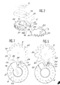
- - La Figure 1 est une vue partielle de dessus d'un mécanisme de serrure selon l'invention, illustrant plus particulièrement le profil des deux pignons assurant la transmission du mouvement du panneton d'un barillet vers le fouillot d'actionnement d'une tringle coulissante.
- - La Figure 2 est une vue en perspective, précisant le profil des premier et second pignons mis en oeuvre dans le mécanisme de la figure 1.
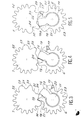
- - Les Figures 3 à 7 sont des vues plus schématiques des deux pignons de la transmission, permettant d'expliciter le fonctionnement de celle-ci au cours des différentes phases successives, de la rotation du panneton.
- - Figure 1 is a partial top view of a lock mechanism according to the invention, more particularly illustrating the profile of the two pinions ensuring the transmission of the movement of the bit from a barrel to the actuating rod of a rod sliding.
- - Figure 2 is a perspective view, specifying the profile of the first and second pinions used in the mechanism of Figure 1.
- - Figures 3 to 7 are more schematic views of the two gears of the transmission, to explain the operation of the latter during the various successive phases of the rotation of the bit.
Sur la Figure 1, la référence 1 désigne le coffre, représenté ouvert, d'une serrure à barillet selon l'invention. Celle-ci comporte, très schématiquement illustré sur le dessin, un tringle coulissante 2 dont le déplacement permet l'actionnement transversal en saillie ou en retrait dans le coffre 1 d'éléments de verrouillage (non représentés), la serrure étant elle-même montée dans l'épaisseur du dormant ou du battant d'une porte ou analogue.In Figure 1, the
La tringle coulissante 2 est elle-même actionnée par un fouillot à crémaillère 3, dont le mouvement est obtenu par engrènement de celui-ci avec un pignon 4, fixé sur un axe 5 perpendiculaire au plan de la Figure 1. La rotation dans un sens ou dans l'autre du pignon d'entraînement 4 est réalisé grâce à un jeu de deux autres pignons de commande, respectivement un premier pignon 6 et un second pignon 7, engrenant mutuellement l'un avec l'autre.The
Le premier pignon 6 est monté dans un évidement circulaire d'un support 8, prolongé à sa partie inférieure par un logement allongé 9. Ce pignon 6 comporte par ailleurs une partie centrale évidée 10, permettant l'engagement axial dans ce pignon d'un corps de barillet 11 dont la partie inférieure 12 pénètre dans le logement 9, en étant ainsi guidée par ce dernier. Le support 8 du pignon 6 est immobilisé dans le coffre 1 de la serrure et présente à cet effet un passage transversal 13 pour le montage d'une vis de blocage 14 qui traverse également la partie inférieure 12 du barillet. Le démontage de la vis 14 permet ainsi, à la demande, de changer le corps de barillet 11 pour le remplacer par un autre en cas de défectuosité ou plus généralement pour substituer au barillet initial un autre de même profil mais adapté à une clé différente, en particulier lorsque l'utilisateur a perdu la première.The
De façon classique, le corps du barillet 11 comporte un panneton 15, monté mobile autour de l'axe du corps sous l'effet d'une clé 16 engagée dans ce dernier. Le profil de la clé, de même que l'agencement des pièces intérieures du barillet, notamment des goupilles de celui-ci, n'autorisant la rotation du panneton 15 que pour un profil déterminé et précis de cette clé une fois introduite dans le corps 11, ne sont pas décrits ici, ces dispositions étant en elles-mêmes classiques et bien connues dans la technique.Conventionally, the body of the
Le premier pignon 6 comporte deux dents d'actionnement, respectivement 17 et 18, formant surépaisseurs sur le dessus du pignon et séparées l'une de l'autre par une fente 19 dans lequel s'introduit avec jeu le panneton 15 du barillet lorsque celui-ci est monté dans la partie centrale évidée 10 du pignon. Les dents 17 et 18 sont ainsi disposées de part et d'autre du panneton 15 qui, en quelque sorte, joue le rôle, dans le pignon 6, d'une large dent complémentaire, en fait manquante dans l'espace 19.The
Comme on le voit également sur la figure 2, des dents 17 et 18 présentent à l'opposé de la fente 19, des logements 17a et 18a respectivement, fermés du côté de cette fente mais ouverts vers l'extérieur.As can also be seen in FIG. 2,
Le pignon 6 comporte par ailleurs, au-delà des logements 17a et 18a, deux crans respectivement 20 et 21 dont le profil est déterminé d'une façon qui sera précisée plus loin. Au-delà de ces crans, le pignon comporte enfin une série de dents 22 pour l'entraînement de dents homologues 23 du second pignon 7. Les dents 22 et 23 présentant un profil approprié mais une largeur maximale très sensiblement inférieure à celle des dents d'actionnement 17 et 18 d'une part et des crans 20 et 21 d'autre part.The
Le second pignon 7 est monté sur l'axe 5 portant le pignon 4 de telle sorte qu'à partir du mouvement qu'il reçoit du premier pignon 6, il transmette à son tour une rotation correspondante au pignon 4 et par celui-ci, au fouillot 3.The
Dans la situation des pignons 6 et 7 illustrée sur la Figure 1, les dents d'actionnement 17 et 18 du premier pignon 6 sont dans une position symétrique par rapport au logement 9 dans lequel s'engage la partie inférieure 12 du corps de barillet 11, le panneton 15 étant également à l'intérieur de ce logement. Dans cette position, le second pignon 7 est agencé de telle sorte qu'il présente respectivement, à l'opposé des éléments constituant le premier pignon, des logements, des parties homologues, mais néanmoins non identiques, aménagées pour coopérer avec les premiers au cours de la rotation mutuelle en sens inverse des deux pignons. Le pignon 7 comporte ainsi, d'abord deux dents réceptrices 24 et 25, propres à s'engager successivement et respectivement dans les logements 17a et 18a du premier pignon. Ces dents réceptrices 24 et 25 sont séparées l'une de l'autre, sur la périphérie du pignon 7, par un espace libre 26 dont le profil et notamment la largeur sont sensiblement identiques à ceux de la fente 19 du premier pignon 6. A l'opposé de cet espace 26, de chaque côté des dents réceptrices 24 et 25, le pignon 7 comporte deux parties en creux 27 et 28, destinées à recevoir, en position adéquate des deux pignons, l'une ou l'autre des dents d'actionnement 17 et 18. Enfin, le pignon 7 comprend au-delà des parties en creux 27 et 28, deux extensions complémentaires 29 et 30, celles-ci présentant un profil arrondi à courbure convexe et continue, correspondant aux creux des crans 20 et 21 du premier pignon 6.In the situation of the
Selon l'invention, les dents réceptrices 24 et 25 d'une part, les extensions complémentaires 29 et 30 d'autre part du second pignon 7, sont réalisées dans le plan de celui-ci, comme l'illustre la vue en perspective de la Figure 2, le pignon 4 pouvant dès lors être monté sur le dessus de ce pignon 7, de telle façon que l'épaisseur de l'ensemble ne soit en réalité que l'addition des épaisseurs relatives de ces pignons 4 et 7et ne dépasse pas celle du pignon 6, notamment au droit des dents d'actionnement 17 et 18 de celui-ci. Le premier pignon 6 présente une au droit de ces dernières une épaisseur approximativement double et au total pratiquement égale à celle des pignons 4 et 7 ainsi superposés.According to the invention, the
Les Figures 3 à 7 permettent alors d'expliciter le fonctionnement de la serrure perfectionnée selon l'invention.Figures 3 to 7 then explain the operation of the improved lock according to the invention.
Dans la position initiale représentée sur la Figure 1, la clé 16 est introduite dans le barillet 11 puis entraîne le panneton 15 de celui-ci dans le sens, par exemple, contraire à celui des aiguilles d'une montre. Le panneton 15 vient ainsi au contact du flan latéral de la dent d'actionnement 17 et fait tourner sur lui-même le premier pignon 6. Celui-ci, par ses dents 22, engrène avec les dents 23 du second pignon 7 et transmet ainsi le mouvement de la clé au pignon 4 et, de celui-ci, au fouillot 3.In the initial position shown in Figure 1, the
Dans la position représentée sur la Figure 3, la dent réceptrice 25 du second pignon 7 est venue s' engager dans le logement 18a ménagé dans la dent d'actionnement 17, de telle sorte que la poursuite de la rotation relative des deux pignons puisse se produire sans solution de continuité sous l'effet du panneton 15 qui pénètre progressivement dans l'espace 26 séparant les dents 24 et 25. Cette rotation se poursuit jusqu'à ce que la dent réceptrice 24 vienne à son tour coopérer avec le flan intérieur de la dent d'actionnement 18 dans le logement 18a de cette dernière, le mouvement se continuant tandis que l'extension complémentaire 27 s'engage progressivement dans le cran 20 en évitant que la dent 24 n'échappe à la dent 18 en raison du jeu laissé libre pour le panneton dans la fente 19. En finale, les dents 22 du pignon 6 reprennent leur engrènement avec les dents 23 du second pignon 7, le mécanisme ayant accompli un tour complet.In the position shown in Figure 3, the receiving
On réalise ainsi une continuité permanente du mouvement d'entraînement du second pignon 7 par le premier 6, les dents successives de l'un et de l'autre coopérant mutuellement sans interruption, même au droit de la fente 19 et au jeu laissé libre dans celle-ci. En revanche, en cas de rupture des goupilles du barillet, en particulier lorsque celui-ci est forcé, les dispositions prévues sont telles qu'un effort en sens inverse exercé sur la tringle coulisante 2 et, à partir de celle-ci sur le fouillot 3 et le pignon 4, ne puisse pas provoquer la rotation des pignons 1 et 2 et le déverrouillage de la porte.This produces a permanent continuity of the drive movement of the
Dans ce cas en effet, la différence de largeur entre la fente 19 séparant les dents d'actionnement 17 et 18 du premier pignon et le panneton 15, autorise immédiatement un léger décalage du second pignon 7 par rapport au premier 6, tel que, en cas d'effort exercé sur ce second pignon pour le faire alors tourner dans le sens des aiguilles d'une montre, le premier pignon 6 soit instantanément bloqué dans sa rotation par la dent réceptrice 25 qui ne peut plus s'engager dans le logement 17a de la dent 17 mais bute latéralement contre le flan de celle-ci.In this case, in fact, the difference in width between the
Le mécanisme selon l'invention permet donc, en convenant tous les avantages de la solution classique notamment vis à vis de la sécurité de son fonctionnement en cas d'effort exercé sur la tringle coulissante introduisant le déverrouillage de la serrure, de réaliser cette dernière avec une épaisseur notablement réduite, autorisant son montage dans des supports étroits, blindés ou non. Il en résulte une économie de place appréciable, permettant d'envisager le montage de serrures de sécurité notamment à cinq points de fermeture dans des portes dont l'épaisseur ne permet pas normalement un tel montage avec des serrures classiques trop épaisses.The mechanism according to the invention therefore makes it possible, by agreeing to all the advantages of the conventional solution, in particular with regard to the safety of its operation in the event of a force exerted on the sliding rod introducing the unlocking of the lock, to carry out the latter with a significantly reduced thickness, allowing it to be mounted in narrow supports, shielded or not. This results in a significant saving of space, making it possible to envisage the mounting of security locks, in particular with five closing points in doors whose thickness does not normally allow such mounting with conventional locks that are too thick.
Bien entendu, il va de soi que l'invention ne se limite pas à l'exemple de réalisation décrit ci-dessus donné simplement à titre indicatif ; elle en embrasse au contraire toutes les variantes.Of course, it goes without saying that the invention is not limited to the embodiment described above given simply for information; on the contrary, it embraces all its variants.
Claims (3)
Applications Claiming Priority (2)
| Application Number | Priority Date | Filing Date | Title |
|---|---|---|---|
| FR8616376 | 1986-11-25 | ||
| FR8616376A FR2607176B1 (en) | 1986-11-25 | 1986-11-25 | LOCK WHICH THE BARREL IS COUPLED, BY A SET OF PINIONS, WITH THE PIECE DRIVING THE PENEER |
Publications (3)
| Publication Number | Publication Date |
|---|---|
| EP0270425A2 true EP0270425A2 (en) | 1988-06-08 |
| EP0270425A3 EP0270425A3 (en) | 1988-07-06 |
| EP0270425B1 EP0270425B1 (en) | 1990-06-20 |
Family
ID=9341168
Family Applications (1)
| Application Number | Title | Priority Date | Filing Date |
|---|---|---|---|
| EP19870402536 Expired - Lifetime EP0270425B1 (en) | 1986-11-25 | 1987-11-10 | Lock with a rotor connected to the bolt by a set of pinions |
Country Status (4)
| Country | Link |
|---|---|
| EP (1) | EP0270425B1 (en) |
| DE (1) | DE3763325D1 (en) |
| ES (1) | ES2016858B3 (en) |
| FR (1) | FR2607176B1 (en) |
Cited By (9)
| Publication number | Priority date | Publication date | Assignee | Title |
|---|---|---|---|---|
| FR2690944A1 (en) * | 1992-05-05 | 1993-11-12 | Brogser Sa | Barrel lock - has two meshing gears equipped with interacting radial catch and projections |
| GB2272247A (en) * | 1992-11-05 | 1994-05-11 | Gary Christian | Axial push and pull locking device |
| GB2274306A (en) * | 1993-01-13 | 1994-07-20 | Parys Remi E Van | Lock mechanism |
| FR2707322A1 (en) * | 1993-07-05 | 1995-01-13 | Laperche Sa | Lock with a cylinder and with gears for transmitting the movement to the lock bolt |
| FR2708305A1 (en) * | 1993-06-30 | 1995-02-03 | Laperche Sa | Geared lock having an improved cylinder |
| WO1998045558A1 (en) * | 1997-04-08 | 1998-10-15 | Lockwood Australia Pty. Ltd. | Lock mechanism |
| EP0906996A2 (en) | 1997-10-03 | 1999-04-07 | C.I.S.A. Costruzioni Italiane Serrature Affini S.p.A. | Lock provided with a gear device for actuating at least one bolt |
| ITNO20100002A1 (en) * | 2010-05-05 | 2011-11-06 | Mimosa Arso | SAFETY LOCK FOR UP-AND-OVER DOORS |
| FR3008123A1 (en) * | 2013-07-02 | 2015-01-09 | Tordjman | LOCK CYLINDER, LOCK EQUIPPED WITH SUCH A CYLINDER |
Families Citing this family (2)
| Publication number | Priority date | Publication date | Assignee | Title |
|---|---|---|---|---|
| DE9104553U1 (en) * | 1991-04-13 | 1991-06-06 | Bks Gmbh, 5620 Velbert, De | |
| DE19650136B4 (en) * | 1996-12-03 | 2006-06-29 | Brose Schließsysteme GmbH & Co.KG | Motor vehicle door lock o. The like. With freewheel |
Citations (1)
| Publication number | Priority date | Publication date | Assignee | Title |
|---|---|---|---|---|
| EP0041217A1 (en) * | 1980-06-04 | 1981-12-09 | Gretsch-Unitas GmbH Baubeschlagfabrik | Drive for at least one bolt |
-
1986
- 1986-11-25 FR FR8616376A patent/FR2607176B1/en not_active Expired
-
1987
- 1987-11-10 DE DE8787402536T patent/DE3763325D1/en not_active Expired - Lifetime
- 1987-11-10 EP EP19870402536 patent/EP0270425B1/en not_active Expired - Lifetime
- 1987-11-10 ES ES87402536T patent/ES2016858B3/en not_active Expired - Lifetime
Patent Citations (1)
| Publication number | Priority date | Publication date | Assignee | Title |
|---|---|---|---|---|
| EP0041217A1 (en) * | 1980-06-04 | 1981-12-09 | Gretsch-Unitas GmbH Baubeschlagfabrik | Drive for at least one bolt |
Cited By (18)
| Publication number | Priority date | Publication date | Assignee | Title |
|---|---|---|---|---|
| FR2690944A1 (en) * | 1992-05-05 | 1993-11-12 | Brogser Sa | Barrel lock - has two meshing gears equipped with interacting radial catch and projections |
| GB2272247A (en) * | 1992-11-05 | 1994-05-11 | Gary Christian | Axial push and pull locking device |
| DE4400473C2 (en) * | 1993-01-13 | 2003-11-20 | Parys Remi E Van | Lock mechanism and lock provided with such a lock mechanism |
| GB2274306A (en) * | 1993-01-13 | 1994-07-20 | Parys Remi E Van | Lock mechanism |
| FR2704264A1 (en) * | 1993-01-13 | 1994-10-28 | Parys Remi E Van | Lock mechanism and closure provided with such a lock mechanism. |
| GB2274306B (en) * | 1993-01-13 | 1995-10-11 | Parys Remi E Van | Lock mechanism,and a locking device incorporating such a lock mechanism |
| BE1008364A5 (en) * | 1993-01-13 | 1996-04-02 | Parys Remi E Van | Lock mechanism and closure with such lock mechanism. |
| FR2708305A1 (en) * | 1993-06-30 | 1995-02-03 | Laperche Sa | Geared lock having an improved cylinder |
| FR2707322A1 (en) * | 1993-07-05 | 1995-01-13 | Laperche Sa | Lock with a cylinder and with gears for transmitting the movement to the lock bolt |
| WO1998045558A1 (en) * | 1997-04-08 | 1998-10-15 | Lockwood Australia Pty. Ltd. | Lock mechanism |
| GB2338264A (en) * | 1997-04-08 | 1999-12-15 | Lockwood Australia Pty Ltd | Lock mechanism |
| AU719921B2 (en) * | 1997-04-08 | 2000-05-18 | Lockwood Security Products Pty Limited | Lock mechanism |
| GB2338264B (en) * | 1997-04-08 | 2001-06-13 | Lockwood Australia Pty Ltd | Lock mechanism |
| US6374650B1 (en) | 1997-04-08 | 2002-04-23 | Lockwood Australia Pty Ltd. | Lock mechanism |
| EP0906996A3 (en) * | 1997-10-03 | 2001-06-13 | CISA S.p.A. | Lock provided with a gear device for actuating at least one bolt |
| EP0906996A2 (en) | 1997-10-03 | 1999-04-07 | C.I.S.A. Costruzioni Italiane Serrature Affini S.p.A. | Lock provided with a gear device for actuating at least one bolt |
| ITNO20100002A1 (en) * | 2010-05-05 | 2011-11-06 | Mimosa Arso | SAFETY LOCK FOR UP-AND-OVER DOORS |
| FR3008123A1 (en) * | 2013-07-02 | 2015-01-09 | Tordjman | LOCK CYLINDER, LOCK EQUIPPED WITH SUCH A CYLINDER |
Also Published As
| Publication number | Publication date |
|---|---|
| FR2607176A1 (en) | 1988-05-27 |
| FR2607176B1 (en) | 1989-03-31 |
| DE3763325D1 (en) | 1990-07-26 |
| EP0270425B1 (en) | 1990-06-20 |
| EP0270425A3 (en) | 1988-07-06 |
| ES2016858B3 (en) | 1990-12-01 |
Similar Documents
| Publication | Publication Date | Title |
|---|---|---|
| EP0270425B1 (en) | Lock with a rotor connected to the bolt by a set of pinions | |
| EP0943768B1 (en) | Return device of the actuating member for a lock housing, espagnolette lock or similar | |
| CH620014A5 (en) | ||
| EP0778595B1 (en) | Safety switch with key | |
| FR2641312A1 (en) | MECHANISM FOR TILTING DOORS | |
| EP0140740B1 (en) | Safety lock | |
| EP0645511A1 (en) | Lock for a vehicle door | |
| EP0801193A1 (en) | Mortise lock | |
| EP1681411B1 (en) | Lock cylinder for key having a key bit which cross section is non-circular | |
| EP0764565B1 (en) | Motorized vehicle steering lock | |
| EP3808925B1 (en) | Lock for a door of a motor vehicle | |
| EP0325813B1 (en) | Lock with a clutch | |
| EP0170577A1 (en) | Control device for opening a motor vehicle door lock | |
| FR2759333A1 (en) | Link mechanism for vehicle seat | |
| EP0940529A1 (en) | Double plug security cylinder | |
| EP0230808B1 (en) | Locking control mechanism for vehicle door lock | |
| EP0846603B1 (en) | Actuator, in particular for a vehicle anti-theft device | |
| EP4050182B1 (en) | Device for controlling a mechanism for locking/unlocking a door leaf | |
| FR2552146A1 (en) | Security lock | |
| FR2766441A1 (en) | Electrically operated steering column lock with locking of bolt | |
| FR2941544A3 (en) | Horizontal controllable knuckle or vertical controllable knuckle activating device for rear door of commercial vehicle, has auxiliary handle modifying configurations of internal transmission unit when knuckles are not activated | |
| EP0841449A1 (en) | Monodirectional esplagnolette | |
| EP0869236B1 (en) | Safety cylinder operable from one side even when a key is inserted in the opposite side | |
| EP1702125B1 (en) | Device for selectively blocking an actuating movement of a security lock with fittings and a moveable ratchet | |
| FR2707322A1 (en) | Lock with a cylinder and with gears for transmitting the movement to the lock bolt |
Legal Events
| Date | Code | Title | Description |
|---|---|---|---|
| PUAI | Public reference made under article 153(3) epc to a published international application that has entered the european phase |
Free format text: ORIGINAL CODE: 0009012 |
|
| PUAL | Search report despatched |
Free format text: ORIGINAL CODE: 0009013 |
|
| AK | Designated contracting states |
Kind code of ref document: A2 Designated state(s): BE DE ES GB IT |
|
| AK | Designated contracting states |
Kind code of ref document: A3 Designated state(s): BE DE ES GB IT |
|
| 17P | Request for examination filed |
Effective date: 19881215 |
|
| 17Q | First examination report despatched |
Effective date: 19891123 |
|
| ITF | It: translation for a ep patent filed |
Owner name: CALVANI SALVI E VERONELLI S.R.L. |
|
| GRAA | (expected) grant |
Free format text: ORIGINAL CODE: 0009210 |
|
| AK | Designated contracting states |
Kind code of ref document: B1 Designated state(s): BE DE ES GB IT |
|
| GBT | Gb: translation of ep patent filed (gb section 77(6)(a)/1977) | ||
| REF | Corresponds to: |
Ref document number: 3763325 Country of ref document: DE Date of ref document: 19900726 |
|
| PLBE | No opposition filed within time limit |
Free format text: ORIGINAL CODE: 0009261 |
|
| STAA | Information on the status of an ep patent application or granted ep patent |
Free format text: STATUS: NO OPPOSITION FILED WITHIN TIME LIMIT |
|
| 26N | No opposition filed | ||
| ITTA | It: last paid annual fee | ||
| PGFP | Annual fee paid to national office [announced via postgrant information from national office to epo] |
Ref country code: GB Payment date: 19971110 Year of fee payment: 11 |
|
| PGFP | Annual fee paid to national office [announced via postgrant information from national office to epo] |
Ref country code: ES Payment date: 19971128 Year of fee payment: 11 |
|
| PG25 | Lapsed in a contracting state [announced via postgrant information from national office to epo] |
Ref country code: GB Free format text: LAPSE BECAUSE OF NON-PAYMENT OF DUE FEES Effective date: 19981110 |
|
| PG25 | Lapsed in a contracting state [announced via postgrant information from national office to epo] |
Ref country code: ES Free format text: LAPSE BECAUSE OF EXPIRATION OF PROTECTION Effective date: 19981111 |
|
| GBPC | Gb: european patent ceased through non-payment of renewal fee |
Effective date: 19981110 |
|
| REG | Reference to a national code |
Ref country code: ES Ref legal event code: FD2A Effective date: 20010201 |
|
| PG25 | Lapsed in a contracting state [announced via postgrant information from national office to epo] |
Ref country code: IT Free format text: LAPSE BECAUSE OF NON-PAYMENT OF DUE FEES Effective date: 20051110 |
|
| PGFP | Annual fee paid to national office [announced via postgrant information from national office to epo] |
Ref country code: DE Payment date: 20061019 Year of fee payment: 20 |
|
| PGFP | Annual fee paid to national office [announced via postgrant information from national office to epo] |
Ref country code: BE Payment date: 20061030 Year of fee payment: 20 |
|
| BE20 | Be: patent expired |
Owner name: *STREMLER Effective date: 20071110 |