EP0268845B1 - Membrankondensator zur Messung sehr geringer pneumatischer Wechseldrücke - Google Patents
Membrankondensator zur Messung sehr geringer pneumatischer Wechseldrücke Download PDFInfo
- Publication number
- EP0268845B1 EP0268845B1 EP87115653A EP87115653A EP0268845B1 EP 0268845 B1 EP0268845 B1 EP 0268845B1 EP 87115653 A EP87115653 A EP 87115653A EP 87115653 A EP87115653 A EP 87115653A EP 0268845 B1 EP0268845 B1 EP 0268845B1
- Authority
- EP
- European Patent Office
- Prior art keywords
- base plate
- membrane
- ceramics base
- annular mandrel
- fixed electrode
- Prior art date
- Legal status (The legal status is an assumption and is not a legal conclusion. Google has not performed a legal analysis and makes no representation as to the accuracy of the status listed.)
- Expired - Lifetime
Links
- 239000012528 membrane Substances 0.000 claims description 32
- 239000000919 ceramic Substances 0.000 claims description 21
- 239000002184 metal Substances 0.000 claims description 21
- 229910052751 metal Inorganic materials 0.000 claims description 21
- 239000003990 capacitor Substances 0.000 claims description 15
- 238000005516 engineering process Methods 0.000 claims description 5
- 239000000463 material Substances 0.000 claims description 4
- 238000000034 method Methods 0.000 claims description 3
- 238000004868 gas analysis Methods 0.000 claims description 2
- 239000010409 thin film Substances 0.000 claims description 2
- 239000011248 coating agent Substances 0.000 claims 2
- 238000000576 coating method Methods 0.000 claims 2
- 238000001311 chemical methods and process Methods 0.000 claims 1
- 238000007747 plating Methods 0.000 claims 1
- 239000007789 gas Substances 0.000 description 3
- 239000010408 film Substances 0.000 description 2
- 238000004519 manufacturing process Methods 0.000 description 2
- 239000004020 conductor Substances 0.000 description 1
- 239000011521 glass Substances 0.000 description 1
- 150000002739 metals Chemical class 0.000 description 1
- 239000000126 substance Substances 0.000 description 1
Images
Classifications
-
- G—PHYSICS
- G01—MEASURING; TESTING
- G01L—MEASURING FORCE, STRESS, TORQUE, WORK, MECHANICAL POWER, MECHANICAL EFFICIENCY, OR FLUID PRESSURE
- G01L9/00—Measuring steady of quasi-steady pressure of fluid or fluent solid material by electric or magnetic pressure-sensitive elements; Transmitting or indicating the displacement of mechanical pressure-sensitive elements, used to measure the steady or quasi-steady pressure of a fluid or fluent solid material, by electric or magnetic means
- G01L9/0041—Transmitting or indicating the displacement of flexible diaphragms
- G01L9/0072—Transmitting or indicating the displacement of flexible diaphragms using variations in capacitance
Definitions
- the invention relates to a membrane capacitor for measuring very low pneumatic alternating pressures, in particular in gas analysis devices with optopneumatic detectors according to the preamble of claim 1.
- Such a membrane capacitor is known from DE-GM 79 22 944.
- This membrane capacitor has a fixed electrode made of metal and an annular mandrel with a foot part arranged around it at a distance.
- the fixed electrode and the base part of the annular mandrel are attached to a ceramic plate.
- the membrane of the capacitor is fixed in a socket which consists of two ring-shaped parts, a flat ring and another ring, the cross-sectional area of which is of rectangular shape.
- the ring-shaped holder part has an internal fine thread with which the holder is screwed onto the mandrel provided with a corresponding counter thread.
- the membrane is tensioned by twisting the socket for the membrane relative to the annular mandrel.
- the height of the annular mandrel relative to the fixed electrode determines the distance between the membrane and the fixed electrode.
- Such membrane capacitors are very expensive to manufacture. There are also large gas-wetted metal surfaces that require chemically resistant metals in the case of aggressive gases
- the invention has for its object to provide a membrane capacitor of the type mentioned, which is easier to manufacture and in which the gas-contacted metal surfaces are reduced to a minimum.
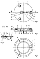
- the ceramic base plate 1 has a concentrically arranged cylindrical elevation 1a.
- an annular mandrel 2 is applied by material application.
- a circular metal layer serving as a fixed electrode 3 is applied to the cylindrical elevation 1a of the ceramic plate 1.
- a metal membrane 4 is held in a manner known per se between two rings 5, 6, which form a clamping ring arrangement.
- the metal membrane 4 lies on the annular mandrel 2.
- Screws 7, 8, 9 connect the clamping ring arrangement to the ceramic base plate 1.
- the tension of the metal membrane 4 can be adjusted using the screws 7, 8, 9.
- a plate spring 10 which is provided with holes according to the arrangement of the screws 7, 8, 9 serves to secure the screws against unintentional loosening and absorbs the forces generated by the weight of the rings 5, 6.
- the ceramic base plate 1 has an opening 1b, the wall surface of which is provided with a metal layer 11. The opening 1b establishes the gas connection to the interior of the membrane capacitor.
- the fixed electrode 3 is electrically connected to a first contact tap 12 via the metal layer 11.
- the electrical connection of the metal membrane 4 to a further contact tap 14 takes place via the electrically conductive rings 5, 6 as well as via the screw 7 and a conductor track 13.
- FIG. 3 shows a detail of FIG. 2 in an enlarged view.
- the annular mandrel 2 consists of two layers 2a and 2b which are applied in the outer region of the cylindrical elevation 1a of the ceramic base plate 1.
- the layers 2a and 2b are printed on the ceramic base plate 1 in a manner known per se from glass or another material using thick-film technology.
- the lower layer 2a is designed as a wide ring, while the top layer 2b is designed as a narrow ring with a spherical surface in the outer region of the lower layer 2a.
- the total height of the annular mandrel 2 determines the distance between the fixed electrode 3 and the metal membrane 4 of the membrane capacitor and is in the order of 40 to 150 ⁇ m depending on the application.
- the lower layer 2a can also be applied in several work steps, ie in several layers.
- the arrangement of the uppermost layer 2b in the outer region of the underlying layer prevents the metal membrane 4 from being clamped on the outer edge of the cylindrical elevation 1a the ceramic base plate 1 comes to rest.
- the spherical surface of the uppermost layer 2b facilitates tensioning of the metal membrane 4 and improves the seal between the annular mandrel 2 and the metal membrane 4.
- FIG. 4 shows a top view of the membrane capacitor described above with reference to FIGS. 1 to 3.
- the metal membrane 4 and the upper ring 5 clamping ring arrangement cover most of the ceramic base plate 1.
- the surface of the cylindrical elevation 1a has a planicity of less than 3 ⁇ m over the entire cross section.
- the fixed electrode 3 consists of a metal resistant to aggressive gases, the z. B. is applied in thin film technology. Although other known processes, such as thick-film technology or chemical or galvanic processes, can also be used for this.
- the thickness of the fixed electrode 3 is less than 3 microns.
- the outer diameter of the annular mandrel 2 is between 10 and 20 mm.
Landscapes
- Physics & Mathematics (AREA)
- General Physics & Mathematics (AREA)
- Measuring Fluid Pressure (AREA)
- Investigating Or Analyzing Materials By The Use Of Electric Means (AREA)
- Fixed Capacitors And Capacitor Manufacturing Machines (AREA)
Description
- Die Erfindung bezieht sich auf einen Membrankondensator zur Messung sehr geringer pneumatischer Wechseldrücke, insbesondere in Gasanalysengeräten mit optopneumatischen Detektoren gemäß dem Oberbegriff des Anspruchs 1.
- Ein derartiger Membrankondensator ist aus dem DE-GM 79 22 944 bekannt. Dieser Membrankondensator weist eine Festelektrode aus Metall und einen um diese mit Abstand angeordneten ringförmigen Dorn mit einem Fußteil auf. Die Festelektrode und der Fußteil des ringförmigen Dorns sind auf einer Keramikplatte befestigt. Die Membran des Kondensators ist in einer Fassung befestigt, die aus zwei ringförmigen Teilen besteht, einem flachen Ring und einem weiteren Ring, dessen Querschnittsfläche von rechtwinkliger Gestalt ist. Der ringförmige Fassungsteil besitzt ein Innenfeingewinde, mit dem die Fassung auf den mit einem entsprechenden Gegengewinde versehenen Dorn aufgeschraubt ist. Die Spannung der Membran erfolgt durch Verdrehen der Fassung für die Membran gegenüber dem ringförmigen Dorn. Die Höhe des ringförmigen Dornes gegenüber der Festelektrode bestimmt den Abstand zwischen Membran und Festelektrode. Derartige Membrankondensatoren sind sehr aufwendig in der Fertigung. Außerdem existieren große gasberührte Metallfächen, die bei aggressiven Gasen chemisch beständige Metalle erfordern.
- Der Erfindung liegt die Aufgabe zugrunde, einen Membrankondensator der eingangs genannten Art zu schaffen, der einfacher zu fertigen ist und bei dem die gasberührten Metallflächen auf ein Minimum reduziert sind.
- Diese Aufgabe wird erfindungsgemäß durch die im kennzeichnenden Teil des Anspruchs 1 angegebenen Merkmale gelöst.
- Die Erfindung wird durch die Merkmale der Unteransprüche weitergebildet.
- Die Erfindung wird im folgenden mit ihren weiteren Einzelheiten anhand eines in den Zeichnungen dargestellten Ausführungsbeispiels näher erläutert. Die Zeichnungen zeigen verschiedene Ansichten eines Membrankondensators nach der Erfindung, und zwar
- Figur 1 eine Ansicht der Unterseite,
- Figur 2 einen Schnitt entlang der Linie A - B in der Figur 1,
- Figur 3 ein Detail der Figur 2 in vergrößerter Darstellung und
- Figur 4 eine Draufsicht.
- Eine kreisförmige Keramikgrundplatte 1, deren Unterseite in der Figur 1 dargestellt ist, ist in der Figur 2 geschnitten dargestellt. Die Keramikgrundplatte 1 weist eine konzentrisch angeordnete zylinderförmige Erhebung 1a auf. Auf dem Außenbereich der zylinderförmigen Erhebung 1a der Keramikgrundplatte 1 ist durch Materialauftrag ein ringförmiger Dorn 2 aufgebracht. Innerhalb des ringförmigen Dorns 2 ist auf der zylinderförmigen Erhebung 1a der Keramikplatte 1 eine als Festelektrode 3 dienende kreisförmige Metallschicht aufgebracht. Eine Metallmembran 4 ist in an sich bekannter Weise zwischen zwei Ringen 5, 6, die eine Spannringanordnung bilden, gehalten. Die Metallmembran 4 liegt auf dem ringförmigen Dorn 2 auf. Drei gleichmäßig über den Umfang der aus den Ringen 5, 6 gebildeten Spannringanordnung verteilte Schrauben 7, 8, 9 verbinden die Spannringanordnung mit der Keramikgrundplatte 1. Die Spannung der Metallmembran 4 ist über die Schrauben 7, 8, 9 einstellbar. Eine Tellerfeder 10 die entsprechend der Anordnung der Schrauben 7, 8, 9 mit Löchern versehen ist, dient dabei zur Sicherung der Schrauben gegen ein unbeabsichtiges Lösen und nimmt die durch das Gewicht der Ringe 5, 6 entstehenden Kräfte auf. Die Keramikgrundplatte 1 weist eine Öffnung 1b auf, deren Wandfläche mit einer Metallschicht 11 versehen ist. Die Öffnung 1b stellt die Gasverbindung zu dem Innenraum des Membrankondensators her. Die Festelektrode 3 ist über die Metallschicht 11 mit einem ersten Kontaktabgriff 12 elektrisch verbunden. Die elektrische Verbindung der Metallmembran 4 mit einem weiteren Kontaktabgriff 14 erfolgt über die elektrisch leitenden Ringe 5, 6 sowie über die Schraube 7 und eine Leiterbahn 13.
- Die Figur 3 zeigt ein Detail der Figur 2 in vergrößerter Darstellung. Der ringförmige Dorn 2 besteht aus zwei Schichten 2a und 2b, die im Außenbereich der zylinderförmigen Erhebung 1a der Keramikgrundplatte 1 aufgebracht sind. Die Schichten 2a und 2b sind in an sich bekannter Weise aus Glas oder einem anderen Material in Dickschichttechnik auf die Keramikgrundplatte 1 gedruckt. Die untere Schicht 2a ist als breiter Ring ausgebildet, während die oberste Schicht 2b als schmaler Ring mit balliger Oberfläche im Außenbereich der unteren Schicht 2a ausgebildet ist. Die Gesamthöhe des ringförmigen Dorns 2 bestimmt den Abstand zwischen der Festelektrode 3 und der Metallmembran 4 des Membrankondensators und liegt je nach Anwendungszweck in der Größenordnung von 40 bis 150 mym. Bei Bedarf kann die untere Schicht 2a auch in mehreren Arbeitsgängen, d. h. in mehreren Schichten, aufgebracht werden. Wie insbesondere die Figur 3 zeigt, verhindert die Anordnung der obersten Schicht 2b im Außenbereich der darunterliegenden Schicht, daß die Metallmembran 4 beim Spannen auf der Außenkante der zylinderförmigen Erhebung 1a der Keramikgrundplatte 1 zur Auflage kommt. Die ballige Oberfläche der obersten Schicht 2b erleichtert das Spannen der Metallmembran 4 und verbessert die Abdichtung zwischen dem ringförmigen Dorn 2 und der Metallmembran 4.
- Die Figur 4 zeigt eine Draufsicht auf den oben anhand der Figuren 1 bis 3 beschriebenen Membrankondensator. Die Metallmembran 4 und der obere Ring 5 Spannringanordnung verdecken den größten Teil der Keramikgrundplatte 1.
- Die Oberfläche der zylinderförmigen Erhebung 1a besitzt eine Planizität von kleiner 3 mym über den gesamten Querschnitt. Die Festelektrode 3 besteht aus einem gegen aggressive Gase beständigem Metall, das z. B. in Dünnschichttechnik aufgebracht ist. Obwohl auch andere bekannte Verfahren, wie Dickschichttechnik oder chemische oder galvanische Verfahren, hierzu verwendet werden können. Die Dicke der Festelektrode 3 ist kleiner als 3 mym. Der Außendurchmesser des ringförmigen Dorns 2 liegt zwischen 10 und 20 mm.
Claims (3)
- Membrankondensator zur Messung sehr geringer pneumatischer Wechseldrücke, insbesondere in Gasanalysengeräten mit optopneumatischen Detektoren, mit einer Keramikgrundplatte, die einen ringförmigen Dorn trägt, über den eine in einer Spannringanordnung gehaltene Metallmembran gespannt ist, die die eine Elektrode des Membrankondensators bildet, und mit einer innerhalb des ringförmigen Dorns angeordneten Festelektrode, die mit der Keramikgrundplatte verbunden ist und die andere Elektrode des Membrankondensators bildet, dadurch gekennzeichnet,- daß die Keramikgrundplatte (1) eine zylinderförmige Erhebung (1a) aufweist, die in ihrem Außenbereich den ringförmigen Dorn (2) und in ihrem Innenbereich die Festelektrode (3) trägt,- daß der ringförmige Dorn (2) durch Materialauftrag auf die Keramikgrundplatte (1) gebildet ist, wobei der ringförmige Dorn (2) aus mindestens zwei Schichten (2a, 2b) besteht, von denen mindestens die unterste Schicht (2a) als breiter Ring ausgebildet ist und die oberste Schicht (2b) als schmaler Ring ausgebildet ist, der im Außenbereich des breiten Rings angeordnet ist,- daß die Auflagefläche des ringförmigen Dorns (2) für die Membranelektrode (4) ballig ausgebildet ist,- daß die Festelektrode (3) durch Auftrag einer Metallschicht auf die Keramikgrundplatte (1) gebildet ist,- daß die Metallmembran (4) zwischen zwei Ringen (5, 6) gehalten ist, deren Innendurchmesser größer als der Außendurchmesser des ringförmigen Dorns (2) und größer als der Außendurchmesser der zylinderförmigen Erhebung (1a) der Keramikgrundplatte (1) ist,- daß die aus den miteinander verbundenen Ringen (5, 6) gebildete Spannringanordnung durch mindestens drei über den Umfang der Spannringanordnung verteilte Schrauben (7, 8, 9) mit der Keramikgrundplatte (1) verbunden ist, wobei die Spannung der Metallmembran (4) durch Änderung des Abstands zwischen den Ringen (5, 6) der Spannringanordnung und der Keramikgrundplatte (1) einstellbar ist, und- daß eine Tellerfeder (10), deren Innendurchmesser größer als der Außendurchmesser des ringförmigen Dorns (2) ist, zwischen den Ringen (5, 6) der Spannringanordnung und der Keramikgrundplatte (1) angeordnet ist.
- Membrankondensator nach Anspruch 1, dadurch gekennzeichnet, daß die Tellerfeder (10) mit Durchgangslöchern versehen ist und daß die Schrauben (7, 8, 9) durch die Durchgangslöcher geführt sind.
- Membrankondensator nach Anspruch 1 oder Anspruch 2, dadurch gekennzeichnet, daß der Materialauftrag auf die Keramikgrundplatte (1) in Dünnfilmtechnik, in Dickschichttechnik, nach einem chemischen Verfahren und/oder nach einem galvanischen Verfahren aufgebracht ist.
Applications Claiming Priority (2)
| Application Number | Priority Date | Filing Date | Title |
|---|---|---|---|
| DE3640718 | 1986-11-28 | ||
| DE19863640718 DE3640718A1 (de) | 1986-11-28 | 1986-11-28 | Membrankondensator zur messung sehr geringer pneumatischer wechseldruecke |
Publications (3)
| Publication Number | Publication Date |
|---|---|
| EP0268845A2 EP0268845A2 (de) | 1988-06-01 |
| EP0268845A3 EP0268845A3 (en) | 1990-07-04 |
| EP0268845B1 true EP0268845B1 (de) | 1992-04-15 |
Family
ID=6315017
Family Applications (1)
| Application Number | Title | Priority Date | Filing Date |
|---|---|---|---|
| EP87115653A Expired - Lifetime EP0268845B1 (de) | 1986-11-28 | 1987-10-26 | Membrankondensator zur Messung sehr geringer pneumatischer Wechseldrücke |
Country Status (2)
| Country | Link |
|---|---|
| EP (1) | EP0268845B1 (de) |
| DE (2) | DE3640718A1 (de) |
Family Cites Families (6)
| Publication number | Priority date | Publication date | Assignee | Title |
|---|---|---|---|---|
| US2667786A (en) * | 1950-02-11 | 1954-02-02 | Cons Eng Corp | Capacitor pressure gauge |
| US2808545A (en) * | 1955-01-24 | 1957-10-01 | Walter J Hirtreiter | Pressure pick-up-differential-type acceleration-free |
| US4168517A (en) * | 1977-11-10 | 1979-09-18 | Lee Shih Y | Capacitive pressure transducer |
| DE7922944U1 (de) * | 1979-08-10 | 1979-11-22 | Hartmann & Braun Ag, 6000 Frankfurt | Membrankondensator zur messung sehr geringer pneumatischer wechseldruecke in gasanalysegeraeten |
| DE3404262A1 (de) * | 1983-03-09 | 1984-09-13 | Fuji Electric Co., Ltd., Kawasaki | Kapazitiver messfuehler |
| GB2162319B (en) * | 1984-06-06 | 1987-08-19 | Furness Controls Ltd | Pressure sensitive capacitor |
-
1986
- 1986-11-28 DE DE19863640718 patent/DE3640718A1/de active Granted
-
1987
- 1987-10-26 EP EP87115653A patent/EP0268845B1/de not_active Expired - Lifetime
- 1987-10-26 DE DE8787115653T patent/DE3778310D1/de not_active Expired - Fee Related
Also Published As
| Publication number | Publication date |
|---|---|
| DE3640718A1 (de) | 1988-06-09 |
| DE3640718C2 (de) | 1989-05-24 |
| EP0268845A3 (en) | 1990-07-04 |
| EP0268845A2 (de) | 1988-06-01 |
| DE3778310D1 (de) | 1992-05-21 |
Similar Documents
| Publication | Publication Date | Title |
|---|---|---|
| DE2709945C2 (de) | Kapazitiver Druckwandler | |
| DE3883067T2 (de) | Kapazitives Manometer zur Absolutdruckmessung. | |
| DE69907423T2 (de) | Druckdifferenzwandler | |
| EP1384980A1 (de) | Feuchtigkeitsschutz für einen elektromechanischen Wandler | |
| EP1560011B1 (de) | Dehnmessstreifen mit Feuchtigkeitsschutz durch inhomogene anorganische Schicht auf glättender Polymerschicht (ORMOCER) und Schlitzanordnung | |
| EP0674164B1 (de) | Kapazitiver Drucksensor bzw. kapazitiver Differenzdrucksensor | |
| WO2001042776A1 (de) | Kapazitiver sensor | |
| DE2411212A1 (de) | Druckmesseinrichtung | |
| DE3142387A1 (de) | Kapazitiver druckfuehler | |
| DE3629628A1 (de) | Kapazitiver hochdruck-messwertumformer | |
| DE3820418A1 (de) | Differenzdruckwandler | |
| DE3313150C1 (de) | Duennschicht-Feuchtsensor zur Messung der absoluten Feuchte und Verfahren zu seiner Herstellung | |
| DE3511723C2 (de) | ||
| DE2848856A1 (de) | Kapazitiver druckwandler | |
| DE2059559B2 (de) | Elektrode mit auswechselbarer Membran zur Messung von lonenaktivitäten | |
| EP1010973B1 (de) | Kapazitive Druck- oder Differenzdruckmesszellen und Verfahren zu deren Herstellung | |
| DE69919457T2 (de) | Messtaster | |
| DE112020001474T5 (de) | Mems-gassensor-trägerkörper | |
| DE3540511C2 (de) | ||
| DE4441548A1 (de) | Neigungssensor | |
| EP0268845A2 (de) | Membrankondensator zur Messung sehr geringer pneumatischer Wechseldrücke | |
| EP0548470A1 (de) | Drucksensor mit einer Membran aus Halbleitermaterial | |
| EP0638948A1 (de) | Verfahren zur Herstellung katalytisch wirksamer Gasdiffusionselektroden | |
| EP0992778A2 (de) | Sensor und Verfahren zu seiner Herstellung | |
| DE3145584C2 (de) | Verfahren zum Durchkontaktieren einer Leiterplatte |
Legal Events
| Date | Code | Title | Description |
|---|---|---|---|
| PUAI | Public reference made under article 153(3) epc to a published international application that has entered the european phase |
Free format text: ORIGINAL CODE: 0009012 |
|
| AK | Designated contracting states |
Kind code of ref document: A2 Designated state(s): DE FR GB IT NL SE |
|
| PUAL | Search report despatched |
Free format text: ORIGINAL CODE: 0009013 |
|
| AK | Designated contracting states |
Kind code of ref document: A3 Designated state(s): DE FR GB IT NL SE |
|
| 17P | Request for examination filed |
Effective date: 19900822 |
|
| 17Q | First examination report despatched |
Effective date: 19910725 |
|
| GRAA | (expected) grant |
Free format text: ORIGINAL CODE: 0009210 |
|
| ITF | It: translation for a ep patent filed | ||
| AK | Designated contracting states |
Kind code of ref document: B1 Designated state(s): DE FR GB IT NL SE |
|
| ET | Fr: translation filed | ||
| REF | Corresponds to: |
Ref document number: 3778310 Country of ref document: DE Date of ref document: 19920521 |
|
| GBT | Gb: translation of ep patent filed (gb section 77(6)(a)/1977) | ||
| PLBE | No opposition filed within time limit |
Free format text: ORIGINAL CODE: 0009261 |
|
| STAA | Information on the status of an ep patent application or granted ep patent |
Free format text: STATUS: NO OPPOSITION FILED WITHIN TIME LIMIT |
|
| 26N | No opposition filed | ||
| PGFP | Annual fee paid to national office [announced via postgrant information from national office to epo] |
Ref country code: SE Payment date: 19940919 Year of fee payment: 8 |
|
| PGFP | Annual fee paid to national office [announced via postgrant information from national office to epo] |
Ref country code: NL Payment date: 19941031 Year of fee payment: 8 |
|
| EAL | Se: european patent in force in sweden |
Ref document number: 87115653.5 |
|
| PG25 | Lapsed in a contracting state [announced via postgrant information from national office to epo] |
Ref country code: SE Effective date: 19951027 |
|
| PG25 | Lapsed in a contracting state [announced via postgrant information from national office to epo] |
Ref country code: NL Effective date: 19960501 |
|
| EUG | Se: european patent has lapsed |
Ref document number: 87115653.5 |
|
| NLV4 | Nl: lapsed or anulled due to non-payment of the annual fee |
Effective date: 19960501 |
|
| PGFP | Annual fee paid to national office [announced via postgrant information from national office to epo] |
Ref country code: GB Payment date: 19980914 Year of fee payment: 12 |
|
| PGFP | Annual fee paid to national office [announced via postgrant information from national office to epo] |
Ref country code: FR Payment date: 19980916 Year of fee payment: 12 |
|
| PGFP | Annual fee paid to national office [announced via postgrant information from national office to epo] |
Ref country code: DE Payment date: 19980922 Year of fee payment: 12 |
|
| PG25 | Lapsed in a contracting state [announced via postgrant information from national office to epo] |
Ref country code: GB Free format text: LAPSE BECAUSE OF NON-PAYMENT OF DUE FEES Effective date: 19991026 |
|
| GBPC | Gb: european patent ceased through non-payment of renewal fee |
Effective date: 19991026 |
|
| PG25 | Lapsed in a contracting state [announced via postgrant information from national office to epo] |
Ref country code: FR Free format text: LAPSE BECAUSE OF NON-PAYMENT OF DUE FEES Effective date: 20000630 |
|
| REG | Reference to a national code |
Ref country code: FR Ref legal event code: ST |
|
| PG25 | Lapsed in a contracting state [announced via postgrant information from national office to epo] |
Ref country code: DE Free format text: LAPSE BECAUSE OF NON-PAYMENT OF DUE FEES Effective date: 20001003 |
|
| PG25 | Lapsed in a contracting state [announced via postgrant information from national office to epo] |
Ref country code: IT Free format text: LAPSE BECAUSE OF NON-PAYMENT OF DUE FEES;WARNING: LAPSES OF ITALIAN PATENTS WITH EFFECTIVE DATE BEFORE 2007 MAY HAVE OCCURRED AT ANY TIME BEFORE 2007. THE CORRECT EFFECTIVE DATE MAY BE DIFFERENT FROM THE ONE RECORDED. Effective date: 20051026 |