EP0268513B1 - Device for bus control consisting of several isolatable segments - Google Patents
Device for bus control consisting of several isolatable segments Download PDFInfo
- Publication number
- EP0268513B1 EP0268513B1 EP19870402370 EP87402370A EP0268513B1 EP 0268513 B1 EP0268513 B1 EP 0268513B1 EP 19870402370 EP19870402370 EP 19870402370 EP 87402370 A EP87402370 A EP 87402370A EP 0268513 B1 EP0268513 B1 EP 0268513B1
- Authority
- EP
- European Patent Office
- Prior art keywords
- segment
- signal
- control
- nac2
- nac1
- Prior art date
- Legal status (The legal status is an assumption and is not a legal conclusion. Google has not performed a legal analysis and makes no representation as to the accuracy of the status listed.)
- Expired - Lifetime
Links
Images
Classifications
-
- G—PHYSICS
- G06—COMPUTING; CALCULATING OR COUNTING
- G06F—ELECTRIC DIGITAL DATA PROCESSING
- G06F13/00—Interconnection of, or transfer of information or other signals between, memories, input/output devices or central processing units
- G06F13/38—Information transfer, e.g. on bus
- G06F13/40—Bus structure
- G06F13/4063—Device-to-bus coupling
- G06F13/4068—Electrical coupling
- G06F13/4072—Drivers or receivers
- G06F13/4077—Precharging or discharging
-
- G—PHYSICS
- G06—COMPUTING; CALCULATING OR COUNTING
- G06F—ELECTRIC DIGITAL DATA PROCESSING
- G06F15/00—Digital computers in general; Data processing equipment in general
- G06F15/76—Architectures of general purpose stored program computers
- G06F15/78—Architectures of general purpose stored program computers comprising a single central processing unit
- G06F15/7896—Modular architectures, e.g. assembled from a number of identical packages
Definitions
- the invention relates to a device for controlling the communication of several electrically isolable bus segments.
- Each segment being generally connected to the output terminals of circuits that can transmit or receive digital information, the communication of two or more segments then allows information to be exchanged between the circuits of one of the segments and the circuits of another. segment (see US-A-4296469 for example).
- Buses which can be subdivided into several segments find an interesting application in particular in the processing units of computers. Indeed, to be able to make several functional sub-assemblies of the unit work simultaneously and independently, it is necessary to be able to isolate the circuits of these sub-assemblies. On the other hand, we must also be able to put two functional subsets into communication with each other. As an example of subsets, we can cite operators, registers or banks of registers. To solve the previous problem, a solution consists in providing means making it possible to isolate segments of the bus at will, each segment being connected to the circuits constituting a functional sub-assembly.
- switches are used, a switch connecting two homologous lines of two adjacent segments. These switches are controlled by selection signals from the computer control unit. The logic state of the selection signals thus defines a certain configuration of the bus. Several segments can be put in series while others will be completely isolated.
- buses which can be subdivided into numerous independent segments. It must also be possible to connect two or more arbitrary segments, which can lead to a situation where the total capacity of the bus is very high. Means should then be used to maintain the voltages of the transmitted signals at a sufficient level over the entire length of the bus.
- each segment of the bus is associated with amplification means which are activated each time the segment works in transmission, in transmission or in reception.
- the invention proposes a device for controlling such a bus according to which the activation of the amplifier of any segment is subject to the activation of the amplifier of that of the adjacent segments which has already been activated.
- the subject of the invention is a bus control device constituted by several isolable segments, allowing the transfer of information from one segment to another, two adjacent segments being interconnected by switches controlled by a selection signal.
- an amplification device controlled by a activation signal being associated with each segment of the bus to amplify the voltages appearing on the lines of said segment, said control device being characterized in that it comprises servo means for activating the amplifier of any segment by response to the activation of the amplifier of a segment adjacent to said segment and to the selection signal of the switches connecting said segment to said adjacent segment.
- the functional sub-assemblies connected to a bus segment can be elements used in read-only mode such as for example operators or else elements which can work in reading or writing, such as for example registers.
- a bus made up of several segments must be able to convey information bidirectionally.
- the switch and amplifier control device should therefore allow this bidirectional operation.
- control device is designed so that it can be triggered during the selection for reading of any segment of the bus.
- the invention also proposes an embodiment of the control device which makes it possible to satisfy these constraints.
- each module being associated with a segment of the bus. More precisely, each module comprises a preloaded control line, the discharge of which activates the amplifier of the associated bus segment, the discharge of this line being able to be controlled by the discharge of a control line associated with one of the adjacent segments.
- this solution has the advantage that one can easily connect to the control line additional discharge means controlled by other signals and thus perform a logical OR function.
- this additional discharge means can be activated in response to a read command signal from one of the circuits connected to the segment associated with the line, thus making it possible to trigger the operation of the command.
- the invention proposes a very simple embodiment using CMOS technology.
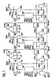
- FIG. 1 shows three segments of a bus of which only two bit lines have been represented for reasons of clarity.
- Bit lines B01, B11 belong to the first segment
- bit lines B02, B12 belong to the second segment
- bit lines B03, B13 belong to the third segment.
- the part of the bus which has been represented corresponds to a single bit of digital information which may include other bits associated with other bit lines not shown.
- Each pair of bit lines such as B01, B11 is connected to the output lines of one or more binary circuits such as M1, which may for example be a memory point or the output circuit associated with a single bit of an operator.
- the binary circuits M2 and M3 are connected respectively to a pair of bit lines of the second and of the third bus segment.
- each binary circuit such as M1, M2, M3 is put into communication with the corresponding bit lines by the action of a selection signal SM1, SM2, SM3 coming from a selection and activation circuit 14, 24, 34 in response to preset and control signals SEL1-SEL3, RD1-RD3, WR1-WR3, PH2, PH3.
- Each pair of bit lines is connected to an amplification device A1, A2, A3 controlled by an activation signal, respectively CA1, CA2, CA3.
- amplification devices can be conventional sense amplifiers commonly used in the memory technique for example.
- Each bit line of a segment is connected to the homologous bit line belonging to an adjacent segment by means of a switch S01, S11, S02, S12.
- a switch S01, S11, S02, S12. For a bus carrying information of several bits, we will thus place as many switches as the bus has lines. All the switches located between two adjacent segments are controlled by the same selection signal C12, C23 which, for a determined logic value, puts these switches in the closed state.
- the three bus segments are respectively associated with the control lines NAC1, NAC2, NAC3.
- Each of the control lines is connected to the input of an amplification circuit 15, 25, 35, the output of which delivers the activation signal CA1, CA2, CA3 from the corresponding amplifier. Thanks to this arrangement, the voltage present on one of the control lines determines the activation of the amplifier of the segment associated with this line. In the perspective of an implementation in CMOS technology, it is in fact the discharge of the line which causes the activation of the corresponding amplifier. Thus to trigger the amplification, it will suffice to provide means for discharging the line that was initially preloaded at a positive voltage.
- the line NAC2 associated with the second segment is connected to ground via a switch 13.
- This switch is controlled by the output signal T1 from a transfer device 16 receiving as input the selection signal C12 of the switches placed between the first two segments.
- the transfer device is also connected at the input to the two control lines NAC1 and NAC2 associated with the first two segments.
- the transfer device 16 is designed so that the signal T1 which it delivers makes the switch 13 conductive when any of the lines NAC1, NAC2 is discharged, provided that the selection signal C12 has the logic value which corresponds when the switches it controls are put into the on state.
- control line NAC1 of the first segment is also connected to a switch 12 also controlled by the output signal T1 from the transfer device 16.
- control line NAC3 associated with the third segment is connected to a switch 23 controlled by another transfer device 26 receiving the switch selection signal placed between the second and the third segment.
- the output signal T2 of the transfer device 26 is applied to the control input of the switch 23.
- the second control line is connected to another switch 22 controlled by the signal T2.
- control lines NAC1, NAC2, NAC3 are also connected to a supply voltage source Vdd by means of switch PC1, PC2, PC3. Each of these switches is controlled by a clock signal PH0.
- control lines NAC1, NAC2, NAC3 are connected to ground by means of additional switches respectively 11, 21, 31 respectively controlled by the signals AC1, AC2, AC3 respectively from circuits 14, 24, 34
- These selection and activation circuits 14, 24, 34 are designed so that they deliver a signal controlling the closing of the corresponding switch 11, 21, 31 when a read control signal RD1, RD2, RD3. is present at their entrance. This arrangement makes it possible to trigger the operation of the control device as soon as a segment is selected for reading.
- FIG. 1 represents only three bus segments, it is obvious that the embodiment described can be generalized for any number of segments.
- the bus control means have a modular structure deduced from the structure of the bus itself.
- the control module can thus constitute a standard cell integrated into a CAD (Computer Aided Design) system.
- CAD Computer Aided Design
- the device operates in at least two phases, one of which corresponds to a precharge phase defined by a clock signal PH0. The purpose of this phase is to charge the control lines at a positive voltage Vdd.
- the read control signals RD1 and selection SEL1 of the first segment are applied to the selection and activation circuit 14. Likewise the selection signals C12 and C23 of the switches are active.
- the circuit 14 delivers on the one hand the selection signal SM1 from one of the circuits of the first segment and on the other hand the control signal AC1 of the discharge switch 11 of the control line NAC1 associated with this segment.
- the circuit M1 is put into communication with the bit lines B01, B11.
- control line NAC1 is discharged by means of the switch 11.
- This discharge activates the amplification circuit 15 which outputs an activation signal CA1 from the amplification device A1.
- the discharge of the control line is detected by the transfer device 16 validated by the selection signal C12.
- the transfer device then causes the activation of the switch 13 of the adjacent line NAC2 causing the discharge of this line.
- this discharge causes the activation of amplifier A2 of the second bus segment.
- the transfer device 26 validated by the signal C23 causes the activation of the switch 23 of the following command line NAC3 which causes the activation of the amplifier A3 of the third segment.
- the write command signal WR3 is applied to the activation and selection circuit 34 as well as the signal preselection SEL3 of circuit M3.
- the circuit 34 delivers the selection signal SM3 to the selected circuit M3.
- This circuit M3 is then placed in communication with the lines B03, B13 whose voltages are at levels allowing writing, thanks to the action of the three amplifiers A1, A2, A3.
- the operation described above in a particular case is easily generalized.
- the number of intermediate segments placed between the first and the last segment can be increased. It is also possible to write-order several segments simultaneously.
- the device can operate bidirectionally. It can also control the transfer of information on either side of the segment ordered for reading.
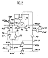
- FIG. 2 represents a more detailed embodiment of the circuits mentioned with reference to FIG. 1.
- This figure shows the two bit lines B01, B11 of the first segment to which the amplification device A1 is connected.
- This segment is connected to an adjacent segment by means of NMOS transistors, S01, S11.
- the drain-source path of each of these transistors is connected in series with the two homologous lines of the two adjacent segments.
- the transistor S01 connects the line B01 of the first segment to the line B02 of the second segment.
- transistor S11 connects line B11 to line B12. This arrangement is reproduced as many times as the information words contain bits.
- the control line NAC1 is connected to the drain of a PMOS-type transistor PC1 (the p-channel MOS transistors are symbolized by a small circle placed on their gate), the source of which is connected to the supply voltage Vdd.
- the gate of this transistor receives the complementary signal NPH0 from the clock signal PH0.
- This transistor PC1 constitutes the means for precharging the control line.
- the control line NAC1 is also connected to the drain of a transistor 12 of the NMOS type, the source of which is connected to ground.
- the adjacent control line NAC2 is connected to the drain of another transistor 13 of NMOS type having its source connected to ground.
- the two transistors 12 and 13 constitute the means for discharging the lines NAC1 and NAC2 respectively.
- the gates of these transistors receive the output signal T1 from the transfer device 16.
- This device consists of an AND gate 17, the two inputs of which are connected respectively to the two control lines NAC1, NAC2.
- the output of this AND gate is connected to an input of a NOR gate 18 whose output provides the signal T1.
- the second input of gate 18 receives the signal C12 from the NAND gate 20.
- This gate receives as input the clock signal PH2 defining the reading phase and the signal SW12 controlling the placing in series of the first and of the second segment.
- the signal C12 is also applied to the input of a power inverter 19, the output of which is connected to the gates of the transistors such as S01, S11 connecting the two adjacent segments.
- the control line NAC1 is connected to the input of an amplification circuit 15 comprising a power inverter 51 whose output provides the activation signal CA1 of the amplifier A1.
- the output of this inverter is also connected to the input of a second inverter 52 whose output is connected to the input of the first inverter 51.
- These two inverters constitute a flip-flop having the dual function of amplifying the signal NAC1 and of maintaining the voltage present on the NAC1 control line.
- the control line NAC1 is also connected to the drain of a transistor 11 of the NMOS type, the source of which is connected to ground.
- the gate of this transistor receives the signal AC1 from circuit 14.
- This latter transistor 11 constitutes the second discharge means described in FIG. 1.
- the signal SW12 takes the logic value 1, which corresponds to a preselection of the closing of the switches connecting the two adjacent segments.
- the clock signal PH0 takes the logic value 1 and the complementary signal NPH0 takes the value 0. It follows that the p-type transistor PC1 is made conductive during this phase. Line NAC1 then charges at a positive voltage Vdd. Note that all the bus command lines will be loaded in the same way.
- the clock signal PH2 takes the logic value 1 and the output signal of the gate 20 takes the logic value 0 while the output voltage NC12 of the power inverter 19 becomes positive making it passable transistors S01, S11.
- the signal AC1 will take the logical value 1 during this phase.
- the transistor 11 will then be conductive, thus discharging the line NAC1.
- the discharge of this line will have two consequences: on the one hand the output of the power inverter 51 will take the logic value 1 thus activating the amplifier A1 of the segment; on the other hand the output of the AND gate 17 will take the logic 0 value and the output T1 of the NOR gate 18 will take a positive voltage thus making the discharge transistor 13 of the line NAC2 conductive.
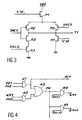
- FIG. 3 represents an embodiment in CMOS technology of the transfer device 16.
- a first transistor P1 of PMOS type the source of which is connected to the supply voltage Vdd receives on its gate the selection signal C12. Its drain is connected to the sources of two other transistors P2, P3 of the PMOS type, the gates of which are connected respectively to the two control lines NAC1 and NAC2. The drains of the two transistors P2, P3 are interconnected, thus constituting the output T1 of the device.
- This point is then connected to the drain of a fourth transistor N1 of NMOS type, the source of which is connected to ground and the gate of which receives the signal C12.
- This same common point is also connected to the drain of a fifth transistor of the NMOS type, the gate of which receives the signal NAC1 and the source of which is connected to the drain of a sixth NOS transistor N3 of which the gate receives the signal NAC2 and the source of which is connected to ground.
- FIG. 4 represents an embodiment of any of the selection and activation circuits 14, 24, 34 shown in FIG. 1.
- This circuit comprises a first AND gate 41 whose two inputs respectively receive the control signal RD1 reading of the bus segment associated with this circuit.
- the other input of the AND gate 41 receives the clock signal PH2 defining the reading phase.
- the output of this AND gate 41 delivers the signal AC1 controlling the discharge of the switch 11.
- a write command signal WR and the clock signal PH3 defining the write phase are applied to the input of a second AND gate 42.
- the outputs of the two AND gates 41, 42 are connected to the input of an OR gate 43.
- FIG. 4 also shows by way of example a fourth AND gate 45 with two inputs receiving respectively the signals PH and SEL11 for preselection of a second circuit of the segment.
- the AND gate 45 delivers the signal SM11 for selecting this circuit. Additional AND gates connected in the same way can be provided if the bus segment is connected to other separately selectable circuits, as is the case for a register bank.
- the circuit of Figure 4 operates as follows. In the case of a read or write command, one of the preset signals SEL1, SEL11 ... takes the logical value 1. If it is a read, the read control signal RD1 has the logical value 1 and the signal AC1 takes this same logical value 1 during the reading phase PH2. Similarly, the signal PH will have the logic value 1 and one of the selection signals SM1, SM11 ... of the preselected circuit will take this same value during the phase PH2. If on the other hand it is a write, the signal WR1 will have the logic value 1, the output of the AND gate 42 taking this same value 1 during the write phase PH3. This will result in setting during this phase PH3 of one of the selection signals SM1, SM11 ... of the circuit preselected for writing. Signal AC1 will keep the logic value 0.
- this circuit allows the activation of the second discharge means 11 of the control line NAC1 associated with the bus segment on which one of these circuits has been selected for reading.
- the associated command line is not discharged under the action of the signal AC1.
- the effective selection of one of the circuits of the segment will take place during the read phase PH2 if the read control signal RD1 is active and during the write phase PH3 if the write control signal WR1 is active.
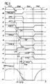
- FIG. 5 represents the timing diagrams of the main signals intervening in the control device according to the invention in the particular case already mentioned where three bus segments would be involved to effect the transfer of information between the first segment selected for reading and the third segment selected in writing.
- the timing diagram A represents the signals defining the four clock phases PH0, PH1, PH2, PH3 used for sequencing the central unit of a computer.
- the PH2 phase is dedicated to read operations
- the PH3 phase to write operations
- the PH0, PH1 phases define the precharge and equalization phases of the bus line voltages.
- Chronogram B represents the selection signals C12 and C23 applied to the switches respectively connecting the first segment to the second segment and the second segment to the third segment.
- the timing diagram C represents the signal SM1 for selecting one of the circuits of the first segment.
- the timing diagram D represents the signal AC1 controlling the discharge switch 11 of the line NAC1.
- the timing diagrams E, G and I respectively represent the voltages present on the three control lines NAC1, NAC2 and NAC3.
- the timing diagrams F and H represent the control signals T1 and T2 respectively from the transfer devices 16 and 26.
- the timing diagrams J, K and L respectively represent the control signals CA1, CA2 and CA3 applied to the three amplifiers A1, A2, A3 of the three segments involved.
- the timing diagram M represents the selection signal SM3 applied to one of the circuits M3 of the third bus segment.
- the timing diagram N represents the variations as a function of time of the voltage present on one of the bit lines of the first segment. This timing diagram corresponds to the case where the bit lines are normally preloaded at a voltage of five volts while the binary value read imposes that the voltage of this line corresponds to a zero voltage.
- the reading phase PH2 begins at time t0 and at this time the bit lines and the control lines are preloaded at the supply voltage.
- the selection signals C12 and C23 are kept at the logic value 0 while the signals SM1 and AC1 keep the logic value 1.
- Setting the signal AC1 to 1 discharges the control line NAC1 which, after a slight delay due to the time constant of this line, goes to the logical value 0 at time t1. This brings the signal CA1 to logic 1 at time t ⁇ 1.
- the signal T1 appearing at the output of the transfer device 16 goes to logic value 1 and this signal causes the discharge of the line NAC2 at the instant t2, after a delay due to the time constant of this line.
- the discharge of line NAC2 in turn causes logic 1 to be set at time t CA2 of the signal CA2 for controlling the amplifier of the second segment.
- This discharge also causes the signal T2 present at the output of the second transfer device 26 to be put to logic 1.
- the signal T2 then causes the command line NAC3 to be discharged, which then takes the logic value 0 at time t3.
- This discharge then causes the signal CA3 to be set to 1, which then activates the amplifier of this third segment.
- the voltage represented on the timing diagram N reflects the successive activations of the three amplifiers A1, A2, A3 respectively at times t ⁇ 1, t ⁇ 2, t ⁇ 3.
- the selection signal SM3 of one of the circuits of the third segment takes the value 1 logic allowing writing in this circuit, during this phase.
- phase PH0 the precharge switches PC1, PC2, PC3 are closed, which causes all the bus control lines to be set to 1.
- the signals T1 and T2 are reset to zero as well as the control signals of the amplifiers CA1, CA2, CA3.
- the corresponding amplifiers A1, A2, A3 are then deactivated, which then allows the preloading of the bus lines.
- control device shows that the activation of the amplifiers is carried out successively by a propagation of the control signals accompanying the propagation of the information transmitted by the different bus segments.
- the capacity of the control lines must be sufficient to introduce time constants introducing an appropriate delay between the activation of two successive amplifiers to leave them sufficient amplification time.
- the capacity of the control lines can be easily calculated and obtained by dimensioning the structure capacities of the MOS transistors used.
Description
L'invention concerne un dispositif permettant de commander la mise en communication de plusieurs segments de bus isolables électriquement. Chaque segment étant relié généralement aux bornes de sortie de circuits pouvant émettre ou recevoir des informations numériques, la mise en communication de deux ou plusieurs segments permet alors des échanges d'informations entre les circuits d'un des segments et les circuits d'un autre segment (voir US-A-4296469 par exemple).The invention relates to a device for controlling the communication of several electrically isolable bus segments. Each segment being generally connected to the output terminals of circuits that can transmit or receive digital information, the communication of two or more segments then allows information to be exchanged between the circuits of one of the segments and the circuits of another. segment (see US-A-4296469 for example).
Des bus pouvant être subdivisés en plusieurs segments trouvent une application intéressante notamment dans les unités de traitement des ordinateurs. En effet, pour pouvoir faire travailler simultanément et indépendamment plusieurs sous-ensembles fonctionnels de l'unité, il est nécessaire de pouvoir isoler les circuits de ces sous-ensembles. D'autre part, on doit pouvoir également mettre en communication deux sous-ensembles fonctionnels entre eux. Comme exemple de sous-ensembles, on peut citer les opérateurs, les registres ou les bancs de registres. Pour résoudre le problème précédent une solution consiste à prévoir des moyens permettant d'isoler à volonté des segments du bus, chaque segment étant relié aux circuits constituant un sous-ensemble fonctionnel.Buses which can be subdivided into several segments find an interesting application in particular in the processing units of computers. Indeed, to be able to make several functional sub-assemblies of the unit work simultaneously and independently, it is necessary to be able to isolate the circuits of these sub-assemblies. On the other hand, we must also be able to put two functional subsets into communication with each other. As an example of subsets, we can cite operators, registers or banks of registers. To solve the previous problem, a solution consists in providing means making it possible to isolate segments of the bus at will, each segment being connected to the circuits constituting a functional sub-assembly.
Pour réaliser des bus constitués par plusieurs segments isolables, on utilise des interrupteurs commandés, un interrupteur reliant deux lignes homologues de deux segments adjacents. Ces interrupteurs sont commandés par des signaux de sélection issus de l'unité de commande de l'ordinateur. L'état logique des signaux de sélection définit ainsi une certaine configuration du bus. Plusieurs segments pourront être mis en série alors que d'autres seront totalement isolés.To make buses made up of several isolable segments, controlled switches are used, a switch connecting two homologous lines of two adjacent segments. These switches are controlled by selection signals from the computer control unit. The logic state of the selection signals thus defines a certain configuration of the bus. Several segments can be put in series while others will be completely isolated.
La réalisation de tels bus ne présente pas de grande difficulté lorsque le nombre de segments est relativement faible. Par contre si l'on veut augmenter les possibilités de parallèlisme, il est souhaitable de disposer de bus pouvant être subdivisés en de nombreux segments indépendants. Il faut pouvoir aussi mettre en communication deux ou plusieurs segments quelconques, ce qui peut conduire à une situation où la capacité totale du bus est très élevée. Il convient alors d'utiliser des moyens permettant de maintenir à un niveau suffisant sur toute la longueur du bus les tensions des signaux transmis. Pour cela chaque segment du bus est associé à des moyens d'amplification qui sont activés chaque fois que le segment travaille en émission, en transmission ou en réception.The realization of such buses does not present any great difficulty when the number of segments is relatively low. On the other hand, if one wishes to increase the possibilities of parallelism, it is desirable to have buses which can be subdivided into numerous independent segments. It must also be possible to connect two or more arbitrary segments, which can lead to a situation where the total capacity of the bus is very high. Means should then be used to maintain the voltages of the transmitted signals at a sufficient level over the entire length of the bus. For this, each segment of the bus is associated with amplification means which are activated each time the segment works in transmission, in transmission or in reception.
Il convient alors de prévoir aussi des moyens de commande, notamment des dispositifs d'amplification, permettant un fonctionnement correct de cet ensemble. En particulier l'activation de l'amplificateur associé à un segment doit être retardée par rapport à celle du segment adjacent par lequel vient l'information. En effet, si l'on négligeait cette contrainte, on risquerait de créer un état d'instabilité pouvant conduire à un fonctionnement anarchique des amplificateurs.It is then advisable to also provide control means, in particular amplification devices, allowing correct operation of this assembly. In particular, the activation of the amplifier associated with a segment must be delayed compared to that of the adjacent segment from which the information comes. Indeed, if this constraint were neglected, there would be a risk of creating a state of instability which could lead to an anarchic operation of the amplifiers.
Ainsi l'invention propose un dispositif de commande d'un tel bus selon lequel l'activation de l'amplificateur d'un segment quelconque est asservi à l'activation de l'amplificateur de celui des segments adjacents qui a déjà été activé.Thus the invention proposes a device for controlling such a bus according to which the activation of the amplifier of any segment is subject to the activation of the amplifier of that of the adjacent segments which has already been activated.
Plus précisément l'invention a pour objet un dispositif de commande de bus constitué par plusieurs segments isolables, permettant le transfert d'informations d'un segment à un autre, deux segments adjacents étant reliés entre eux par des interrupteurs commandés par un signal de sélection, un dispositif d'amplification commandé par un signal d'activation étant associé à chaque segment du bus pour amplifier les tensions apparaissant sur les lignes dudit segment, ledit dispositif de commande étant caractérisé en ce qu'il comprend des moyens d'asservissement pour activer l'amplificateur d'un segment quelconque en réponse à l'activation de l'amplificateur d'un segment adjacent audit segment et au signal de sélection des interrupteurs reliant ledit segment audit segment adjacent.More specifically, the subject of the invention is a bus control device constituted by several isolable segments, allowing the transfer of information from one segment to another, two adjacent segments being interconnected by switches controlled by a selection signal. , an amplification device controlled by a activation signal being associated with each segment of the bus to amplify the voltages appearing on the lines of said segment, said control device being characterized in that it comprises servo means for activating the amplifier of any segment by response to the activation of the amplifier of a segment adjacent to said segment and to the selection signal of the switches connecting said segment to said adjacent segment.
Les sous-ensembles fonctionnels connectés à un segment de bus peuvent être des éléments utilisés en lecture seule comme par exemple des opérateurs ou bien des éléments pouvant travailler en lecture ou en écriture, comme par exemple des registres. Ainsi un bus constitué par plusieurs segments doit pouvoir véhiculer des informations de façon bidirectionnelle. Il convient donc que le dispositif de commande des interrupteurs et des amplificateurs permette ce fonctionnement bidirectionnel.The functional sub-assemblies connected to a bus segment can be elements used in read-only mode such as for example operators or else elements which can work in reading or writing, such as for example registers. Thus a bus made up of several segments must be able to convey information bidirectionally. The switch and amplifier control device should therefore allow this bidirectional operation.
Le dispositif de commande est enfin conçu pour pouvoir être déclenché lors de la sélection en lecture d'un segment quelconque du bus.Finally, the control device is designed so that it can be triggered during the selection for reading of any segment of the bus.
Aussi l'invention propose également un mode de réalisation du dispositif de commande qui permet de satisfaire à ces contraintes.Also, the invention also proposes an embodiment of the control device which makes it possible to satisfy these constraints.
L'invention concerne également une réalisation modulaire du dispositif de commande, chaque module étant associé à un segment du bus. Plus précisément, chaque module comprend une ligne de commande préchargée dont la décharge active l'amplificateur du segment de bus associé, la décharge de cette ligne pouvant être commandée par la décharge d'une ligne de commande associée à l'un des segments adjacents.The invention also relates to a modular embodiment of the control device, each module being associated with a segment of the bus. More precisely, each module comprises a preloaded control line, the discharge of which activates the amplifier of the associated bus segment, the discharge of this line being able to be controlled by the discharge of a control line associated with one of the adjacent segments.
Outre sa simplicité, cette solution présente l'avantage que l'on peut facilement connecter à la ligne de commande des moyens de décharge additionnels commandés par d'autres signaux et réaliser ainsi une fonction OU logique. En particulier, ce moyen de décharge supplémentaire peut être activé en réponse à un signal de commande de lecture de l'un des circuits relié au segment associé à la ligne, permettant ainsi de déclencher le fonctionnement de la commande.In addition to its simplicity, this solution has the advantage that one can easily connect to the control line additional discharge means controlled by other signals and thus perform a logical OR function. In particular, this additional discharge means can be activated in response to a read command signal from one of the circuits connected to the segment associated with the line, thus making it possible to trigger the operation of the command.
Enfin l'invention propose une réalisation très simple utilisant la technologie CMOS.Finally, the invention proposes a very simple embodiment using CMOS technology.
Ces détails de réalisation ainsi que d'autres caractéristiques apparaîtront dans le mode de réalisation préférentiel décrit dans la description qui va suivre :
- La figure 1 représente schématiquement un dispositif de commande selon l'invention associé à trois segments de bus.
- La figure 2 représente un mode de réalisation d'un module faisant partie du dispositif de commande selon l'invention.
- La figure 3 représente une réalisation en technologie CMOS d'un dispositif de transfert faisant partie du dispositif représenté à la figure 2.
- La figure 4 représente une réalisation d'un circuit de sélection et d'activation faisant partie du dispositif de commande selon l'invention.
- La figure 5 représente des chronogrammes permettant d'expliquer le fonctionnement du dispositif de commande selon l'invention.
- FIG. 1 schematically represents a control device according to the invention associated with three bus segments.
- FIG. 2 represents an embodiment of a module forming part of the control device according to the invention.
- FIG. 3 represents an embodiment in CMOS technology of a transfer device forming part of the device represented in FIG. 2.
- FIG. 4 represents an embodiment of a selection and activation circuit forming part of the control device according to the invention.
- FIG. 5 represents timing diagrams making it possible to explain the operation of the control device according to the invention.
La figure 1 montre trois segments d'un bus dont seulement deux lignes de bit ont été représentées pour des raisons de clarté. Les lignes de bit B01, B11 appartiennent au premier segment, les lignes de bit B02, B12 appartiennent au second segment et les lignes de bit B03, B13 appartiennent au troisième segment. La partie du bus qui a été représentée correspond à un seul bit d'une information numérique pouvant comprendre d'autres bits associés d'autres lignes de bit non représentées. Chaque paire de lignes de bit telle que B01, B11 est connectée aux lignes de sortie d'un ou plusieurs circuits binaires tels que M1 pouvant être par exemple un point mémoire ou le circuit de sortie associé à un seul bit d'un opérateur. De même les circuits binaires M2 et M3 sont connectés respectivement à une paire de lignes de bit du second et du troisième segment de bus. Il est bien entendu que plusieurs circuits binaires peuvent être connectés aux mêmes lignes d'un même segment. Ce sera par exemple le cas pour un banc de registre associé à un même segment. Chaque circuit binaire tel que M1, M2, M3 est mis en communication avec les lignes de bit correspondantes par l'action d'un signal de sélection SM1, SM2, SM3 issu d'un circuit de sélection et d'activation 14, 24, 34 en réponse à des signaux de présélection et de commande SEL1-SEL3, RD1-RD3, WR1-WR3, PH2, PH3.FIG. 1 shows three segments of a bus of which only two bit lines have been represented for reasons of clarity. Bit lines B01, B11 belong to the first segment, bit lines B02, B12 belong to the second segment and bit lines B03, B13 belong to the third segment. The part of the bus which has been represented corresponds to a single bit of digital information which may include other bits associated with other bit lines not shown. Each pair of bit lines such as B01, B11 is connected to the output lines of one or more binary circuits such as M1, which may for example be a memory point or the output circuit associated with a single bit of an operator. Similarly, the binary circuits M2 and M3 are connected respectively to a pair of bit lines of the second and of the third bus segment. It is understood that several binary circuits can be connected to the same lines of the same segment. This will for example be the case for a register bank associated with the same segment. Each binary circuit such as M1, M2, M3 is put into communication with the corresponding bit lines by the action of a selection signal SM1, SM2, SM3 coming from a selection and
Chaque paire de lignes de bit est reliée à un dispositif d'amplification A1, A2, A3 commandé par un signal d'activation, respectivement CA1, CA2, CA3. Ces dispositifs d'amplification peuvent être des amplificateurs de lecture classiques couramment utilisés dans la technique des mémoires par exemple.Each pair of bit lines is connected to an amplification device A1, A2, A3 controlled by an activation signal, respectively CA1, CA2, CA3. These amplification devices can be conventional sense amplifiers commonly used in the memory technique for example.
Chaque ligne de bit d' un segment est reliée à la ligne de bit homologue appartenant à un segment adjacent par l'intermédiaire d'un interrupteur S01, S11, S02, S12. Pour un bus véhiculant les informations de plusieurs bits, on placera ainsi autant d'interrupteurs que le bus a de lignes. Tous les interrupteurs situés entre deux segments adjacents sont commandés par un même signal de sélection C12, C23 qui, pour une valeur logique déterminée, met ces interrupteurs à l'état fermé.Each bit line of a segment is connected to the homologous bit line belonging to an adjacent segment by means of a switch S01, S11, S02, S12. For a bus carrying information of several bits, we will thus place as many switches as the bus has lines. All the switches located between two adjacent segments are controlled by the same selection signal C12, C23 which, for a determined logic value, puts these switches in the closed state.
Les trois segments de bus sont associés respectivement aux lignes de commande NAC1, NAC2, NAC3. Chacune des lignes de commande est reliée à l'entrée d'un circuit d'amplification 15, 25, 35 dont la sortie délivre le signal d'activation CA1, CA2, CA3 de l'amplificateur correspondant. Grâce à cette disposition, la tension présente sur une des lignes de commande détermine l'activation de l'amplicateur du segment associé à cette ligne. Dans la perspective d'une réalisation en technologie CMOS, c'est en fait la décharge de la ligne qui entraîne l'activation de l'amplificateur correspondant. Ainsi pour déclencher l'amplification, il suffira de prévoir des moyens pour décharger la ligne initialement préchargée à une tension positive.The three bus segments are respectively associated with the control lines NAC1, NAC2, NAC3. Each of the control lines is connected to the input of an
Par exemple la ligne NAC2 associée au second segment est reliée à la masse par l'intermédiaire d'un interrupteur 13. Cet interrupteur est commandé par le signal de sortie T1 d'un dispositif de transfert 16 recevant en entrée le signal de sélection C12 des interrupteurs placés entre les deux premiers segments. Le dispositif de transfert est également relié en entrée aux deux lignes de commande NAC1 et NAC2 associées aux deux premiers segments. Le dispositif de transfert 16 est conçu de sorte que le signal T1 qu'il délivre rende conducteur l'interrupteur 13 lorsque l'une quelconque des lignes NAC1, NAC2 est déchargée, à condition que le signal de sélection C12 ait la valeur logique qui correspond à la mise à l'état passant des interrupteurs qu'il commande.For example, the line NAC2 associated with the second segment is connected to ground via a
D'autre part, la ligne de commande NAC1 du premier segment est reliée également à un interrupteur 12 commandé également par le signal de sortie T1 du dispositif de transfert 16.On the other hand, the control line NAC1 of the first segment is also connected to a
De façon analogue, la ligne de commande NAC3 associée au troisième segment est reliée à un interrupteur 23 commandé par un autre dispositif de transfert 26 recevant le signal de sélection des interrupteurs placé entre le second et le troisième segment. Le signal de sortie T2 du dispositif de transfert 26 est appliqué à l'entrée de commande de l'interrupteur 23. De même, la deuxième ligne de commande est reliée à un autre interrupteur 22 commandé par le signal T2.Similarly, the control line NAC3 associated with the third segment is connected to a
Les lignes de commande NAC1, NAC2, NAC3 sont en outre reliées à une source de tension d'alimentation Vdd par l'intermédiaire d'interrupteur PC1, PC2, PC3. Chacun de ces interrupteurs est commandé par un signal d'horloge PH0.The control lines NAC1, NAC2, NAC3 are also connected to a supply voltage source Vdd by means of switch PC1, PC2, PC3. Each of these switches is controlled by a clock signal PH0.
Enfin, les trois lignes de commande NAC1, NAC2, NAC3 sont reliées à la masse par l'intermédiaire d'interrupteurs supplémentaires respectivement 11, 21, 31 commandés respectivement par les signaux AC1, AC2, AC3 issus respectivement des circuits 14, 24, 34. Ces circuits de sélection et d'activation 14, 24, 34 sont conçus de sorte qu'ils délivrent un signal commandant la fermeture de l'interrupteur 11, 21, 31 correspondant lorsqu'un signal de commande de lecture RD1, RD2, RD3 est présent à leur entrée. Cette disposition permet de déclencher le fonctionnement du dispositif de commande dès qu'un segment est sélectionné en lecture.Finally, the three control lines NAC1, NAC2, NAC3 are connected to ground by means of additional switches respectively 11, 21, 31 respectively controlled by the signals AC1, AC2, AC3 respectively from
Bien que la figure 1 ne représente que trois segments de bus, il est évident que la réalisation décrite peut être généralisée pour un nombre quelconque de segments. Pour cela, il suffira de reproduire pour chaque segment les éléments qui ont été décrits par exemple pour le second segment B02, B12 représenté à la figure 1: une ligne de commande NAC2, un moyen de décharge 22 de cette ligne, un dispositif de transfert 26 commandant ce moyen de décharge 22, un moyen de décharge 23 de la ligne adjacente, le moyen de précharge PC2 et éventuellement des moyens supplémentaires de décharge 21 prévu dans le cas où les circuits binaires connectés au segment sont susceptibles d'être lus. Ainsi les moyens de commande du bus ont une structure modulaire déduite de la structure du bus lui-même. Le module de commande peut ainsi constituer une cellule standard intégrée dans un système de CAO (Conception Assistée par Ordinateur).Although FIG. 1 represents only three bus segments, it is obvious that the embodiment described can be generalized for any number of segments. For this, it will suffice to reproduce for each segment the elements which have been described for example for the second segment B02, B12 represented in FIG. 1: a control line NAC2, a discharge means 22 for this line, a
Nous allons maintenant décrire le fonctionnement du dispositif de commande de la figure 1. Nous nous placerons à titre d'illustration dans le cas particulier du transfert d'une information issue d'un circuit du premier segment vers le troisième segment où cette information doit être mémorisée. Le dispositif fonctionne en deux phases au moins dont l'une correspond à une phase de précharge définie par un signal d'horloge PH0. Cette phase a pour but de charger les lignes de commandes à une tension positive Vdd. Par ailleurs, selon l'exemple choisi, les signaux de commande de lecture RD1 et de sélection SEL1 du premier segment sont appliqués au circuit de sélection et d'activation 14. De même les signaux de sélection C12 et C23 des interrupteurs sont actifs. Lors de la phase de lecture définie par un second signal d'horloge PH2, le circuit 14 délivre d'une part le signal de sélection SM1 de l'un des circuits du premier segment et d'autre part le signal de commande AC1 de l'interrupteur de décharge 11 de la ligne de commande NAC1 associée à ce segment. Il en résulte que le circuit M1 est mis en communication avec les lignes de bits B01, B11.We will now describe the operation of the control device of FIG. 1. We will place ourselves by way of illustration in the particular case of the transfer of information coming from a circuit of the first segment to the third segment where this information must be memorized. The device operates in at least two phases, one of which corresponds to a precharge phase defined by a clock signal PH0. The purpose of this phase is to charge the control lines at a positive voltage Vdd. Furthermore, according to the example chosen, the read control signals RD1 and selection SEL1 of the first segment are applied to the selection and
D'autre part la ligne de commande NAC1 se décharge par l'intermédiaire de l'interrupteur 11. Cette décharge actionne le circuit d'amplification 15 qui délivre en sortie un signal d'activation CA1 du dispositif d'amplification A1. Par ailleurs, la décharge de la ligne de commande est détectée par le dispositif de transfert 16 validé par le signal de sélection C12. Le dispositif de transfert provoque alors l'activation de l'interrupteur 13 de la ligne adjacente NAC2 provoquant la décharge de cette ligne. De façon analogue cette décharge provoque l'activation de l'amplificateur A2 du second segment de bus. De même le dispositif de transfert 26 validé par le signal C23 provoque l'activation de l'interrupteur 23 de la ligne de commande suivante NAC3 ce qui provoque l'activation de l'amplificateur A3 du troisième segment.On the other hand, the control line NAC1 is discharged by means of the
D'après cet exemple, l'information issue du premier segment devant être écrite dans l'un des circuits M3 du troisième segment, le signal de commande d'écriture WR3 est appliqué au circuit d'activation et de sélection 34 ainsi que le signal de présélection SEL3 du circuit M3. Lorsque le signal d'horloge PH3 définissant la phase d'écriture est actif, le circuit 34 délivre le signal de sélection SM3 au circuit M3 sélectionné. Ce circuit M3 est alors mis en communication avec les lignes B03, B13 dont les tensions sont à des niveaux permettant l'écriture, grâce à l'action des trois amplificateurs A1, A2, A3.According to this example, the information coming from the first segment having to be written in one of the circuits M3 of the third segment, the write command signal WR3 is applied to the activation and
Le fonctionnement décrit précédemment dans un cas particulier se généralise facilement. En particulier, on peut augmenter le nombre de segments intermédiaires placés entre le premier et le dernier segment. Il est possible également de commander en écriture plusieurs segments simultanément. Enfin le dispositif peut fonctionner de façon bidirectionnelle. Il peut également commander le transfert d'informations de part et d'autre du segment commandé en lecture.The operation described above in a particular case is easily generalized. In particular, the number of intermediate segments placed between the first and the last segment can be increased. It is also possible to write-order several segments simultaneously. Finally, the device can operate bidirectionally. It can also control the transfer of information on either side of the segment ordered for reading.
La figure 2 représente une réalisation plus détaillée des circuits mentionnés en référence à la figure 1. Nous retrouvons sur cette figure les deux lignes de bit B01, B11 du premier segment auxquelles est relié le dispositif d'amplification A1. Ce segment est relié à un segment adjacent par l'intermédiaire de transistors NMOS, S01, S11. Le chemin drain-source de chacun de ces transistors est connecté en série avec les deux lignes homologues des deux segments adjacents. Ainsi le transistor S01 relie la ligne B01 du premier segment à la ligne B02 du second segment. De même le transistor S11 relie la ligne B11 à la ligne B12. Cette disposition est reproduite autant de fois que les mots d'information contiennent de bits.FIG. 2 represents a more detailed embodiment of the circuits mentioned with reference to FIG. 1. This figure shows the two bit lines B01, B11 of the first segment to which the amplification device A1 is connected. This segment is connected to an adjacent segment by means of NMOS transistors, S01, S11. The drain-source path of each of these transistors is connected in series with the two homologous lines of the two adjacent segments. Thus the transistor S01 connects the line B01 of the first segment to the line B02 of the second segment. Likewise, transistor S11 connects line B11 to line B12. This arrangement is reproduced as many times as the information words contain bits.
La ligne de commande NAC1 est reliée au drain d'un transistor PC1 de type PMOS (les transistors MOS à canal p sont symbolisés par un petit rond placé sur leur grille), dont la source est reliée à la tension d'alimentation Vdd. La grille de ce transistor reçoit le signal complémentaire NPH0 du signal d'horloge PH0. Ce transistor PC1 constitue le moyen de précharge de la ligne de commande.The control line NAC1 is connected to the drain of a PMOS-type transistor PC1 (the p-channel MOS transistors are symbolized by a small circle placed on their gate), the source of which is connected to the supply voltage Vdd. The gate of this transistor receives the complementary signal NPH0 from the clock signal PH0. This transistor PC1 constitutes the means for precharging the control line.
La ligne de commande NAC1 est également reliée au drain d'un transistor 12 du type NMOS dont la source est reliée à la masse. De même la ligne de commande adjacente NAC2 est reliée au drain d'un autre transistor 13 de type NMOS ayant sa source reliée à la masse. Les deux transistors 12 et 13 constituent les moyens de décharge respectivement des lignes NAC1 et NAC2. Les grilles de ces transistors reçoivent le signal de sortie T1 du dispositif de transfert 16. Ce dispositif est constitué par une porte ET 17 dont les deux entrées sont reliées respectivement aux deux lignes de commande NAC1, NAC2. La sortie de cette porte ET est reliée à une entrée d'une porte NON-OU 18 dont la sortie fournit le signal T1. La seconde entrée de la porte 18 reçoit le signal C12 issu de la porte NON-ET 20. Cette porte reçoit en entrée le signal d'horloge PH2 définissant la phase de lecture et le signal SW12 commandant la mise en série du premier et du second segment. Le signal C12 est également appliqué à l'entrée d'un inverseur de puissance 19 dont la sortie est reliée aux grilles des transistors tels que S01, S11 reliant les deux segments adjacents.The control line NAC1 is also connected to the drain of a
La ligne de commande NAC1 est reliée à l'entrée d'un circuit d'amplification 15 comprenant un inverseur de puissance 51 dont la sortie fournit le signal d'activation CA1 de l'amplificateur A1. La sortie de cet inverseur est également reliée à l'entrée d'un second inverseur 52 dont la sortie est reliée à l'entrée du premier inverseur 51. Ces deux inverseurs constituent une bascule ayant la double fonction d'amplification du signal NAC1 et de maintien de la tension présente sur la ligne de commande NAC1.The control line NAC1 is connected to the input of an
La ligne de commande NAC1 est en outre reliée au drain d'un transistor 11 de type NMOS dont la source est reliée à la masse. La grille de ce transistor reçoit le signal AC1 issu du circuit 14. Ce dernier transistor 11 constitue les seconds moyens de décharge décrits à la figure 1.The control line NAC1 is also connected to the drain of a
Nous allons maintenant décrire le fonctionnement du circuit représenté à la figure 2 en utilisant la convention de la logique positive. Comme précédemment, nous nous placerons dans le cas où l'on veut transférer des informations à partir du premier segment vers le segment adjacent placé à la droite de la figure. Dans ce cas, le signal SW12 prend la valeur 1 logique, ce qui correspond à une présélection de la fermeture des interrupteurs reliant les deux segments adjacents.We will now describe the operation of the circuit shown in Figure 2 using the convention of positive logic. As before, we will place ourselves in the case where we want to transfer information from the first segment to the adjacent segment placed to the right of the figure. In this case, the signal SW12 takes the
Durant la phase de précharge, le signal d'horloge PH0 prend la valeur 1 logique et le signal complémentaire NPH0 prend la valeur 0. Il en résulte que le transistor PC1 de type p est rendu conducteur durant cette phase. La ligne NAC1 se charge alors à une tension positive Vdd. On peut noter que toutes les lignes de commande du bus se chargeront de la même façon.During the precharging phase, the clock signal PH0 takes the
Lors de la phase de lecture, le signal d'horloge PH2 prend la valeur 1 logique et le signal de sortie de la porte 20 prend la valeur 0 logique tandis que la tension de sortie NC12 de l'inverseur de puissance 19 devient positive rendant passant les transistors S01, S11. Le premier segment étant commandé en lecture, le signal AC1 prendra la valeur 1 logique durant cette phase. Le transistor 11 sera alors conducteur, déchargeant ainsi la ligne NAC1. La décharge de cette ligne aura deux conséquences : d'une part la sortie de l'inverseur de puissance 51 prendra la valeur 1 logique activant ainsi l'amplificateur A1 du segment ; d'autre part la sortie de la porte ET 17 prendra la valeur 0 logique et la sortie T1 de la porte NON-OU 18 prendra une tension positive rendant ainsi conducteur le transistor de décharge 13 de la ligne NAC2.During the reading phase, the clock signal PH2 takes the
La figure 3 représente un mode de réalisation en technologie CMOS du dispositif de transfert 16. Un premier transistor P1 de type PMOS dont la source est reliée à la tension d'alimentation Vdd reçoit sur sa grille le signal de sélection C12. Son drain est relié aux sources de deux autres transistors P2,P3 de type PMOS dont les grilles sont reliées respectivement aux deux lignes de commande NAC1 et NAC2. Les drains des deux transistors P2,P3 sont reliés entre eux, constituant ainsi la sortie T1 du dispositif. Ce point est relié ensuite au drain d'un quatrième transistor N1 de type NMOS dont la source est reliée à la masse et dont la grille reçoit le signal C12. Ce même point commun est relié également au drain d'un cinquième transistor du type NMOS dont la grille reçoit le signal NAC1 et dont la source est reliée au drain d'un sixième transistor N3 de type NMOS dont la grille reçoit le signal NAC2 et dont la source est reliée à la masse.FIG. 3 represents an embodiment in CMOS technology of the
Le fonctionnement de ce circuit est évident et il ne sera donc pas exposé. Il est facile de vérifier que la tension de sortie T1 prend une valeur positive si l'un quelconque des signaux NAC1 et NAC2 a une tension nulle et si le signal C12 a également une tension nulle.The operation of this circuit is obvious and it will therefore not be exposed. It is easy to verify that the output voltage T1 takes a positive value if any of the signals NAC1 and NAC2 has a zero voltage and if the signal C12 also has a zero voltage.
La figure 4 représente un mode de réalisation de l'un quelconque des circuits de sélection et d'activation 14, 24, 34 représenté à la figure 1. Ce circuit comporte une première porte ET 41 dont les deux entrées reçoivent respectivement le signal de commande de lecture RD1 du segment de bus associé à ce circuit. L'autre entrée de la porte ET 41 reçoit le signal d'horloge PH2 définissant la phase de lecture. La sortie de cette porte ET 41 délivre le signal AC1 commandant la décharge de l'interrupteur 11. Un signal de commande d'écriture WR et le signal d'horloge PH3 définissant la phase d'écriture sont appliqués à l'entrée d'une seconde porte ET 42. Les sorties des deux portes ET 41, 42 sont reliées à l'entrée d'une porte OU 43. La sortie PH de la porte OU 43 est appliquée à une entrée d'une troisième porte ET 44 à deux entrées, dont la seconde entrée reçoit le signal SEL1 de présélection de l'un des circuits du segment concerné. La sortie de la porte ET 44 délivre le signal SM1 de sélection de ce circuit. La figure 4 représente également à titre d'exemple une quatrième porte ET 45 à deux entrées recevant respectivement les signaux PH et SEL11 de présélection d'un second circuit du segment. La porte ET 45 délivre le signal SM11 de sélection de ce circuit. Des portes ET supplémentaires branchées de la même façon peuvent être prévues dans le cas où le segment de bus serait relié à d'autres circuits sélectionnables séparément, comme c'est le cas pour un banc de registres.FIG. 4 represents an embodiment of any of the selection and
Le circuit de la figure 4 fonctionne de la façon suivante. Dans le cas d'une commande de lecture ou d'écriture l'un des signaux de présélection SEL1, SEL11... prend la valeur 1 logique. S'il s'agit d'une lecture le signal de commande de lecture RD1 a la valeur 1 logique et le signal AC1 prend cette même valeur 1 logique durant la phase de lecture PH2. De même le signal PH aura la valeur 1 logique et l'un des signaux de sélection SM1, SM11... du circuit préselectionné prendra cette même valeur durant la phase PH2. Si par contre il s'agit d'une écriture, le signal WR1 aura la valeur 1 logique, la sortie de la porte ET 42 prenant cette même valeur 1 durant la phase d'écriture PH3. Il en résultera la mise à 1 durant cette phase PH3 de l'un des signaux de sélection SM1, SM11... du circuit présélectionné pour l'écriture. Le signal AC1 conservera la valeur 0 logique.The circuit of Figure 4 operates as follows. In the case of a read or write command, one of the preset signals SEL1, SEL11 ... takes the
Nous constatons que ce circuit permet bien l'activation des seconds moyens de décharge 11 de la ligne de commande NAC1 associé au segment de bus sur lequel a été sélectionné en lecture l'un de ces circuits. Par contre, lors d'une écriture dans l'un des circuits de ce segment du bus, la ligne de commande associée n'est pas déchargée sous l'action du signal AC1. D'autre part, la sélection effective de l'un des circuits du segment aura lieu durant la phase de lecture PH2 si le signal de commande de lecture RD1 est actif et durant la phase d'écriture PH3 si le signal de commande d'écriture WR1 est actif.We note that this circuit allows the activation of the second discharge means 11 of the control line NAC1 associated with the bus segment on which one of these circuits has been selected for reading. On the other hand, during a writing in one of the circuits of this segment of the bus, the associated command line is not discharged under the action of the signal AC1. On the other hand, the effective selection of one of the circuits of the segment will take place during the read phase PH2 if the read control signal RD1 is active and during the write phase PH3 if the write control signal WR1 is active.
La figure 5 représente les chronogrammes des principaux signaux intervenant dans le dispositif de commande selon l'invention dans le cas particulier déjà mentionné où trois segments de bus seraient impliqués pour effectuer le transfert d'information entre le premier segment sélectionné en lecture et le troisième segment sélectionné en écriture.FIG. 5 represents the timing diagrams of the main signals intervening in the control device according to the invention in the particular case already mentioned where three bus segments would be involved to effect the transfer of information between the first segment selected for reading and the third segment selected in writing.
Le chronogramme A représente les signaux définissant les quatre phases d'horloge PH0, PH1, PH2, PH3 servant au séquencement de l'unité centrale d'un ordinateur. La phase PH2 est consacré aux opérations de lecture, la phase PH3 aux opérations d'écriture et les phases PH0, PH1 définissent des phases de précharge et d'égalisation des tensions des lignes du bus.The timing diagram A represents the signals defining the four clock phases PH0, PH1, PH2, PH3 used for sequencing the central unit of a computer. The PH2 phase is dedicated to read operations, the PH3 phase to write operations and the PH0, PH1 phases define the precharge and equalization phases of the bus line voltages.
Le chronogramme B représente les signaux de sélection C12 et C23 appliqué aux interrupteurs reliant respectivement le premier segment au second segment et le second segment au troisième segment.Chronogram B represents the selection signals C12 and C23 applied to the switches respectively connecting the first segment to the second segment and the second segment to the third segment.
Le chronogramme C représente le signal SM1 de sélection de l'un des circuits du premier segment.The timing diagram C represents the signal SM1 for selecting one of the circuits of the first segment.
Le chronogramme D représente le signal AC1 commandant l'interrupteur de décharge 11 de la ligne NAC1.The timing diagram D represents the signal AC1 controlling the
Les chronogrammes E, G et I représentent respectivement les tensions présentes sur les trois lignes de commande NAC1, NAC2 et NAC3. Les chronogrammes F et H représentent respectivement les signaux de commande T1 et T2 issus des dispositifs de transfert 16 et 26.The timing diagrams E, G and I respectively represent the voltages present on the three control lines NAC1, NAC2 and NAC3. The timing diagrams F and H represent the control signals T1 and T2 respectively from the
Les chronogrammes J, K et L représentent respectivement les signaux de commande CA1, CA2 et CA3 appliqués au trois amplificateurs A1, A2, A3 des trois segments impliqués.The timing diagrams J, K and L respectively represent the control signals CA1, CA2 and CA3 applied to the three amplifiers A1, A2, A3 of the three segments involved.
Le chronogramme M représente le signal de sélection SM3 appliqué à l'un des circuits M3 du troisième segment de bus.The timing diagram M represents the selection signal SM3 applied to one of the circuits M3 of the third bus segment.
Le chronogramme N représente les variations en fonction du temps de la tension présente sur l'une des lignes de bit du premier segment. Ce chronogramme correspond au cas où les lignes de bit sont normalement préchargées à une tension de cinq volts alors que la valeur binaire lue impose que la tension de cette ligne corresponde à une tension nulle.The timing diagram N represents the variations as a function of time of the voltage present on one of the bit lines of the first segment. This timing diagram corresponds to the case where the bit lines are normally preloaded at a voltage of five volts while the binary value read imposes that the voltage of this line corresponds to a zero voltage.
La phase de lecture PH2 débute à l'instant t0 et à cet instant les lignes de bit et les lignes de commande sont préchargées à la tension d'alimentation. Durant la phase PH2, les signaux de sélection C12 et C23 sont maintenus à la valeur 0 logique alors que les signaux SM1 et AC1 gardent la valeur 1 logique. La mise à 1 du signal AC1 provoque la décharge de la ligne de commande NAC1 qui, après un léger retard dû à la constante de temps de cette ligne, passe à la valeur 0 logique à l'instant t1. Ceci entraîne la mise à 1 logique du signal CA1 à l'instant tʹ1. De même le signal T1 apparaissant à la sortie du dispositif de transfert 16 passe à la valeur 1 logique et ce signal entraîne la décharge de la ligne NAC2 à l'instant t2, après un retard dû à la constante de temps de cette ligne. La décharge de la ligne NAC2 provoque à son tour la mise à 1 logique à l'instant tʹ2 du signal CA2 de commande de l'amplificateur du deuxième segment. Cette décharge provoque également la mise à 1 logique du signal T2 présent à la sortie du second dispositif de transfert 26. Le signal T2 provoque alors la décharge de la ligne de commande NAC3 qui prend alors la valeur 0 logique à l'instant t3. Cette décharge provoque alors la mise à 1 du signal CA3 qui active alors l'amplificateur de ce troisième segment.The reading phase PH2 begins at time t0 and at this time the bit lines and the control lines are preloaded at the supply voltage. During phase PH2, the selection signals C12 and C23 are kept at the logic value 0 while the signals SM1 and AC1 keep the
La tension représentée sur le chronogramme N reflète les activations successives des trois amplificateurs A1, A2, A3 respectivement aux instants tʹ1, tʹ2, tʹ3.The voltage represented on the timing diagram N reflects the successive activations of the three amplifiers A1, A2, A3 respectively at times tʹ1, tʹ2, tʹ3.
Durant la phase d'écriture PH3, le signal de sélection SM3 de l'un des circuits du troisième segment prend la valeur 1 logique permettant ainsi l'écriture dans ce circuit, durant cette phase.During the writing phase PH3, the selection signal SM3 of one of the circuits of the third segment takes the
Lors de la phase PH0, les interrupteurs de précharge PC1, PC2, PC3 sont fermés, ce qui provoque la mise à 1 logique de toutes les lignes de commande du bus. Il en résulte que les signaux T1 et T2 sont remis à zéro ainsi que les signaux de commande des amplificateurs CA1, CA2, CA3. Les amplificateurs correspondants A1, A2, A3 sont alors désactivés, ce qui permet alors la précharge des lignes du bus.During phase PH0, the precharge switches PC1, PC2, PC3 are closed, which causes all the bus control lines to be set to 1. As a result, the signals T1 and T2 are reset to zero as well as the control signals of the amplifiers CA1, CA2, CA3. The corresponding amplifiers A1, A2, A3 are then deactivated, which then allows the preloading of the bus lines.
Le fonctionnement du dispositif de commande décrit précédemment à titre d'illustration montre que l'activation des amplificateurs se fait successivement par une propagation des signaux de commande accompagnant la propagation de l'information transmise par les différents segments de bus.The operation of the control device described above by way of illustration shows that the activation of the amplifiers is carried out successively by a propagation of the control signals accompanying the propagation of the information transmitted by the different bus segments.
On constate également que seuls les amplificateurs des segments servant au transfert de l'information sont actifs, ce qui permet d'éviter une consommation inutile des amplificateurs associés aux segments qui ne sont pas impliqués par ce transfert.It is also noted that only the amplifiers of the segments used for the transfer of the information are active, which makes it possible to avoid unnecessary consumption of the amplifiers associated with the segments which are not involved in this transfer.
Il convient toutefois de noter que la capacité des lignes de commande doit être suffisante pour introduire des constantes de temps introduisant un retard approprié entre l'activation de deux amplificateurs successifs pour leur laisser un temps d'amplification suffisant. Dans le cas d'une réalisation en technologie CMOS, la capacité des lignes de commande peut être facilement calculée et obtenue en dimensionnant les capacités de structure des transistors MOS utilisés.It should however be noted that the capacity of the control lines must be sufficient to introduce time constants introducing an appropriate delay between the activation of two successive amplifiers to leave them sufficient amplification time. In the case of an implementation in CMOS technology, the capacity of the control lines can be easily calculated and obtained by dimensioning the structure capacities of the MOS transistors used.
Il faut enfin signaler que le retard entre les activations de deux amplificateurs voisins représenté sur les chronogrammes de la figure 5 est exagéré par rapport à la réalité pour des raisons de clarté de la figure. En fait l'intervalle de temps entre deux activations est beaucoup plus faible que la durée de la phase d'horloge PH2. En pratique il sera donc possible de relier un grand nombre de segment de bus, tout en étant sûr que tous les amplificateurs auront été activés pendant l'intervalle de temps défini par les deux phases PH2 et PH3.Finally, it should be noted that the delay between the activations of two neighboring amplifiers shown on the Figure 5 timing diagrams is exaggerated compared to reality for the sake of clarity of the figure. In fact, the time interval between two activations is much shorter than the duration of the clock phase PH2. In practice it will therefore be possible to connect a large number of bus segments, while being sure that all the amplifiers will have been activated during the time interval defined by the two phases PH2 and PH3.
Claims (10)
Applications Claiming Priority (2)
| Application Number | Priority Date | Filing Date | Title |
|---|---|---|---|
| FR8614717A FR2605768B1 (en) | 1986-10-23 | 1986-10-23 | BUS CONTROL DEVICE CONSISTING OF SEVERAL INSULATING SEGMENTS |
| FR8614717 | 1986-10-23 |
Publications (2)
| Publication Number | Publication Date |
|---|---|
| EP0268513A1 EP0268513A1 (en) | 1988-05-25 |
| EP0268513B1 true EP0268513B1 (en) | 1991-02-20 |
Family
ID=9340109
Family Applications (1)
| Application Number | Title | Priority Date | Filing Date |
|---|---|---|---|
| EP19870402370 Expired - Lifetime EP0268513B1 (en) | 1986-10-23 | 1987-10-22 | Device for bus control consisting of several isolatable segments |
Country Status (5)
| Country | Link |
|---|---|
| US (1) | US4922409A (en) |
| EP (1) | EP0268513B1 (en) |
| JP (1) | JPH0618020B2 (en) |
| DE (1) | DE3768071D1 (en) |
| FR (1) | FR2605768B1 (en) |
Families Citing this family (19)
| Publication number | Priority date | Publication date | Assignee | Title |
|---|---|---|---|---|
| US5396599A (en) * | 1990-01-16 | 1995-03-07 | Nec Electronics, Inc. | Computer system with a bus controller |
| JP3118266B2 (en) * | 1990-03-06 | 2000-12-18 | ゼロックス コーポレイション | Synchronous segment bus and bus communication method |
| WO1993025968A1 (en) * | 1992-06-10 | 1993-12-23 | Furtek Frederick C | A modular computer based on reconfigurable logic |
| US5740386A (en) * | 1995-05-24 | 1998-04-14 | Dell Usa, L.P. | Adaptive expansion bus |
| US5958033A (en) * | 1997-08-13 | 1999-09-28 | Hewlett Packard Company | On- the-fly partitionable computer bus for enhanced operation with varying bus clock frequencies |
| JPH1173258A (en) * | 1997-08-28 | 1999-03-16 | Toshiba Corp | Low power consumption bus structure and method for controlling the same and system for synthesizing low power consumption bus structure and method therefor and portable information equipment |
| AUPQ005099A0 (en) * | 1999-04-29 | 1999-05-20 | Canon Kabushiki Kaisha | Sequential bus architecture |
| DE19960243A1 (en) * | 1999-12-14 | 2001-07-05 | Infineon Technologies Ag | Bus system |
| US6662260B1 (en) | 2000-03-28 | 2003-12-09 | Analog Devices, Inc. | Electronic circuits with dynamic bus partitioning |
| JP2001318879A (en) * | 2000-05-11 | 2001-11-16 | Fuji Photo Film Co Ltd | Integrated circuit and method for controlling the same |
| US6636924B1 (en) * | 2000-08-17 | 2003-10-21 | Koninklijke Philips Electronics N.V. | Multiple port I2C hub |
| FI20011257A0 (en) * | 2001-06-13 | 2001-06-13 | Nokia Corp | Procedure for fitting a bus and bus |
| US9582449B2 (en) | 2005-04-21 | 2017-02-28 | Violin Memory, Inc. | Interconnection system |
| US9384818B2 (en) | 2005-04-21 | 2016-07-05 | Violin Memory | Memory power management |
| US8112655B2 (en) * | 2005-04-21 | 2012-02-07 | Violin Memory, Inc. | Mesosynchronous data bus apparatus and method of data transmission |
| KR101375763B1 (en) * | 2005-04-21 | 2014-03-19 | 바이올린 메모리 인코포레이티드 | Interconnection System |
| US9286198B2 (en) | 2005-04-21 | 2016-03-15 | Violin Memory | Method and system for storage of data in non-volatile media |
| US8452929B2 (en) * | 2005-04-21 | 2013-05-28 | Violin Memory Inc. | Method and system for storage of data in non-volatile media |
| US8028186B2 (en) | 2006-10-23 | 2011-09-27 | Violin Memory, Inc. | Skew management in an interconnection system |
Family Cites Families (9)
| Publication number | Priority date | Publication date | Assignee | Title |
|---|---|---|---|---|
| US4302642A (en) * | 1977-08-24 | 1981-11-24 | Westinghouse Electric Corp. | Vacuum switch assembly |
| DE2742035A1 (en) * | 1977-09-19 | 1979-03-29 | Siemens Ag | COMPUTER SYSTEM |
| US4296469A (en) * | 1978-11-17 | 1981-10-20 | Motorola, Inc. | Execution unit for data processor using segmented bus structure |
| JPS57187726A (en) * | 1981-05-13 | 1982-11-18 | Matsushita Electric Ind Co Ltd | Digital circuit |
| DE3268099D1 (en) * | 1982-06-15 | 1986-02-06 | Ibm | Method and apparatus for controlling access to a communication network |
| JPS5962222A (en) * | 1982-10-01 | 1984-04-09 | Nippon Telegr & Teleph Corp <Ntt> | Digital signal input circuit |
| US4635192A (en) * | 1983-12-06 | 1987-01-06 | Tri Sigma Corporation | Self configuring bus structure for computer network |
| US4737656A (en) * | 1986-04-02 | 1988-04-12 | Izumi Corporation Industries, Inc. | Multiple switch control system |
| DE3615052A1 (en) * | 1986-05-03 | 1987-11-05 | Balluff Gebhard Feinmech | TWO-WIRE SWITCH |
-
1986
- 1986-10-23 FR FR8614717A patent/FR2605768B1/en not_active Expired
-
1987
- 1987-10-22 JP JP26553587A patent/JPH0618020B2/en not_active Expired - Lifetime
- 1987-10-22 EP EP19870402370 patent/EP0268513B1/en not_active Expired - Lifetime
- 1987-10-22 DE DE8787402370T patent/DE3768071D1/en not_active Expired - Fee Related
- 1987-10-22 US US07/111,260 patent/US4922409A/en not_active Expired - Lifetime
Also Published As
| Publication number | Publication date |
|---|---|
| DE3768071D1 (en) | 1991-03-28 |
| FR2605768B1 (en) | 1989-05-05 |
| JPH0618020B2 (en) | 1994-03-09 |
| EP0268513A1 (en) | 1988-05-25 |
| US4922409A (en) | 1990-05-01 |
| FR2605768A1 (en) | 1988-04-29 |
| JPS63120321A (en) | 1988-05-24 |
Similar Documents
| Publication | Publication Date | Title |
|---|---|---|
| EP0268513B1 (en) | Device for bus control consisting of several isolatable segments | |
| EP0674264B1 (en) | Circuit for selecting redundant memory elements and FLASH EEPROM containing said circuit | |
| EP0270410B1 (en) | Integrated circuit of the logic type with an eprom | |
| EP1434237B1 (en) | Non-volatile SRAM memory cell | |
| EP2842229A1 (en) | Reprogrammable logic device resistant to radiations | |
| FR2816751A1 (en) | Flash memory erasable by page and method for data storaage, comprising array with counter and sectors, and circuits for reading page address and incrementing counter | |
| FR2480504A1 (en) | PROGRAMMABLE AND ELECTRICALLY DELETED TRANSISTOR | |
| FR2665973A1 (en) | Automatic erase optimisation circuit for an electrically erasable and programmable semiconductor memory, and method relating thereto | |
| EP1107259A1 (en) | Read circuit for integrated circuit memory | |
| FR2687488A1 (en) | Device for semiconductor memory with a circuit for generating a clock signal for separate bit lines | |
| FR2843660A1 (en) | Two switching levels programmable circuit having first/second units with different threshold level zero signal set with erasable electrical programmes and output delivered either circuit | |
| FR2680025A1 (en) | DATA TRANSMISSION CIRCUIT COMPRISING A COMMON INPUT / OUTPUT LINE. | |
| EP0262013A1 (en) | Sense amplifier | |
| FR2641391A1 (en) | FAST ERASABLE PROGRAMMABLE LOGIC COMPONENT | |
| FR2493641A1 (en) | INTEGRATED LOGIC NETWORK WITH SIMPLIFIED ELECTRICAL PROGRAMMING | |
| FR2801419A1 (en) | Method and device for reading integrated circuit memory | |
| EP0585153A1 (en) | Integrated memory circuit with output preliminory precharge | |
| FR2914481A1 (en) | MEMORY DEVICE WITH ACCOUNT OF LEAKAGE CURRENTS FOR ACTIVATION OF READING AMPLIFIERS | |
| EP0601922B1 (en) | EEPROM memory organised in words of several bits | |
| EP0863512A1 (en) | Dual-port memory | |
| FR3006491A1 (en) | WRITING PROCESS IN AN EEPROM TYPE MEMORY INCLUDING REFRESHING OF MEMORY CELLS | |
| EP0537083B1 (en) | Memory cell content detection circuit, especially for an EPROM, method for its operation and memory provided with such a circuit | |
| EP0875899B1 (en) | Arrangement of two memories on the same monolithic integrated circuit | |
| FR2828758A1 (en) | WRITE METHOD IN A RAM MEMORY COMPRISING A COLUMN ERASING SYSTEM | |
| EP0282370B1 (en) | Dynamic logic array |
Legal Events
| Date | Code | Title | Description |
|---|---|---|---|
| PUAI | Public reference made under article 153(3) epc to a published international application that has entered the european phase |
Free format text: ORIGINAL CODE: 0009012 |
|
| AK | Designated contracting states |
Kind code of ref document: A1 Designated state(s): DE FR GB IT NL SE |
|
| 17P | Request for examination filed |
Effective date: 19880609 |
|
| 17Q | First examination report despatched |
Effective date: 19900517 |
|
| GRAA | (expected) grant |
Free format text: ORIGINAL CODE: 0009210 |
|
| AK | Designated contracting states |
Kind code of ref document: B1 Designated state(s): DE FR GB IT NL SE |
|
| GBT | Gb: translation of ep patent filed (gb section 77(6)(a)/1977) | ||
| REF | Corresponds to: |
Ref document number: 3768071 Country of ref document: DE Date of ref document: 19910328 |
|
| ITF | It: translation for a ep patent filed |
Owner name: FUMERO BREVETTI S.N.C. |
|
| PLBE | No opposition filed within time limit |
Free format text: ORIGINAL CODE: 0009261 |
|
| STAA | Information on the status of an ep patent application or granted ep patent |
Free format text: STATUS: NO OPPOSITION FILED WITHIN TIME LIMIT |
|
| 26N | No opposition filed | ||
| EAL | Se: european patent in force in sweden |
Ref document number: 87402370.8 |
|
| REG | Reference to a national code |
Ref country code: GB Ref legal event code: IF02 |
|
| PGFP | Annual fee paid to national office [announced via postgrant information from national office to epo] |
Ref country code: DE Payment date: 20040924 Year of fee payment: 18 Ref country code: SE Payment date: 20040924 Year of fee payment: 18 |
|
| PGFP | Annual fee paid to national office [announced via postgrant information from national office to epo] |
Ref country code: FR Payment date: 20050831 Year of fee payment: 19 |
|
| PGFP | Annual fee paid to national office [announced via postgrant information from national office to epo] |
Ref country code: GB Payment date: 20050926 Year of fee payment: 19 |
|
| PG25 | Lapsed in a contracting state [announced via postgrant information from national office to epo] |
Ref country code: SE Free format text: LAPSE BECAUSE OF NON-PAYMENT OF DUE FEES Effective date: 20051023 |
|
| PG25 | Lapsed in a contracting state [announced via postgrant information from national office to epo] |
Ref country code: DE Free format text: LAPSE BECAUSE OF NON-PAYMENT OF DUE FEES Effective date: 20060503 |
|
| EUG | Se: european patent has lapsed | ||
| PGFP | Annual fee paid to national office [announced via postgrant information from national office to epo] |
Ref country code: NL Payment date: 20060927 Year of fee payment: 20 |
|
| PGFP | Annual fee paid to national office [announced via postgrant information from national office to epo] |
Ref country code: IT Payment date: 20061031 Year of fee payment: 20 |
|
| GBPC | Gb: european patent ceased through non-payment of renewal fee |
Effective date: 20061022 |
|
| REG | Reference to a national code |
Ref country code: FR Ref legal event code: ST Effective date: 20070629 |
|
| PG25 | Lapsed in a contracting state [announced via postgrant information from national office to epo] |
Ref country code: GB Free format text: LAPSE BECAUSE OF NON-PAYMENT OF DUE FEES Effective date: 20061022 |
|
| NLV7 | Nl: ceased due to reaching the maximum lifetime of a patent |
Effective date: 20071022 |
|
| PG25 | Lapsed in a contracting state [announced via postgrant information from national office to epo] |
Ref country code: NL Free format text: LAPSE BECAUSE OF EXPIRATION OF PROTECTION Effective date: 20071022 |
|
| PG25 | Lapsed in a contracting state [announced via postgrant information from national office to epo] |
Ref country code: FR Free format text: LAPSE BECAUSE OF NON-PAYMENT OF DUE FEES Effective date: 20061031 |