EP0268441A2 - Terminal pour plusieurs conducteurs électriques - Google Patents
Terminal pour plusieurs conducteurs électriques Download PDFInfo
- Publication number
- EP0268441A2 EP0268441A2 EP87310079A EP87310079A EP0268441A2 EP 0268441 A2 EP0268441 A2 EP 0268441A2 EP 87310079 A EP87310079 A EP 87310079A EP 87310079 A EP87310079 A EP 87310079A EP 0268441 A2 EP0268441 A2 EP 0268441A2
- Authority
- EP
- European Patent Office
- Prior art keywords
- lands
- ground structure
- terminator
- disposed
- contacts
- Prior art date
- Legal status (The legal status is an assumption and is not a legal conclusion. Google has not performed a legal analysis and makes no representation as to the accuracy of the status listed.)
- Granted
Links
Images


Classifications
-
- H—ELECTRICITY
- H01—ELECTRIC ELEMENTS
- H01R—ELECTRICALLY-CONDUCTIVE CONNECTIONS; STRUCTURAL ASSOCIATIONS OF A PLURALITY OF MUTUALLY-INSULATED ELECTRICAL CONNECTING ELEMENTS; COUPLING DEVICES; CURRENT COLLECTORS
- H01R9/00—Structural associations of a plurality of mutually-insulated electrical connecting elements, e.g. terminal strips or terminal blocks; Terminals or binding posts mounted upon a base or in a case; Bases therefor
-
- H—ELECTRICITY
- H01—ELECTRIC ELEMENTS
- H01R—ELECTRICALLY-CONDUCTIVE CONNECTIONS; STRUCTURAL ASSOCIATIONS OF A PLURALITY OF MUTUALLY-INSULATED ELECTRICAL CONNECTING ELEMENTS; COUPLING DEVICES; CURRENT COLLECTORS
- H01R24/00—Two-part coupling devices, or either of their cooperating parts, characterised by their overall structure
- H01R24/60—Contacts spaced along planar side wall transverse to longitudinal axis of engagement
-
- H—ELECTRICITY
- H01—ELECTRIC ELEMENTS
- H01R—ELECTRICALLY-CONDUCTIVE CONNECTIONS; STRUCTURAL ASSOCIATIONS OF A PLURALITY OF MUTUALLY-INSULATED ELECTRICAL CONNECTING ELEMENTS; COUPLING DEVICES; CURRENT COLLECTORS
- H01R13/00—Details of coupling devices of the kinds covered by groups H01R12/70 or H01R24/00 - H01R33/00
- H01R13/648—Protective earth or shield arrangements on coupling devices, e.g. anti-static shielding
-
- H—ELECTRICITY
- H01—ELECTRIC ELEMENTS
- H01R—ELECTRICALLY-CONDUCTIVE CONNECTIONS; STRUCTURAL ASSOCIATIONS OF A PLURALITY OF MUTUALLY-INSULATED ELECTRICAL CONNECTING ELEMENTS; COUPLING DEVICES; CURRENT COLLECTORS
- H01R2107/00—Four or more poles
Definitions
- the present invention relates to a terminator having electrical contacts therein each connectable to one of a multiplicity of electrical conductors, and in particular, to a terminator having a ground structure therein arranged to isolate each electrical contact.
- the transmission cable itself.
- the design of electrical cable has advanced to a point wherein the cable can be precisely engineered to exhibit predetermined electrical properties.
- Exemplary of such cable structure is that disclosed in the copending European patent application 87306883.7.
- the cable disclosed in this application includes a corrugated ground structure which defines separate enclosed regions, or envelopes, which extend throughout the entire length of the cable. Each of the envelopes receives one or more ordinary jacketed conductors. When the ground structure is connected to a predetermined electrical potential the conductor in each envelope is isolated totally from those conductors disposed in adjacent envelopes. As a result such a cable exhibits electrical properties closely similar to those attainable from coaxial cable despite the fact that only ordinary jacketed conductors are utilized.
- the system viewpoint has expanded to include consideration of electrical performance in the transition region intermediate the end of the cable and the cable terminator.
- the connector structure disclosed and claimed in the copending European patent application 87308941.1 utilizes a ground plane spaced predetermined distances from the ends of the conductors in the cable, the contacts in the connector and the interconnection therebetween for the purpose of minimizing electrical discontinuities in the system.
- Density of the terminator that is, the number of signals that can pass through a given terminator, is also an important consideration. In conventional systems attempts have been made to extend the shielding and control the impedance of the system beyond the transmission line by simply dedicating alternating contacts in the linear array of contacts in the terminator as ground contacts. The contacts are not physically altered, but are merely designated as a ground contact and connected to a predetermined ground potential. The net result of these factors is that the density of the terminator is limited.
- the present invention relates to a terminator for an multiple conductor electrical transmission system in which a ground structure is provided which electrically isolates each of the adjacent electrical contact elements disposed in the terminator.
- the transmission system may be implemented as a multiconductor cable or as a multiple tracing substrate, with the terminator being adapted to interconnect in substrate-to-substrate, cable-to-cable, or cable-to-substrate form.
- the terminator includes metallic ground structure formed of a baseplate with a plurality of walls that extend upwardly from a surface of the baseplate.
- a series of walls also extends from the opposite surface of the baseplate.
- the walls cooperate to define a plurality of channels that extend in side-by-side relationship across the surface of the baseplate.
- An insulated support structure having a body portion with an array of extending fingers is mounted on the baseplate with the fingers extending into the channels on the baseplate.
- An electrical contact element is mounted on each of the fingers such that the walls extend above the baseplate for a greater distance than does the electrical contact.
- the fingers may each be provided with a recess in which a spring electrical contact is disposed.
- the terminator can be implemented in the form suitable for the edge terminator of a substrate such as a circuit board, or as a plug terminator for a multiple conductor cable.
- the ground structure is provided with a suitable mounting arrangement whereby the ground structure may be mounted in edgewise relationship to the substrate.
- a suitable housing is provided to define the plug portion.
- the portion of the ground structure having the walls thereon and the extending fingers of the insulated support structure project forwardly from the housing.
- the housing is coextensive with the forward face of the insulated support structure and the ground structure.
- the insulating support structure may be provided with trenches therein which receive the individual conductors of the cable. Alternatively the wires of the conductors may be facially welded to the contacts.
- the invention in another aspect relates to a housing for a terminator.
- the housing has an array of lands separated in one instance by alternate grooves or, in another instance, by alternate slots.
- the lands carry electrical contact elements thereon.
- the exterior of the housing is provided with a ground plate that communicates with at least one of the slots.
- the housing is connectable to the plug such that the signal carrying contacts disposed within the channels on the ground structure are electrically interengaged with the contact elements on the lands.
- the walls of the ground structure are disposed in electrical contact with either the contacts provided in the grooves or the plate overlying the slots.
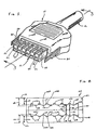
- a terminator generally indicated by reference character 10 in accordance with the present invention implemented in the form of a plug terminator for a multiple conductor cable 12.
- the cable 12 is shown in the Figures as being a round transmission cable it lies within the contemplation of the present invention that the plug terminator (10 or 10 ⁇ , Figures 10 and 11) as disclosed herein may be used with equal efficacy in conjunction with a flat cable (either ribbon cable or discrete wire cable).
- the cable 12 includes an outer jacket 14 ( Figure 3) of an insulating material surrounding a plurality of individual jacketed conductors 16. Each conductor 16 itself includes an insulating jacket 16J surrounding a wire conductor 16W.
- a conducting sheath 18 disposed under the outer jacket 14 of the cable 12 serves as a portion of the grounding and shielding structure of the cable 12. The sheath 18 is terminated by a metallic ferrule 20, such as that disclosed in US-A-4,416,501.
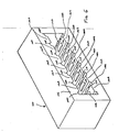
- the ground structure 22 includes a baseplate portion 24 having a main planar surface with an integral portion 28 projecting forwardly therefrom.
- the ground structure 22 is shown as being provided with an upper and a lower working surface 30A and 30B respectively thereon, it should be understood that a ground structure 22 having only one working surface 30 may be used and remain within the contemplation of the present invention.
- the terminator can be implemented with a ground structure that includes only the structure on the upper working surface 30A of the ground structure 2 (that is, the structure above the dividing plane 31 extending through the baseplate portion 24 of the ground structure 22). In such an instance the opposite surface of the ground structure 22 would preferably be planar.
- the remaining elements of the terminator as hereafter described would be appropriately modified to accept a ground structure 22 of this form.
- a plurality of walls 32 extends from the forward projecting portion of the respective upper and lower working surface 30A, 30B, respectively, of the baseplate 24.
- the walls 32 are arranged in side-by-side relationship to define a plurality of channels 34 across the surfaces of the projecting portion 28 of the baseplate 24.
- the axes of the adjacent channels 34 are parallel to each other, although it is understood that such a relationship is not mandated. It should also be understood that although each working surface 30A, 30B of the baseplate 24 is shown as having the same number of channels 34, such a situation is also not necessarily required.
- the planar portion 26 of the baseplate 24 behind the projecting portion 28 has flanges 38 which flare farther rearwardly and slightly outwardly from the baseplate 24.
- the flanges 38 carry posts 40.
- the posts 40 be electrically conductive and in electrical contact with the conductive material of the baseplate 14. It should be appreciated that a ground structure of more than two working surfaces may be defined by disposing additional baseplates 24 (whether each baseplate implemented with one or two working surfaces) in any convenient stacked relation.
- the ground structure 22 is shown as being fabricated as an integral metallic member, although it should be understood that any suitable construction for the ground structure 22 may be used.
- the ground structure 22 can be formed from plastic with its entire upper and lower working surfaces 30A, 30B (including the walls 32 on the projecting portions 28) lined with a suitable conductive material.
- the baseplate 24 may be formed or stamped from a sheet of conductive material with slots provided near the forward end thereof.
- the end walls 32 may be formed from similar slotted stampings. The baseplate 24 and the walls 32 are joined via the slots to define the ground structure 22 as shown in the Figures.
- the plug terminator 10 further comprises a contact support member 44 having a main body portion 46 with an array of trenches 48 formed therein.
- the contact support member 44 is formed of an insulating material.
- a partition 50 having an indentation 50G is provided near the forward end of the body portion 46 of the contact support member 44.
- An array of apertures 52 (visible on the lower member 44 in Figure 2) is provided through the body 46 of the support member 44 in the region behind the partition 50, with one of the apertures 52 being aligned with the mouth of each of the grooves 48 for a purpose to be described.
- An array of fingers 54 extends forwardly from the body 46.
- the fingers 54 correspond in number to the number of channels 34 provided on the ground structure 22. In the assembled condition the fingers 54 extend into the channels 34 so that the forward ends of the fingers 54 are coterminal with the forward edge of the ground structure 22.
- An array of electrical contacts elements 58 of any suitable configuration are embedded in the insulating material of the fingers 54.
- the contact elements 58 are arranged such that the planar blade of each contact element 58 is exposed on the surface of the finger 54 in which it is disposed.
- the contact element 58 extends rearwardly from the fingers 54 through the material of the partition 50.
- the contact element 58 ends in an overlying relationship with the apertures 52 in the body 46 just forwardly of the mouths of the trenches 48 therein. As seen in the Figures the top surfaces of the walls 32 of the ground structure 22 extend above the contact elements 58 when the same are received in the channels 34.
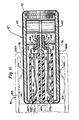
- the plug 14 includes a protective casing generally indicated by reference character 64.
- the casing 64 is defined by complementary shell members 66A, 66B.
- Each shell member 66A, 66B has a forward cutout 68 having a tongue 68T therein.
- the configuration of the cutout 68 corresponds to the configuration of the body portion 46 of the contact support member in the vicinity of the partition 50.
- the rear wall of each of the shell cons 66A, 66B has cooperating grooved openings 70 therein.
- the openings 70 are shaped to generally conform to the exterior configuration of and are sized to closely accept the transmission cable 12 in either round or flat form.
- the shells 66A, 66B Adjacent to the rear wall of the shells 66A, 66B is a pair of abutments 72 with recesses 74.
- the recesses 74 are configured to accept snugly the posts 40 on the ground structure 22 in a press fit relationship.
- the shells 66A, 66B are each fabricated of a conductive material. It should be understood that the shells may be fabricated from a plastic material in which case a conductive surface 76 is formed by a suitable conductor layer disposed on the inner surface of each of the shells 66A, 66B (as shown in Figure 3 for economy of illustration).
- the sidewalls of the shells 66A, 66B each carry notches 78 sized to accept locking tabs 80 which serve to hold the casing 64 together.
- the complementary shells 66A and 66B close on each other and are locked together by the tabs 80 and the press fit engagement of the posts 40 in the recesses 74 in the abutments 72.
- the tongue 68T near the cutout 68 adjacent the front of the casing 64 engages in the groove 50G.
- the multiple conductor cable 12 extends through the registered openings 70 in the rear of the shells 66A, 66B and into the volume defined in the rear of the casing 64.
- the external jacket 14 of the cable 12 is stripped a predetermined distance from its end to expose the individual jacketed conductors 16 therein.
- An insulation displacement contact 82 severs the exterior jacket 14 of the cable 12 and electrically interconnects with the ferrule 20 of the cable 12.
- the insulation displacement contact 82 is captured in the grooved openings 70 adjacent the rear aperture of the shell to thereby electrically interconnect the conductive surface 76 on the interior of the casing 64 to a predetermined electrical potential.
- the individual conductors 16 of the cable 12 Prior to the closing of the casing by the interengagement of the shells 66A, 66B, the individual conductors 16 of the cable 12 are themselves stripped of their jackets 16J and the conductive wires 16W thereof laid in one of the trenches 48 extending in the body portion 46 of the contact support structure 44. The end of each of the wires 16W overlays the end of one of the contact elements 58.
- the wires 16W and the contacts 58 may be suitably attached, as by welding, solder or insulation displacement contacts to interconnect the wires 16W to the contacts 58 and remain within the contemplation of the present invention.
- Figures 10 and 11 illustrate an alternative embodiment of the cable plug terminator form 10 ⁇ of the invention generally similar to the embodiment of the invention shown in Figures 1 to 3.
- the contact support member 44 is provided with a main body portion 46, formed of an insulating material, from which a plurality of fingers 54 extend.
- the fingers 54 each include a recess 55 having a lip 55L ( Figure 11) provided therein.
- Each finger 54 is, therefore, a substantially hollow member in which a spring electrical contact element 58 is received.
- the tail portion of the contact 58 is provided with a slot 58S that imparts to the tail portion of the contact 58 a configuration generally similar to that of an insulation displacement contact.
- the head or forward end of the contact 58 is captured by the lip 55L while the tail end of the contact 58 projects rearwardly from the main body portion 46 of the member 44.
- the generally linear portion 58L of the contact 58 between the curved electrical engaging region 58C and the slotted tail 58S is captured at each lateral horizontal edge of the contact 58 in a groove 59 formed in each of the sidewalls of the main portion of the support member 44.
- a portion of the contact 58 is cut away to clearly illustrate the groove 59.
- the member 44 is mounted to the ground structure 22 in a manner generally similar to the arrangement formed and shown in connection with Figures 2 and 3.
- the fingers 54 of the member 44 are each received in one of the channels 34 defined by the walls 32 of the ground structure 22.
- the member 44 is positioned on the structure 22 by the engagement of the main portion 46 of the member 44 with the inner ends of the walls 34 of the structure, as is illustrated in the Figure.
- the member 44 is held in the position shown in drawing Figure 11 by an abutment 26A formed on the planar portion 26 of the baseplate 24 of the structure 22.
- any suitable expedient may be used to position a member 44 on one (or both) surface(s) of the structure 22.
- the welding apertures 52 (perhaps best seen in Figure 2) provided in the planar portion 26 of the structure 22 are eliminated inasmuch as the welded attachment of the conductor wires 16W to the tail portion of the contact 58 may be effected by a facial welding process.
- the wires 16W of the conductors 16 are bent, as at 16B ( Figure 11), to cause the axis of the portion of the wire 16W immediately rearwardly to the facial end of the wire 16W to extend linearly through the tail end portion of the contact 58.
- the protective casing 64 of the connector 10 ⁇ is also slightly modified from that shown in Figures 2 and 3 in that the shell portions 66A, 66B extend forwardly and turn downwardly and upwardly, respectively, to define the tongue portion 68T such that the forward edge of the casing is coextensive with the forward face 44F of the contact support member 44.
- the shell members 66A and 66B are held together in the same manner as that described for the arrangement of the connector shown in Figures 2 and 3. That is, the posts 40 on the ground structure 22 are press-fit into recesses 74 in the abutments 72 in the shells 66A, 66B.
- the sidewalls of the shells 66A, 66B are notched, as at 78, to accept locking tabs 80.
- the casing 64 shown in Figures 10 and 11 may be fabricated entirely of a conductive material.
- the shells 66A, 66B can be fabricated of a nonconductive material, e.g., plastic, in which event conductive layers 76 should be provided on both the interior and exterior surfaces thereof.
- the layers 76 are illustrated in the Figures for economy of illustration.
- the header 81 includes an insulating housing 82 having an array of pins 83 extending therefrom. Each pin 83 is respectively received within one of the recesses 55 in the fingers 54. Each pin 83 is in electrical engagement with the electrical engaging region 58C of the contact 58.
- the housing 82 also contains spring contacts 84 which engage the metallic shells 66A, 66B (or the layer 76 disposed thereon in the event the shells 66A, 66B are formed of insulating material) thereby to establish a grounded interconnection with the shells 66A, 66B.
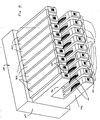
- a terminator 10 ⁇ in accordance with the present invention may be used in the environment of an edge card terminator for substrates such as a printed circuit board 86 having multiple conductive tracings 88 thereon.
- a ground structure 22 similar to that described in connection with Figure 1 through 3 or in connection with Figures 10 and 11 is disposed both above and below the board 86.
- the ground structures 22 are supported at their ends by a bracket 90.
- Each of the structures 22 receives a contact support member 44 ⁇ generally similar to that discussed in connection with Figures 1 through 3 or in connection with Figures 10 and 11 with the exception that the body portion 46 ⁇ thereof is truncated.
- the contact elements 58 emanating from the support member 46 ⁇ are directed joined to the conductive tracings 88 on the surfaces of the board 86. It should be appreciated that the terminator 10 ⁇ may be used to service only one of the surfaces of the board 86.
- the ground structure 22 is connectable to a predetermined electrical potential (e.g., chassis or logic ground). Since the walls 32 near the forward projecting portions 28 of the baseplate 24 extend above the signal carrying contacts 58 generally U-shaped receptacles are formed in which the signal carrying contacts 58 are disposed. The ground structure 22 thus electrically shields and isolates each signal carrying contact 58 from each adjacent signal carrying contact, whether these contacts are sidewise and/or vertically adjacent.
- a predetermined electrical potential e.g., chassis or logic ground.
- FIGS. 6 and 7 shown are perspective and sectional views of a housing assembly 100 adapted to accept a terminator 10 or 10 ⁇ or 10 ⁇ as described heretofore.
- the housing 100 includes a main body portion 102 fabricated of a suitable insulating material such as molded plastic.
- the body 102 has a main opening that receives the terminator 10 or 10 ⁇ or 10 ⁇ therewithin.
- the housing is generally similar to that described in US-A-4,601,527.
- the upper and lower edges of the housing 102 are provided with an alternating array of lands 106A, 106B and grooves 108A, 108B, respectively.
- the surfaces of the lands 106A, 106B and the troughs of the grooves 108A, 108B are provided with suitable electrical contacts 110A, 110B and 112A, 112B respectively.
- the contacts are retained in the housing 100 in the standard manner. It should be understood that although in Figure 6 through 9 preloaded cantilevered beam contacts are illustrated the housing 100 (or 100 ⁇ ) in accordance with the present invention can be implemented using any suitable alternate form of contact.
- the contacts 110 and 112 are supported in the body 102 of the housing 100 such that, as measured with respect to a predetermined datum, the contacts 110 disposed on the lands 106 extend for a distance from the datum different than the distance that the contacts 112 extend from the datum.
- the reference datum is selected as the plane 116 containing the upper surface of the housing 102.
- the contacts 110A on the lands 106A extend for a distance 118 from the datum 116 that is greater than the distance 120 that the contacts 112A in the grooves 108A extend from the datum 116.
- the reference datum is selected to be the plane 122 containing the lower surface of the housing 102 and the distances defined between the contacts 110A is indicated by the character 124 and the distance defined by the contacts 112B is indicated by the character 126.
- an equally useful datum may be defined by a bisecting plane 130 ( Figure 8) extending parallel to the arrays of contacts and midway therebetween.
- the contacts 110A, 110B on the lands 106A, 106B respectively are spaced a distance 134 from the datum 130 while the contacts 112A, 112B in the grooves 108A, 108B, respectively are spaced from the datum 130 by the distance 136.
- a terminator 10 or 10 ⁇ or 10 ⁇ may be received in the housing 100 such that the upper surfaces of the walls 32 on the ground structure 22 are brought into electrically conductive engagement with the contacts in the grooves 108, while the contacts 58 supported in the contact support 44 are brought into electrically conductive engagement with the contacts 110 on the lands 106.
- the location of the signal and the ground connections on essentially two levels of the housing 100 permits the density of the connector to be increased. Since the ground connection is provided by the walls of the structure 22, the width dimension of the walls could by physically less than the width dimension of the signal carrying contact blades. This situation permits an increase in signal density while maintaining transmission line characteristics. Moreover the staggering of the signal and ground interconnection points on two levels permits further compression of the structure leading to yet greater density.
- the structure of the housing shown in Figures 6 through 8 is modified slightly as shown in Figure 9.
- the lands 106 are separated by slots 140.
- contact plates 142 are provied that overlie a portion of the slots 140.
- the ground structure 22 is slightly modified in that the walls 32 are extended to a height sufficient to permit the upper surfaces of the walls 32 to contact against the contact plates 142. It should be understood that in this embodiment (as well as the embodiment shown in Figures 6 through 8) the plates 142 (and the ground contacts 112) are preferably connected in common.
Priority Applications (1)
| Application Number | Priority Date | Filing Date | Title |
|---|---|---|---|
| AT87310079T ATE101757T1 (de) | 1986-11-18 | 1987-11-16 | Anschluss fuer elektrische mehrfach-leiter. |
Applications Claiming Priority (4)
| Application Number | Priority Date | Filing Date | Title |
|---|---|---|---|
| US93292186A | 1986-11-18 | 1986-11-18 | |
| US932921 | 1986-11-18 | ||
| US9100287A | 1987-09-02 | 1987-09-02 | |
| US91002 | 1987-09-02 |
Publications (3)
| Publication Number | Publication Date |
|---|---|
| EP0268441A2 true EP0268441A2 (fr) | 1988-05-25 |
| EP0268441A3 EP0268441A3 (en) | 1989-07-26 |
| EP0268441B1 EP0268441B1 (fr) | 1994-02-16 |
Family
ID=26782890
Family Applications (1)
| Application Number | Title | Priority Date | Filing Date |
|---|---|---|---|
| EP87310079A Expired - Lifetime EP0268441B1 (fr) | 1986-11-18 | 1987-11-16 | Terminal pour plusieurs conducteurs électriques |
Country Status (6)
| Country | Link |
|---|---|
| EP (1) | EP0268441B1 (fr) |
| JP (1) | JP2737843B2 (fr) |
| KR (1) | KR910002264B1 (fr) |
| CA (1) | CA1289211C (fr) |
| DE (1) | DE3789089T2 (fr) |
| HK (1) | HK1000397A1 (fr) |
Cited By (21)
| Publication number | Priority date | Publication date | Assignee | Title |
|---|---|---|---|---|
| US5057028A (en) * | 1986-11-18 | 1991-10-15 | E. I. Du Pont De Nemours And Company | Receptacle having a nosepeice to receive cantilevered spring contacts |
| US5169324A (en) * | 1986-11-18 | 1992-12-08 | Lemke Timothy A | Plug terminator having a grounding member |
| EP0587303A2 (fr) * | 1992-09-08 | 1994-03-16 | The Whitaker Corporation | Connecteur blinde pour transmission de donnés |
| US5297970A (en) * | 1993-02-11 | 1994-03-29 | Porta Systems Corp. | Connector block and connector block assembly with offset contacts |
| EP0610088A2 (fr) * | 1993-02-05 | 1994-08-10 | Thomas & Betts Corporation | Connecteur pour transmission de donnés à performance améliorée |
| US5487682A (en) * | 1992-09-08 | 1996-01-30 | The Whitaker Corporation | Shielded data connector |
| EP0634817A3 (fr) * | 1993-07-14 | 1996-06-05 | Thomas & Betts Corp | Connecteur blindé compact pour transmission de données. |
| WO1997010628A1 (fr) * | 1995-09-15 | 1997-03-20 | The Whitaker Corporation | Connecteur electrique blinde |
| US5641308A (en) * | 1995-04-28 | 1997-06-24 | Molex Incorporated | Electrical connector |
| US5718599A (en) * | 1994-11-21 | 1998-02-17 | Molex Incorporated | Small pitch dual row leaf connector |
| US5797770A (en) * | 1996-08-21 | 1998-08-25 | The Whitaker Corporation | Shielded electrical connector |
| EP0932286A1 (fr) * | 1997-05-14 | 1999-07-28 | Sega Enterprises, Ltd. | Procede de transmission de donnees, et systeme de jeu construit selon ledit procede |
| NL1012364C2 (nl) * | 1999-06-16 | 2000-12-19 | Berg Electronics Mfg | Connector. |
| NL1012361C2 (nl) * | 1999-06-16 | 2000-12-19 | Berg Electronics Mfg | Connector and contact elements for the same. |
| NL1012345C2 (nl) * | 1999-06-16 | 2000-12-19 | Berg Electronics Mfg | Connector and method for manufacturing such a connector. |
| WO2000077887A1 (fr) * | 1999-06-16 | 2000-12-21 | Fci 's-Hertogenbosch B.V. | Connecteur, procede de fabrication d'un tel connecteur, et element de contact pour un connecteur |
| US6224423B1 (en) | 1998-01-15 | 2001-05-01 | The Siemon Company | Enhanced performance telecommunications connector |
| US6324603B1 (en) | 1997-05-16 | 2001-11-27 | Kabushiki Kaisha Sega Enterprises | Data transmission system and game system using the same |
| US6358091B1 (en) | 1998-01-15 | 2002-03-19 | The Siemon Company | Telecommunications connector having multi-pair modularity |
| US6780054B2 (en) | 1998-01-15 | 2004-08-24 | The Siemon Company | Shielded outlet having contact tails shield |
| US10008811B2 (en) | 2014-05-30 | 2018-06-26 | Molex, Llc | Electrical connector |
Families Citing this family (7)
| Publication number | Priority date | Publication date | Assignee | Title |
|---|---|---|---|---|
| DE19956106B4 (de) * | 1998-11-23 | 2011-02-03 | The Whitaker Corp., Wilmington | Elektrischer Steckverbinder bestehend aus einer Verbinderbuchse und einem Verbinderstecker, sowie Verbinderbuchse und Verbinderstecker |
| DE10000016B4 (de) * | 1999-01-04 | 2011-02-17 | The Whitaker Corp., Wilmington | Elektrischer Steckverbinder bestehend aus einer Verbinderbuchse und einem Verbinderstecker, sowie Verbinderbuchse und Verbinderstecker |
| US6857899B2 (en) | 1999-10-08 | 2005-02-22 | Tensolite Company | Cable structure with improved grounding termination in the connector |
| US6217372B1 (en) | 1999-10-08 | 2001-04-17 | Tensolite Company | Cable structure with improved grounding termination in the connector |
| US6428344B1 (en) | 2000-07-31 | 2002-08-06 | Tensolite Company | Cable structure with improved termination connector |
| JP4917784B2 (ja) * | 2005-09-26 | 2012-04-18 | 富士通コンポーネント株式会社 | コネクタ |
| JP6280001B2 (ja) * | 2014-08-22 | 2018-02-14 | ホシデン株式会社 | コネクタ |
Citations (5)
| Publication number | Priority date | Publication date | Assignee | Title |
|---|---|---|---|---|
| FR2334267A1 (fr) * | 1975-11-14 | 1977-07-01 | Du Pont | Dispositif de contact pour le raccordement d'un cable coaxial |
| EP0074205A1 (fr) * | 1981-08-24 | 1983-03-16 | W.L. Gore & Associates, Inc. | Connecteur pour un câble coaxial blindé |
| EP0080365A1 (fr) * | 1981-11-23 | 1983-06-01 | E.I. Du Pont De Nemours And Company | Raccordement d'un câble blindé |
| EP0094173A1 (fr) * | 1982-05-07 | 1983-11-16 | AMP INCORPORATED (a New Jersey corporation) | Connecteur électrique à élément commun de connexion |
| EP0189288A2 (fr) * | 1985-01-18 | 1986-07-30 | E.I. Du Pont De Nemours And Company | Connecteur blindé et assemblage |
Family Cites Families (5)
| Publication number | Priority date | Publication date | Assignee | Title |
|---|---|---|---|---|
| JPS522190U (fr) * | 1975-06-24 | 1977-01-08 | ||
| US4386819A (en) * | 1981-08-31 | 1983-06-07 | Amp Incorporated | RF Shielded assembly having capacitive coupling feature |
| US4420201A (en) * | 1981-11-09 | 1983-12-13 | Amp Incorporated | Shielding assembly enclosing an electrical connector terminating shielded cable |
| JPS5949173A (ja) * | 1982-09-10 | 1984-03-21 | 富士通株式会社 | コネクタ |
| JPS6128284U (ja) * | 1984-07-26 | 1986-02-20 | 本多通信工業株式会社 | フラツトケ−ブル用コネクタ |
-
1987
- 1987-11-12 CA CA000551742A patent/CA1289211C/fr not_active Expired - Lifetime
- 1987-11-16 EP EP87310079A patent/EP0268441B1/fr not_active Expired - Lifetime
- 1987-11-16 DE DE3789089T patent/DE3789089T2/de not_active Expired - Lifetime
- 1987-11-17 KR KR1019870012939A patent/KR910002264B1/ko not_active IP Right Cessation
- 1987-11-18 JP JP62291667A patent/JP2737843B2/ja not_active Expired - Lifetime
-
1997
- 1997-10-21 HK HK97101975A patent/HK1000397A1/xx not_active IP Right Cessation
Patent Citations (5)
| Publication number | Priority date | Publication date | Assignee | Title |
|---|---|---|---|---|
| FR2334267A1 (fr) * | 1975-11-14 | 1977-07-01 | Du Pont | Dispositif de contact pour le raccordement d'un cable coaxial |
| EP0074205A1 (fr) * | 1981-08-24 | 1983-03-16 | W.L. Gore & Associates, Inc. | Connecteur pour un câble coaxial blindé |
| EP0080365A1 (fr) * | 1981-11-23 | 1983-06-01 | E.I. Du Pont De Nemours And Company | Raccordement d'un câble blindé |
| EP0094173A1 (fr) * | 1982-05-07 | 1983-11-16 | AMP INCORPORATED (a New Jersey corporation) | Connecteur électrique à élément commun de connexion |
| EP0189288A2 (fr) * | 1985-01-18 | 1986-07-30 | E.I. Du Pont De Nemours And Company | Connecteur blindé et assemblage |
Cited By (32)
| Publication number | Priority date | Publication date | Assignee | Title |
|---|---|---|---|---|
| USRE35508E (en) * | 1986-11-18 | 1997-05-13 | Berg Technology, Inc. | Plug terminator having a grounding member |
| US5169324A (en) * | 1986-11-18 | 1992-12-08 | Lemke Timothy A | Plug terminator having a grounding member |
| US5057028A (en) * | 1986-11-18 | 1991-10-15 | E. I. Du Pont De Nemours And Company | Receptacle having a nosepeice to receive cantilevered spring contacts |
| WO1992009119A1 (fr) * | 1990-11-07 | 1992-05-29 | E.I. Du Pont De Nemours And Company | Adaptateur de fiche possedant un element saillant de mise a la terre, et prise de courant correspondante comportant une partie avant pour recevoir des contacts elastiques en porte a faux |
| EP0587303A3 (en) * | 1992-09-08 | 1995-08-23 | Whitaker Corp | Shielded data connector |
| EP0865113A3 (fr) * | 1992-09-08 | 1998-12-23 | The Whitaker Corporation | Connecteur blindé pour transmissions de données |
| US5487682A (en) * | 1992-09-08 | 1996-01-30 | The Whitaker Corporation | Shielded data connector |
| EP0865113A2 (fr) * | 1992-09-08 | 1998-09-16 | The Whitaker Corporation | Connecteur blindé pour transmissions de données |
| US5584727A (en) * | 1992-09-08 | 1996-12-17 | The Whitaker Corporation | Shielded data connector |
| US5586911A (en) * | 1992-09-08 | 1996-12-24 | The Whitaker Corporation | Shielding data connector |
| EP0587303A2 (fr) * | 1992-09-08 | 1994-03-16 | The Whitaker Corporation | Connecteur blinde pour transmission de donnés |
| EP0610088A2 (fr) * | 1993-02-05 | 1994-08-10 | Thomas & Betts Corporation | Connecteur pour transmission de donnés à performance améliorée |
| EP0610088A3 (fr) * | 1993-02-05 | 1996-02-07 | Thomas & Betts Corp | Connecteur pour transmission de donnés à performance améliorée. |
| US5297970A (en) * | 1993-02-11 | 1994-03-29 | Porta Systems Corp. | Connector block and connector block assembly with offset contacts |
| EP0634817A3 (fr) * | 1993-07-14 | 1996-06-05 | Thomas & Betts Corp | Connecteur blindé compact pour transmission de données. |
| US5718599A (en) * | 1994-11-21 | 1998-02-17 | Molex Incorporated | Small pitch dual row leaf connector |
| US5641308A (en) * | 1995-04-28 | 1997-06-24 | Molex Incorporated | Electrical connector |
| WO1997010628A1 (fr) * | 1995-09-15 | 1997-03-20 | The Whitaker Corporation | Connecteur electrique blinde |
| US5797770A (en) * | 1996-08-21 | 1998-08-25 | The Whitaker Corporation | Shielded electrical connector |
| EP0932286A4 (fr) * | 1997-05-14 | 2001-02-07 | Sega Enterprises Kk | Procede de transmission de donnees, et systeme de jeu construit selon ledit procede |
| EP0932286A1 (fr) * | 1997-05-14 | 1999-07-28 | Sega Enterprises, Ltd. | Procede de transmission de donnees, et systeme de jeu construit selon ledit procede |
| US6324603B1 (en) | 1997-05-16 | 2001-11-27 | Kabushiki Kaisha Sega Enterprises | Data transmission system and game system using the same |
| US6358091B1 (en) | 1998-01-15 | 2002-03-19 | The Siemon Company | Telecommunications connector having multi-pair modularity |
| US6224423B1 (en) | 1998-01-15 | 2001-05-01 | The Siemon Company | Enhanced performance telecommunications connector |
| US6328601B1 (en) | 1998-01-15 | 2001-12-11 | The Siemon Company | Enhanced performance telecommunications connector |
| US6629858B2 (en) | 1998-01-15 | 2003-10-07 | The Siemon Company | Enhanced performance telecommunications connector |
| US6780054B2 (en) | 1998-01-15 | 2004-08-24 | The Siemon Company | Shielded outlet having contact tails shield |
| WO2000077887A1 (fr) * | 1999-06-16 | 2000-12-21 | Fci 's-Hertogenbosch B.V. | Connecteur, procede de fabrication d'un tel connecteur, et element de contact pour un connecteur |
| NL1012345C2 (nl) * | 1999-06-16 | 2000-12-19 | Berg Electronics Mfg | Connector and method for manufacturing such a connector. |
| NL1012361C2 (nl) * | 1999-06-16 | 2000-12-19 | Berg Electronics Mfg | Connector and contact elements for the same. |
| NL1012364C2 (nl) * | 1999-06-16 | 2000-12-19 | Berg Electronics Mfg | Connector. |
| US10008811B2 (en) | 2014-05-30 | 2018-06-26 | Molex, Llc | Electrical connector |
Also Published As
| Publication number | Publication date |
|---|---|
| KR890005927A (ko) | 1989-05-17 |
| HK1000397A1 (en) | 1998-03-13 |
| JP2737843B2 (ja) | 1998-04-08 |
| CA1289211C (fr) | 1991-09-17 |
| DE3789089D1 (de) | 1994-03-24 |
| DE3789089T2 (de) | 1994-07-14 |
| EP0268441A3 (en) | 1989-07-26 |
| KR910002264B1 (ko) | 1991-04-08 |
| EP0268441B1 (fr) | 1994-02-16 |
| JPS63158766A (ja) | 1988-07-01 |
Similar Documents
| Publication | Publication Date | Title |
|---|---|---|
| EP0268441B1 (fr) | Terminal pour plusieurs conducteurs électriques | |
| US4824383A (en) | Terminator and corresponding receptacle for multiple electrical conductors | |
| EP0368982B1 (fr) | Systeme de connecteur pour conducteurs electriques multiples | |
| EP0735612B1 (fr) | Connecteur électrique avec support de conducteurs et blindage amélioré | |
| EP0590667B1 (fr) | Connecteur pour câbles de haute densité | |
| EP0263654B1 (fr) | Fiche électrique et assemblage d'un réceptacle de connecteur | |
| US4457575A (en) | Electrical connector having improved shielding and keying systems | |
| JP3410501B2 (ja) | シールド型コネクタ | |
| EP0634817B1 (fr) | Connecteur blindé compact pour transmission de données | |
| JP2911860B2 (ja) | 低プロフィールコネクタシステム | |
| US6582255B2 (en) | High-density plug connector for twisted pair cable | |
| US6210230B1 (en) | Cable connector | |
| WO2002061892A1 (fr) | Interface de connecteur et systeme de retenue destines a un connecteur haute densite | |
| US5297970A (en) | Connector block and connector block assembly with offset contacts | |
| EP0614248B1 (fr) | Interface pour un réseau local (LAN) | |
| US4537459A (en) | Jack for EMI/RFI shield terminating modular plug connector | |
| US5509824A (en) | Enhanced performance data connector | |
| EP0231539A1 (fr) | Assemblage de connecteurs électriques blindés et codés | |
| EP0634816B1 (fr) | Alignement vertical de composants de connecteur électrique blindé | |
| EP0323114A1 (fr) | Assemblage pour la distribution de donées | |
| US6012943A (en) | Insulation displacement connector | |
| EP0641043A2 (fr) | Connecteur compact, et blindé pour transmission de données | |
| AU607444B2 (en) | Terminator for multiple electrical conductors | |
| KR100558821B1 (ko) | 모듈라커넥터 |
Legal Events
| Date | Code | Title | Description |
|---|---|---|---|
| PUAI | Public reference made under article 153(3) epc to a published international application that has entered the european phase |
Free format text: ORIGINAL CODE: 0009012 |
|
| AK | Designated contracting states |
Kind code of ref document: A2 Designated state(s): AT BE CH DE FR GB IT LI LU NL SE |
|
| PUAL | Search report despatched |
Free format text: ORIGINAL CODE: 0009013 |
|
| AK | Designated contracting states |
Kind code of ref document: A3 Designated state(s): AT BE CH DE FR GB IT LI LU NL SE |
|
| 17P | Request for examination filed |
Effective date: 19900115 |
|
| 17Q | First examination report despatched |
Effective date: 19920323 |
|
| GRAA | (expected) grant |
Free format text: ORIGINAL CODE: 0009210 |
|
| AK | Designated contracting states |
Kind code of ref document: B1 Designated state(s): AT BE CH DE FR GB IT LI LU NL SE |
|
| PG25 | Lapsed in a contracting state [announced via postgrant information from national office to epo] |
Ref country code: IT Free format text: LAPSE BECAUSE OF FAILURE TO SUBMIT A TRANSLATION OF THE DESCRIPTION OR TO PAY THE FEE WITHIN THE PRE;WARNING: LAPSES OF ITALIAN PATENTS WITH EFFECTIVE DATE BEFORE 2007 MAY HAVE OCCURRED AT ANY TIME BEFORE 2007. THE CORRECT EFFECTIVE DATE MAY BE DIFFERENT FROM THE ONE RECORDED.SCRIBED TIME-LIMIT Effective date: 19940216 Ref country code: BE Effective date: 19940216 Ref country code: SE Effective date: 19940216 Ref country code: NL Effective date: 19940216 Ref country code: LI Effective date: 19940216 Ref country code: AT Effective date: 19940216 Ref country code: CH Effective date: 19940216 |
|
| REF | Corresponds to: |
Ref document number: 101757 Country of ref document: AT Date of ref document: 19940315 Kind code of ref document: T |
|
| REF | Corresponds to: |
Ref document number: 3789089 Country of ref document: DE Date of ref document: 19940324 |
|
| ET | Fr: translation filed | ||
| REG | Reference to a national code |
Ref country code: CH Ref legal event code: PL |
|
| NLV1 | Nl: lapsed or annulled due to failure to fulfill the requirements of art. 29p and 29m of the patents act | ||
| PG25 | Lapsed in a contracting state [announced via postgrant information from national office to epo] |
Ref country code: LU Free format text: LAPSE BECAUSE OF NON-PAYMENT OF DUE FEES Effective date: 19941130 |
|
| PLBE | No opposition filed within time limit |
Free format text: ORIGINAL CODE: 0009261 |
|
| STAA | Information on the status of an ep patent application or granted ep patent |
Free format text: STATUS: NO OPPOSITION FILED WITHIN TIME LIMIT |
|
| 26N | No opposition filed | ||
| REG | Reference to a national code |
Ref country code: GB Ref legal event code: 732E |
|
| REG | Reference to a national code |
Ref country code: FR Ref legal event code: TP |
|
| REG | Reference to a national code |
Ref country code: GB Ref legal event code: 732E |
|
| REG | Reference to a national code |
Ref country code: GB Ref legal event code: IF02 |
|
| PGFP | Annual fee paid to national office [announced via postgrant information from national office to epo] |
Ref country code: GB Payment date: 20021002 Year of fee payment: 16 |
|
| PGFP | Annual fee paid to national office [announced via postgrant information from national office to epo] |
Ref country code: FR Payment date: 20021105 Year of fee payment: 16 |
|
| PG25 | Lapsed in a contracting state [announced via postgrant information from national office to epo] |
Ref country code: GB Free format text: LAPSE BECAUSE OF NON-PAYMENT OF DUE FEES Effective date: 20031116 |
|
| GBPC | Gb: european patent ceased through non-payment of renewal fee |
Effective date: 20031116 |
|
| PG25 | Lapsed in a contracting state [announced via postgrant information from national office to epo] |
Ref country code: FR Free format text: LAPSE BECAUSE OF NON-PAYMENT OF DUE FEES Effective date: 20040730 |
|
| REG | Reference to a national code |
Ref country code: FR Ref legal event code: ST |
|
| PGFP | Annual fee paid to national office [announced via postgrant information from national office to epo] |
Ref country code: DE Payment date: 20061130 Year of fee payment: 20 |